Building Knowledge Bases for the Generation of
Software Documentation
††thanks: This work is partially
supported by the Engineering and Physical Sciences Research Council
(epsrc) Grant J19221, by bc/daad arc Project 293,
and by the Commission of the European Union Grant lre-62009.
Abstract
Automated text generation requires a underlying knowledge base from which to generate, which is often difficult to produce. Software documentation is one domain in which parts of this knowledge base may be derived automatically. In this paper, we describe drafter, an authoring support tool for generating user-centred software documentation, and in particular, we describe how parts of its required knowledge base can be obtained automatically.
1 Introduction
Automated text generation is becoming an attractive technology because it allows for the generation of text in different styles and in different languages from a single underlying knowledge base. The well-known problem with the technology is that this knowledge base is often difficult to build. In most research generation systems, this knowledge base is essentially built by hand. No general solution to this problem has been proposed because each application has its own domain specific requirements.
It is clear, however, that for text generation technology to become viable, there must be some way to obtain at least portions of the knowledge base automatically. There could be a program which automatically derives the knowledge base or perhaps the knowledge base could be built as part of manual processes that would have to be performed anyway. Either way, the marginal cost of adding text generation would be greatly reduced.
In this paper, we show that software documentation is an attractive application for multilingual text generation because it is an area in which pre-built knowledge bases are becoming available. This is due in large part to the advancements in the user interface design community which we will review first. We then discuss the nature of the knowledge base required for the generation of documentation and how parts of it might be derived automatically. Finally, we illustrate this idea using drafter, a support tool for generating multilingual software documentation.
2 Background
Researchers in user interface design have started to build tools which produce both code and documentation. These tools tend to be based on a central model of the interface under development, the interface model, a formal representation which can be used not only for code generation but also for document generation, e.g., [\citenamePuerta and Szekely1994, \citenameMoriyon et al.1994]. Moriyon et al \shortcitemoriyon94:hci, for example, have used the interface model in the generation of on-line help. Their help messages indicate the actions a user can perform in a particular situation and what would result from these actions. They report, however, that task-oriented help is beyond the capabilities of their system; task-oriented help would indicate why the user might want to perform any of the actions that are available.
In general, however, the documentation produced by these systems is limited in two main ways: it does not correspond to task-oriented documentation, which is, however, what end-users require and it is usually based on simple template generation, which does not allow flexibility with regard to the style of the text produced or the language that is used. These limitations stem, on the one hand, from the fact that interface models in general contain system-oriented information (e.g., what happens when a button is pushed) but not task-oriented information (e.g., why one might want to push the button), and, on the other hand, from the focus of the research, that is system and interface design and not natural language generation.
In the drafter project, we have attempted to address these two issues. We address the first by providing tools that allow technical authors to build richer interface models. These richer models integrate task information into the information already available in interface models. This task information, which is commonly found in task models, e.g., GOMS [\citenameCard et al.1983], supports the production of user-centred documentation. We address the second by providing more general text generation facilities which support multiple styles and multiple languages.
3 Representing the users’ tasks
Early in the drafter project, we conducted interviews with technical authors (mostly software documentation specialists) in order to understand the documentation process as it currently exists, to see if an authoring tool would be helpful, and if so how it might be used. We found that technical authors start the documentation process by learning how to use the interface in question, constructing a user-oriented mental model of the product. They frequently have no input other than the software itself. The authors indicated that they would welcome tools to help them collect the appropriate information and create a formal representation of the resulting model. Such a representation would support iterative construction of the documentation and information reuse.
Building our drafting tool, therefore, required us first to determine how to represent the model of a task, and then to build tools for creating and manipulating this model. Given that the general structure of instructional texts is hierarchical, we chose a representation that expresses a hierarchy of goals and sub-goals. The representation is thus similar to the traditional structures found in AI planning, e.g., [\citenameSacerdoti1977], and also to task models used in interface design, e.g., [\citenameCard et al.1983]. Because user documentation frequently includes information other than the raw actions to be performed, our representation allows authors to include information not typically found in traditional plan representations such as: user-oriented motivational goals, helpful side-effects, and general comments.
As an example, consider the representation of a sub-set of the procedure for saving a new file in a Microsoft Word-like editor shown in Figure 1. The oval boxes in the figure represent actions and the rectangles represent plans. Each of the action nodes in this structure represent interconnected complexes of procedural and descriptive instances. For example, the main user goal of saving a document, represented in the figure by the action node “Save a Document”, is implemented in the knowledge base as a complex of instances representing the action being performed (in this case saving), the agent who performs action (the reader), the patient on whom the action is performed (the current document), etc. All of this information is required to generate expressions of the action, but presenting it would overly complicate the graph.

The links actually shown in the figure are based on the procedural relations in the domain model. For example, the plan for saving a document (Save-Document-Plan) is linked to its goal (Save A Document), to its precondition (Open-Save-As), and to its sub-actions of typing a name for the current document (Type-Document-Name), opening the folder in which it is to be saved (Open-Folder), and clicking the Save button (Choose-Save-Button). The precondition (Open-Save-As) must be performed before the sub-steps may be attempted and is in turn linked to further sub-plans (Choosing-Plan and Clicking-Plan). This indicates that the Save-As dialog box may be opened by either choosing the Save option from the file menu (Choose-Save-Option) or clicking the Save button on the tool bar (Click-Save-Icon).
This task model represents the procedures that a user might perform when using an application and is the basis for generating user-centred documentation, such as one of drafter’s texts shown in Figure 4. It includes the users’ high-level goals (e.g., “save a document”) as well as their low-level interface manipulations (“choose the save button”).
4 Input from the Design Process
In our earlier work, we provided tools that supported the construction of the task model by hand [\citenameParis et al.1995]. This went some way to addressing the technical authors’ desire for a formal model and tools to build it. Building the model from scratch, however, even with the help of our menu based interface, was a tedious and lengthy process which could potentially have rendered the drafter system impractical. There was a clear need for facilities to ease the input task. In line with this, we noticed that certain elements of the model were also present in the specifications developed in user interface design environments. Indeed, we found that a number of the actions and objects in the model could be automatically acquired from a design tool, thus providing basic building blocks from which the full model could be constructed.
To illustrate this idea, we have built our example document editor application in VisualWorks, a widely available interface design environment [\citenameVis1994]. This tool allows one to define the windows, dialog boxes, and other widgets relevant for the application under development, and produces a prototype of the interface thus specified. Its output also includes declarative specifications of all the widgets. These specifications are thus available to be exploited by other systems. In particular, we found that these specifications could be readily transformed into a form appropriate for the knowledge base required by a text generation system such as drafter. In our example then, we build a VisualWorks mock-up of our word processing application, and drafter derives task model instances for all the windows and widgets in the application (e.g., the Save-As dialog box and all its widgets) directly from the SmallTalk source code. drafter is also able to infer the basic interface actions that can be performed on the various interface widgets and creates task model instances for them as well. For example, the system automatically defines a clicking action instance for any “button” on the interface. Similarly, it creates opening and closing actions for all “windows”.
Although this set of instances does not represent all the information that could, in principle, be derived from the SmallTalk specifications of the editor application, it nevertheless simplifies greatly the technical author’s task of knowledge specification by providing the building blocks from which higher-level procedures can be defined. In the case of our admittedly simple example, seven of the nine actions in the procedural structure are automatically specified. The author is required to specify only the main user goal action and the three plan nodes. This is, therefore, a step towards automatically building the knowledge base required for the generation system. It is also a step towards integrating the design and documentation processes, which is now widely recognised as being desirable. In our current work, we are investigating how more of the design knowledge can be made accessible and understandable to the technical authors, and what other tools would further facilitate the authors’ task. We are also looking at a tighter integration of the design and documentation processes, one in which the individuals involved work together during design.
5 DRAFTER
We now describe drafter, a technical authoring tool which supports the construction of the task model discussed above and the drafting of multilingual instructions from that model. We will focus on how it supports the author in augmenting the information automatically acquired from the interface design tool. drafter’s general architecture, shown in Figure 2, is based on two main processing modules:

-
The Author Interface (shown on the far left of the diagram) allows authors to build a task model and to control the drafting process.
-
The Drafting Tool (shown on the far right of the diagram) comprises two major components: the Text Planner and the Tactical Generator. The Text Planner determines the content and structure of the text as well as the detailed structure of the sentences therein. The Tactical Generator performs the surface realisation of the sentences.
The knowledge base (in the middle of the figure) underlies the task model built by the technical author. The Drafting Tool takes this representation as input and produces English and French drafts of the appropriate tutorial instructions. In this section we detail each of these components in the context of an example.
5.1 The Knowledge Base
The knowledge base supports the construction of the task model discussed above. It is an hierarchical structure implemented in loom [\citenameMacGregor1988]. The root is the Penman Merged Upper Model [\citenameBateman1995], an ontology of distinctions relevant in expressing actions, objects, and qualities in natural language. The knowledge base contains further layers corresponding to: (1) the concepts and relations general to all instructions; (2) those general only to software interfaces; and (3) those specific to the chosen software application domains (in our case text processing tools).
Using the drafter interface, technical authors specify hierarchical task models, such as the one shown in Figure 1, by building nodes and connecting them with the appropriate procedural relations. The low-level building blocks of the task model are derived automatically, and drafter allows the technical author to connect them and add higher-level task information as appropriate, using an interface based on controlled language and the use of menus to guide the author.
5.2 The Interface
drafter’s interface is implemented in clim and includes the following modules:
-
The Knowledge Editor allows the author to construct and maintain the procedural representation;
-
The Knowledge Grapher allows the author to visualise the hierarchical structure of the procedural representation;
-
The Draft Text Viewer allows the author to view and edit the automatically generated English and French drafts.
These functions can be invoked from menus or from mouse-sensitive objects in a style common to systems such as Motif.
5.2.1 The Knowledge Editor
This tool makes the structure of the knowledge base on which the task model is built more accessible to the author. It allows the author to perform two basic tasks: (1) specifying the action nodes appearing in the structure and not yet derived from the interface designed tool; and (2) linking existing nodes together with the appropriate plan instances and relations. The first of these tasks is performed using a controlled natural language interface while the second is done with a dialog box mechanism.
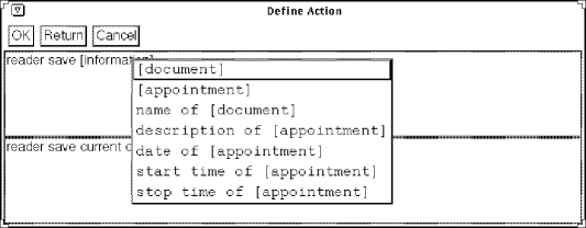
Specifying the nodes appearing in the task model involves specifying a full complex of linguistic entities and role-fillers (e.g., actors, actees, destinations). Because this structure may include many instances interconnected in potentially un-intuitive ways, we have provided a Controlled Natural Language (CNL) interface for the author. The interface is shown in Figure 3. This interface allows the author to work in terms of sentences rather than in terms of interconnected graphs. The figure, for example, shows the author in the process of specifying the node Save A Document. The top line of text (reader save [information]) shows the current state of the CNL specification. Words in brackets must be further specified. This is done by clicking on the word and selecting the appropriate pattern from a list of possible expansions. In the figure, the author has clicked on [information] and is presented with a list of the types of information from which [document] can be selected. This process is driven by a controlled natural language grammar which specifies possible expansions at each point of the derivation. The bottom line of text presents a fully expanded default at each point in the derivation. In the figure, this CNL text is “reader save current document” which could be expressed in English in a number of ways including “Save the current document” and “To save the document”.
Once the action nodes of the graph have been created, or perhaps while they are being created, the author has the ability to link them together using a set of predefined procedural relations: goal, precondition, sub-action, side-effect, warning, and cancellation. This is done with a graphical outlining mechanism. This mechanism allows authors to drag actions from the ACTIONS pane and drop them on the various procedural relation slots in the workspace pane, or, alternatively, to create new actions to fill the slots. The result is a procedural hierarchy such as the one shown in Figure 1.
This interface allows the author to specify the procedure in several ways. They may start from the main goal and work down the structure, or they may start by specifying all the low-level actions and object and work up the structure.
5.2.2 The Knowledge Grapher
The Knowledge Grapher prevents the author from losing orientation by maintaining the current state of the procedural structure in graphical form. This form is like that shown in Figure 1. Because the nodes are mouse-sensitive, it allows the author to initiate construction and maintenance functions by clicking on the appropriate nodes in the graph. Authors can also invoke the drafting tool from the graph.
5.2.3 The Draft Text Viewer
The author may draft multilingual instructions on any portion of the procedural structure at any point in the specification process. This task is performed by the Drafting Tool which is briefly described in the next section. This tool produces a draft of the instructions in English and French. These are presented to the author by the Draft Text Viewer. The presented text is mouse-sensitive, allowing the author to access the knowledge base entry for selected part of the text. In this way, the author can modify the underlying knowledge base while working from the text. In some cases the writer will decide to modify the generated text rather than the underlying knowledge. For this purpose, a text editor is currently provided.
5.3 The Drafting Tool
When the author initiates the Drafting Tool (see Figure 2), drafter calls the Text Planner with the discourse goal: make the user competent to perform the action specified by the author. The Text Planner selects the content appropriate for the instructions and builds a deep representation of the text to be generated. This portion of the text planning task is done by the text planner developed by Moore and Paris \shortcitemoore-paris-cl93. The Text Planner then specifies the detailed elements of the sentence structure. This portion of the task is done by a descendent of imagene [\citenameVander Linden and Martin1995].
Once complete, the text plans are passed to the Tactical Generator which generates the actual text in English and French. This task is performed by the English and French resources of the Komet-Penman Multi-Lingual development environment (KPML) [\citenameBateman1995], The drafts generated for the example procedure are shown in Figure 4.
To Save a Document
1. Choose Save from the file menu.
-OR-
Click on the Save icon.
Word displays the Save As dialog box.
2. Type the document name in the Save Current Document As field.
3. Open the folder of the document.
4. Choose the Save button.
You can quit the Save As dialog box by choosing the Cancel button.
Enregistrement d’un document
1. Choisir Enregistrer dans le menu Fichier.
OU BIEN
Cliquer sur l’icone Enregistrer.
Word affichera la zone de dialogue Enregistrer Sous.
2. Introduire le titre du document dans la zone de texte Enregistrer le Document.
3. Ouvrir le fichier du document.
4. Choisir le bouton Enregistrer.
Vous pouvez quitter la zone de dialogue Enregistrer Sous en choisissant le bouton Annuler.
In these texts, we see that the main user goal, that of saving a document, is given as a title to the series of steps. Then, the steps to be performed to achieve this goal are given. More detail on the drafting process can be found elsewhere.
6 Summary
In this paper, we have shown that the knowledge base required to produce user-oriented documentation automatically can be partially obtained from user interface tools and then augmented appropriately by technical authors. We presented a multilingual drafting tool which exploits output from an interface design tool and provides flexible support to technical authors for augmenting the interface model thus obtained in order to build the task model required to generate documentation. We argued that software documentation is thus an attractive and realistic application for natural language generation. In our current work, we are extending the percentage of the model that can be built automatically, so as to increase the usefulness of the system and its potential marketability. We are also planning to evaluate the system with technical authors.
References
- [\citenameBateman1995] John A. Bateman. 1995. KPML: The komet-Penman (Multilingual) Development Environment. Technical report, Institut für Integrierte Publikations- und Informationssysteme (IPSI), GMD, Darmstadt, July. Release 0.8.
- [\citenameCard et al.1983] S. K. Card, T. P. Moran, and A. Newell. 1983. The Psychology of Human-Computer Interaction. Lawrence Earlbaum Associates, Hillsdale, NJ.
- [\citenameMacGregor1988] Robert MacGregor. 1988. A Deductive Pattern Matcher. In Proceedings of the 1988 Conference on Artificial Intelligence, St Paul, MN, August. American Association of Artificial Intelligence.
- [\citenameMoore and Paris1993] Johanna D. Moore and Cécile L. Paris. 1993. Planning text for advisory dialogues: Capturing intentional and rhetorical information. Computational Linguistics, 19(4):651–694.
- [\citenameMoriyon et al.1994] Roberto Moriyon, Pedro Szekely, and Robert Neches. 1994. Automatic generation of help from interface design models. In CHI’94 Proceedings, Boston, Mass. Computer Human Interactions.
- [\citenameParis et al.1995] Cécile Paris, Keith Vander Linden, Markus Fischer, Anthony Hartley, Lyn Pemberton, Richard Power, and Donia Scott. 1995. A support tool for writing multilingual instructions. In IJCAI-95, pages 1398–1404.
- [\citenamePuerta and Szekely1994] Angel R. Puerta and Pedro Szekely. 1994. Model-based interface development. CHI-94 Tutorial Notes.
- [\citenameSacerdoti1977] Earl D. Sacerdoti. 1977. A Structure for Plans and Behavior. Elsevier, New York.
- [\citenameVander Linden and Martin1995] Keith Vander Linden and James H. Martin. 1995. Expressing local rhetorical relations in instructional text: A case-study of the purpose relation. Computational Linguistics, 21(1):29–57, March.
- [\citenameVis1994] ParcPlace Systems, Inc., 999 E. Arques Avenue, Sunnyvale, CA 94086-4593, 1994. The VisualWorks Documentation.