[
Communication with Chaos over Band-Limited Channels
Abstract
Methods of communications using chaotic signals use an ability of a chaos generator (encoder) and matched response system (decoder) to behave identically despite the instability of chaotic oscillations. Chaotic oscillations cover a wide spectral domain and can efficiently mask an information signal scrambled by the chaotic encoder. At the same time the wide spectrum poses intrinsic difficulties in the chaotic decoding if the chaotic signal is transmitted over real communication channels with limited bandwidth. We address this problem both numerically and experimentally. Two alternative ways to improve communication with chaos over band-limited channels are investigated. The first method employs a matching filter in the decoder which compensates channel distortions of the transmitted signal. This modification does not change the individual dynamics of chaotic systems in the synchronous state however the information signal injected into the driving system, breaks the symmetry between encoder and decoder and therefore exact recovery is impossible. We show that this approach has limited ability for synchronization of chaotic encoder. The second approach does not use adaptive compensation but relies on the design of chaotic oscillators which produce narrow-band chaotic waveforms.
pacs:
PACS numbers: 05.45.+b, 47.52.+j, 42.79.Sz]
I Introduction
Nonlinear oscillators with chaotic dynamics are able to generate broadband non-periodic signals. Due to local instability of chaotic trajectories it is practically impossible to reproduce exact waveforms of the signals generated by a chaotic oscillator. However, it has been shown [1, 2, 3, 4, 5, 6, 7, 8] that two systems with perfectly matched parameters can exhibit stable regime of identical chaotic oscillations if adequately coupled. This property makes chaotic systems attractive for applications in private communications as an analog message can be hidden within a complicated structure of a chaotic waveform and still be reconstructed at the receiver using another nonlinear system whose parameters are closely matched to ones of the first system.***We do not address here an issue of digital data transmission based on chaotic dynamics. Digital chaotic systems are essentially equivalent to stream cyphers known in cryptography[9]
Numerous algorithms of chaotic encoders and decoders based on the stability of regimes of identical chaotic oscillations were suggested in the past several years. In most of these algorithms, the information signal is added to the chaotic output generated by a chaotic encoder whose oscillations do not depend on . The mixture is transmitted to the decoder where it is used as a driving signal for the matched response system. Various implementations of the matched response systems were proposed, see for example [10, 11, 12, 13, 14, 15] and references therein. The common shortcoming of such methods of communication is that the driving signal which is “distorted” by the message , does not perfectly fit the decoder. As a result, recovered message will always contain some traces of chaotic waveforms no matter how perfectly the parameters of the decoder match those of the encoder. The amplitude of the chaotic contamination is small only if is small as compared to the chaotic signal . Unfortunately, this makes the whole system susceptible to noise.
A different approach to the problem of chaotic encoding and decoding was suggested in a number of papers [16, 17, 18, 19, 20, 21, 22]. The main idea of this approach is that information signal is injected into the feedback loop of the chaotic encoder. As a result the distorted chaotic signal returns back to the generator and influences the dynamics of the encoder. Now when the signal is applied to the decoder, it generates oscillations of the response system which are identical to the oscillations in the encoding generator. The message can be recovered using the open feedback loop of the response system. In this case (in the absence of noise), after initial transients, the information can be restored exactly. To be more specific consider the chaotic encoder of the form
| (1) | |||||
| (2) | |||||
| (3) |
where the scalar and the vector are the dynamical variables of the chaotic generator, is the information signal and is the output of the encoder. It is assumed that the choice of the vector function provides the chaotic behavior of the system (3). The dynamics of the decoder is described by the similar equations
| (4) | |||||
| (5) | |||||
| (6) |
where is the external signal driving the decoder. Evidently, if , solution satisfies (6). Stability of this regime of identical chaotic oscillations in systems (3) and (6) can be assured by the proper choice of the vector function . Then starting from arbitrary initial conditions, as , and therefore, . The mathematical background for stability of regimes of identical chaotic oscillations can be found elsewhere [24]. We would like to note that the described method of encoding and decoding is conceptually equivalent to a well known method of data encryption by means of digital data scramblers, see [23] and references therein.
The fact that the chaotic signal is broadband, poses serious problems if it is to be transmitted through a band-limited channel. Due to the nonlinear nature of the matched response system, if some part of the spectral components of the chaotic driving signal is not transmitted, or distorted, it affects the whole spectral domain of the signals produced in the response system. Even simple variations of channel gain or pure phase distortions in the channel (so called all-pass filters) may spoil drastically the response behavior[29].
Several recent papers [25, 26, 27, 28, 29] addressed this problem by attempting to eliminate the distortion imposed by the channel either using an inverse filter[25, 29] or augmenting the distorted signal by the signal of the second system passed through a complimentary band-stop filter[26]. For a mild first-order filter simulating the channel distortion, synchronized chaotic oscillations were achieved, however with less degree of stability as compared with the no-filter case. Both of these methods assume that the channel impulse response function is known at the receiver. In practice, however, channel characteristics are often unknown a priori and may change in the course of the transmission. †††If the channel only changes the amplitude of the signal, adaptive schemes of channel equalization can improve the quality of chaotic synchronization without a priori knowledge of the channel gain (see [28, 29]).
When one wishes to apply synchronized chaotic signals for private communication, the ultimate task is of course transmitting useful information without errors. Limited bandwidth of the channel complicates this task significantly and in fact makes channel equalization for such transmission even more difficult than just providing good chaotic synchronization without information transmission. In particular, the method of [26] will still produce significant errors in signal reconstruction unless the channel characteristic is known at the transmitter and the information signal is pre-processed accordingly (see Section II for details).
Our approach to using synchronized chaos for signal transmission is based on a different principle. We propose to communicate by means of a chaotic carrier which is wide enough (spectrally) to mask the information signal, but is still narrow enough to fit into the channel bandwidth without much distortion. In this paper we examine two such methods in numerical simulations and illustrate the second method by experiments with electronic circuits. The paper is organized as follows. In Section II we review the methods for channel equalization (channel inversion and channel compensation) as applied to chaos synchronization. In Section III we discuss information transmission using channel compensation. In Section IV we describe two alternative ways to cope with channel distortions which both rely on the design of chaotic systems such that only a narrow-band signal is being sent through a channel. In Section V some results of experiments with electronic circuits are presented.
II Channel equalization for synchronization of chaos
Standard design of a system of two synchronized chaotic oscillators usually assumes a perfect channel with infinite bandwidth and no phase distortions (see, e.g. [11, 22]). However even a mild filter placed between the oscillators drastically impairs synchronization[27]. We illustrate this problem by simulating a transmitter and receiver in the form of (3),(6) with , where
| (7) | |||||
| (8) | |||||
| (9) |
Nonlinearity is taken in the form
| (13) |
and parameters . For the driving system (no information is being transmitted), and for the response system
| (14) |
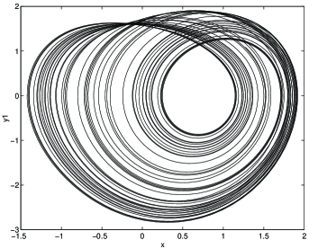
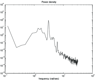
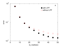
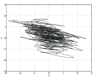
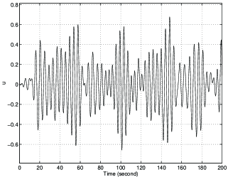
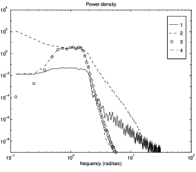
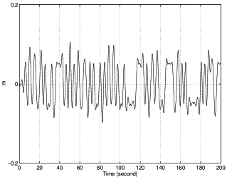
where is an impulse response function of the channel, and signal denotes linear convolution. The chaotic attractor for the system (3),(9),(13) on -plane is shown in Figure 1. The power spectrum of the -component of the driving system is shown in Figure 2. In Fig.3 we show the rms synchronization error as a function of the cutoff frequency . Comparing Figs.2 and 3 one can see that the synchronization errors accumulate quickly and become significant when most of the power spectrum of the chaotic signal is still well below .

Two different approaches have been proposed to cope with channel distortions in order to preserve synchronization of chaotic oscillators. Both these methods have an advantage that ideally they allow for exact synchronization without affecting the structure of chaotic attractors. The first scheme [25, 28, 29] involves learning the channel response function and building an inverse filter, (see Figure 4a). Apparently, this method requires that channel distortions are invertible, and the inverse filter is stable, which in not necessarily true in general. It also is very sensitive to noise in the channel. Indeed in the presence of noise the “restored” signal will have a form ( denotes random noise), and so the noise outside the passband of the filter will be amplified by the inverse filter .


The second method due to Carroll[26] employs augmenting the chaotic signal filtered be the channel, by a signal of the decoder passed through a complimentary band-stop filter
| (15) |
(see Figure 4b). In this case the filter response function also must be learned at the receiving end. As compared to the previous method, there is no filter inversion and associated with it problems of filter instability and noise amplification. As Carroll[26] has shown for a different system, for mild channel distortions (first-order filter) exact chaos synchronization can be achieved with this type of driving, however the conditional Lyapunov exponent characterizing stability of the synchronized state is less (by magnitude) than in the no-filter case. Clearly, it is the last term in (15) which provides a positive feedback in the response system and causes the reduction of stability. Now, the question remains of how one can use this method for transmitting information masked by the chaotic signal. Carroll[26] proposed simply to add an information component to the chaotic signal as in [11], and recover the information by observing the synchronization error at the response system. However this method does not yield good signal recovery even for a prefect channel, and cannot be used for high-quality transmission. In the next section we discuss the possibility of combining Carroll’s method [26] with a more sophisticated scheme [22, 21] of signal transmission.
III Communication with chaotic signals - channel compensation


In this section we consider information transmission using chaotic masking in the presense of channel distortions. The original method [16] of signal transmission with chaos is illustrated by Figure 5a. The message is injected into the feedback loop of the driving system and is recovered at the decoder by subtracting the output of the chaotic transformer (CT) from the transmitted signal . Without channel distortions this method yields exact recovery of the message after an initial transient. Let us first try to apply this method to the scheme of Fig.4b (see Figure 5b). At the response system, the message is recovered by subtracting the filtered feedback signal from the received signal . Unfortunately, when channel distortions are present, recovered signal remains corrupted because the symmetry between the encoder and decoder is broken. The decoder receives a sum of the filtered chaotic signal with the filtered message, whereas the encoder is fed by the unfiltered message. We illustrate this asymmetry by attempting to transmit a sine wave from the driving to the response system (9),(13) with the first-order filter (14) with a cutoff frequency rad/sec simulating the communication channel. In Figure 6 the rms recovery error relative to the standard deviation of the information signal is shown as a function of the signal frequency . For small , the filter does not affect the information signal and so the quality of recovery is high. However, for higher frequencies (which are still within the passband of the channel) the filter starts to affect the amplitude as well as the phase of the transmitted information signal and recovery error grows rapidly. Moreover, the distorted information signal can even break synchronization between the transmitter and receiver. The large peak near 1.6 rad/sec is due to a resonance between the sinusoidal signal and the chaotic oscillator.

The only possible way to provide an exact synchronization when the information component is present is to learn the channel transfer function at the transmitter and, using a matched filter, pre-process the information signal accordingly before injecting it into a feedback loop of the encoder. The block-diagram of this modification is shown in Figure 5c. The decoding procedure which is the same as in Figure 5b, yields a filtered message or exactly the same signal as one could possibly receive without mixing it with a chaotic component. Numerical simulations show that indeed the recovery error remains within the accuracy of the integrator (10-10 for signal frequencies throughout the passband of the channel). Thus, pre-processing of the information signal cures the problem of asymmetry in the encoder-decoder and yields exact synchronization and signal recovery. However, as was noted before, this method does not prevent the instability which may occur due to the compensating signal in the feedback loop of the response system.
IV Communication with chaotic signals – narrow-band chaotic system design


In the previous section we described a method of communication with chatic signals over a band-limited channel based on matching the system properties with the properties of the channel. The advantage of this method is that it preserves the structure of the original chaotic attractor for arbitrary channel response functions. Unfortunately, this method does not guarantee the stability of chaotic synchronization due to the feedback in the second system. Moreover, this kind of channel compensation is difficult to achieve in practice, when channel parameters vary over time or the same encoded message is to be transmitted via different channels simultaneously.
A different approach to achieve the same goal is to prepare a rather narrow-band chaotic signal which would not be significantly affected by the channel distortions. If, in addition, the information message is also narrow-band, it can be recovered at the decoder without distortion. In this section we describe two methods of creating narrow-band chaotic signals.
A Method 1
The first method is shown schematically in Figure 7a. It is somewhat similar to the channel compensation method of Section II, however the filters here are independent of the channel characteristics. The -component of the encoder is divided into a filtered part and a complimentary part . The information signal is added to and then the sum is sent to the decoder. This sum is narrow-band since by assumption both the message and the filter are narrow-band. Further, the complimentary signal is added to . Therefore, the signal which is injected into the nonlinear element of the system is simply , as if there were no filter in the feedback loop. At the decoder, the -component is similarly split into the filtered part and its complimentary part . Component is added to the received signal and the sum is injected into the nonlinear element. The information signal is recovered as a difference . It is easy to see that if the transmitted signal is passed through a channel without distortion (), the message is recovered at the decoder exactly. We call this scheme narrow-band, closed-loop design (NBCL).
One advantage of this scheme is that no matter how narrow the filter is, the chaotic dynamics of the systems remains unchanged. Yet the transmitted chaotic signal can be made arbitrarily narrow. The disadvantage however is that this method again does not guarantee stable synchronization, since the component provides a closed feedback loop in the response system. Clearly, the narrower filter is, the more power is passed to and the synchronization becomes less stable. Hence, the interplay of these two counteracting factors determines the quality of transmission.
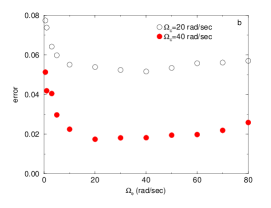
We applied this method to a chaotic encoder and decoder described by Eqs.(3),(6),(14). In the feedback loops of the oscillators we used a 4-th order low-pass elliptic filter with a stopband attenuation of 10 dB, passband gain of 0.6 and the cutoff frequency which was adjusted in order to optimize the performance of the transmission for a given channel. Figure 8a compares the rms error for transmission of the sine wave with 0.5 rad/sec with the case when no filtration is applied to the transmitted chaotic signal. For relatively high cutoff frequencies of the channel pre-filtration yields certain improvements which however vanishe for lower . The reason for this is that it is impossible to reduce the cutoff frequency of the LP filters below some value as the synchronization becomes unstable for low , and therefore the pre-filtration gives no improvement. In Figure 8b this effect is illustrated by the dependence of the rms error on the cutoff frequency of the LP filters for two values of the cutoff frequency of the channel filter . The error initially drops with due to reduction of channel distortions, but then rises due to the instability of synchronization with respect to high-frequency components.
B Method 2
As we mentioned above, method 1 (NBCL) guarantees chaotic behavior of both driving and response systems for any filters used in their feedback loops, but it does not guarantee the synchronization between encoder and decoder. It is desirable to couple two chaotic system by a narrow-band signal and still have a robust chaotic synchronization. This goal can be achieved by changing the structure of chaotic oscillators in such a way that one of its internal variables is itself narrow-band, and therefore the decoder can be made open-loop and so unconditionally stable. We call this design narrow-band, open-loop (NBOL).
A natural approach to this end is to introduce a narrow bandpass filter in the feedback loops of both oscillators but eliminate compensating feedback loops (Figure 7b). In Eqs.(3), (6) this method corresponds to choosing . Such filtering however affects the dynamics of the systems and can in principle destroy its chaotic attractor. In order to maintain chaos, one needs to have very strong nonlinearity (function ) in the system, so the narrow-band signal generates many spectral components which in turn interact with other system variables. In numerical simulations, we chose , and parameter characterizes the strength of nonlinearity. In our numerical simulations we used . In the feedback loops fourth-order Butterworth bandpass filters are placed (center frequency 1.5 rad/sec, bandwidth 0.5 rad/sec). The chaotic attractor of this system in looks rather complicated (see Figure 9), but the variable at the output of the filter is indeed narrow-band (Figure 10). We coupled two such chaotic systems via a channel which is simulated by the low-pass sixth-order Chebyshev type II filter with cutoff frequency rad/sec and 40 dB attenuation in the stopband. We transmitted two types of signals using this system. First, a sinusoidal signal which frequency coincides with the center frequency of feedback filters, was injected in the encoder. The restored signal and the recovery error are shown in Figure 11a,b. One can see that the signal recovery is indeed very good. For comparison, we show in Figure 11c the recovered signal for this system without bandpass filters in the feedback loops. The “recovered” signal is not even close to the expected sine wave.

We also carried a number of tests involving transmission a pseudo-random binary sequence of 1 and -1 using a pulse-band modulation
| (16) |
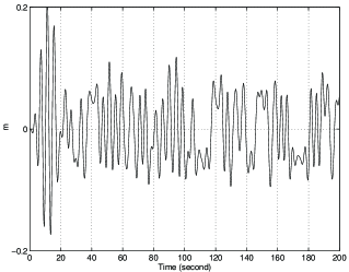
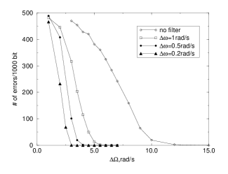
for various filters in the feedback loops and in the channel. Function was chosen to minimize intersymbol interference at the demodulating stage, and sec. In Figure 12, the power spectrum of the input signal is shown together with the power spectra of the component of the encoding system, variable which is sent through the channel, and variable which is received at the decoder, for =4 rad/sec. The time series of the modulated signal is shown in Figure 13a. The recovered signal (starting from initial transient) at the decoder is shown in Figure 13b. After demodulating this signal we computed error rate per 1000 bits for a number of values of and . This data is presented in Figure 14. For comparison, we also computed the error rate for the case when there is no filter in the feedback loops of the systems. It is easy to see that the using filters in the systems allows to reduce drastically the error rate once the signal fits into the channel passband.
V Experimental Results
As a generator of chaos we used an analog nonlinear circuit which in its basic design consists of two input-output elements, nonlinear converter (NLC) and a linear feedback (LFB), see Fig. 15. The details about implementation of NLC and LFB can be found in the Appendix. Being connected in a loop, NLC and LFB give rise to self-sustained oscillations. By judicious selection of the nonlinearity and parameters of the linear feedback one can achive generation of chaotic oscillations. To design chaotic encoder and decoder on the basis of this chaos generators we use the method proposed in [16] (see Fig.5a).


To model limited bandwidth of the communication channel we connected the encoder and decoder through a second-order low-pass VCVS active filter, see Appendix for details. In the diagrams Fig 5 this filter is labeled CHF. Parameters of the filter were selected to make a Bessel filter [30]. As a control parameter of the filter we use its cutoff frequency, measured at -3dB.
In the experiments we compared two schemes of chaos communication. The first is the original scheme implemented with open-loop chaotic decoder, see Fig 5a. The second one is the modified scheme Fig.7b that utilizes low-pass filters (LPF) to design the narrow bandwidth signal in the feedback of the chaos generator. To recover the message in the modified scheme we used a matched narrow-band open-loop (NBOL) chaotic decoder, see Fig.7b. The diagram of LPF is presented in the Appendix. Parameters of the filters were selected to make Chebyshev filter with the cutoff frequency =300Hz measured at -2dB. Chaotic attractors generated by the chaotic encoders of the original and the modified schemes with are shown in Fig. 16 a and b, respectively. Variable is the voltage measured at the output of LFB, and variable is the voltage across the capacitor C1 in the LFB, see Appendix A.
The main goal of the experiment was to measure the quality of synchronization as a function of the cutoff frequency of filter CHF. For this purpose, it is expedient to apply , and measure and . Using these waveforms sampled at 10 KHz we calculated relative values of the maximal deviation, , and standard deviation
| (17) |
Both these characteristics are normalized with respect to the parameters of the driving signals. These errors as functions of the cutoff frequency of the channel are shown in Figure 17. The plots clearly how demonstrate that using additional filters in the encoder and decoder can significantly reduce errors caused by degrading the chaotic signal in the limitied bandwidth channel In the case of NBOL errors becomes significant only when the channel has the cutoff frequency less than 4 kHz. For the broader channel the errors are due to the slight mismatch between the parameters of the encoder and decoder.
Since in the considered method of chaos communication the message does not distroy the symmetry between encoder and decoder, the results of error evaluation can also be applied, to some extent, to assess the quality of communication (). However, when the width of the spectrum of the information signal becomes comparable with the bandwidth of the channel the errors will significantly increase.

To demonstrate the feasibility of the communication with NBOL through the narrow bandwidth channel we used voice signal as and measured , and simultaneously. Figure 18 shows the results of the measurements obtained for the CHF with . Although one can notice imperfections of the recovered signal, the quality of the communication is pretty good. Note that for this cutoff frequency of the channel filter the standard scheme (without LPF) does not yield any meaningful signal recovery (cf. Fig. 17).

VI Conclusions
In this work we have explored various possibilities of transmitting analog information masked by a chaotic signal through a band-limited channel. Two main classes of systems are considered. First (adaptive) class corrects the channel distortions either using inverse filter at the receiver, or augmenting the transmitted signal by the chaotic signal generated by the decoding chaotic system passed through a complimentary matched filter. Both these approaches suffer from potential instabilities leading to the poor signal recovery.
The second class is based on modification of the structure of the chaotic signal before sending it through the channel, so it is by construction made suitable for undistorted transmission. This approach does not require learning the channel characteristic and can provide robust signal transmission. We demonstrated in numerical simulations and experiments with electronic circuits that the quality of signal recovery improves greatly as compared to transmission with wide-spectrum chaotic signals.
VII Acknowledgments
We are grateful to H.Abarbanel and M.M.Sushchik for helpful discussions. This work was supported in part by the U.S. Department of Energy under contract DE-FG03-95ER14516, and in part by the U.S.Department of the Air Force (SBIR, contract F19628-96-C0076).
VIII Appendix: Elements of the Experimental Setup
This Appendix contains the diagrams of the circuits used to build the chaos generator, auxiliary filters and the model of band-limited communication link.
To build the generator of chaos we used the loop type oscillator design [31]. This design employs serial connection of input-output stable elements. When such elements are connected into the loop, see Fig 15 the whole system can become a generator of self-sustained oscillations. By selecting characteristics of the input-output elements one can always achive the regime of chaos generation. In our experiments we used two input-output elements: nonlinear converter (NLC) and linear system which forms a linear feedback (LFB) of the oscillator.


The diagram of the NLC is shown in Fig. 19. Symmetric nonlinear characteristics of the converter are implemented with two multipliers AD633 and diod D1. Resistor R1 is used to supply 9.3V at the offset Z of the first multiplier. Variable resistor was used to select the desired regime of oscillations ( specifies the value of resistance between the ground and terminal of the OP-amplifier.
The circuitry of the linear part of the chaotic oscillator is shown in Fig. 20. It uses RC and resonant circuits to create sufficient number of degrees of freedom (dimension of the phase space) required for chaotic dynamics. In addition to that, LFB supplies a second order high-pass filter. This filter is used to eliminate DC components of the chaotic signal which is used as communication signal. In experiments the value of the resistor R1 was set at 1.01 KOhm.
As the low-pass filters in the modified chaos generator and the filter in the model of communication channel we used the second order filter which diagram is shown in Fig. 21. For LPF we used the filter with the following parameters: C5=C6=95.4 nF, R7=R8=6.11 KOhm, R9=24.7 KOhm, and R10=27.6 KOhm. For CHF we set R7=R8=22.3 KOhm, R9=50 KOhm, and R10=13.4 KOhm. The cutoff frequency was selected by capacitors C5=C6. Summation and subtraction were implemented using standard schemes of summing and differential amplifiers[30].
REFERENCES
- [1] H.Fujisaka and T.Yamada, ”Stability theory of synchronized motion in coupled-oscillator systems.” Progr. Theor. Phys., vol. 69, pp. 32-47, 1983.
- [2] A.S.Pikovsky, ”On the interaction of strange attractors.” Z.Phys. B - Condensed Matter, vol. 55, pp. 149-154, 1984.
- [3] V.S.Afraimovich, N.N.Verichev, and M.I.Rabinovich, ”Stochastic synchronization of oscillation in dissipative systems.” Radiophys. Quantum Electron., vol. 29, pp. 795-803, 1986.
- [4] A.R.Volkovskii and N.F.Rulkov, ”Experimental study of bifurcations at the threshold for stochastic locking.” Sov. Tech. Phys. Lett., vol. 15, pp. 249-251, 1989.
- [5] L.M.Pecora and T.L.Carroll, ”Synchronization in chaotic systems.” Phys. Rev. Lett., vol. 64, pp. 821-824, 1990.
- [6] H.G.Winful and L.Rahman, ”Synchronized chaos and spatiotemporal chaos in arrays of coupled lasers.” Phys. Rev. Lett., vol. 65, pp. 1575-1578, 1990.
- [7] M.Ogorzalek, ” Taming chaos. I. Synchronization.” IEEE Trans. Circuits Syst. I, vol. 40, pp. 693-699, 1993.
- [8] R.Roy and K.S.Thornburg, ”Experimental synchronization of chaotic lasers.” Phys. Rev. Lett., vol. 72, pp. 2009-2012, 1994.
- [9] B.Schneier, Applied Cryptography, J.Wiley and Sons, N.Y., 1996.
- [10] T.L.Carroll and L.M.Pecora, ”Cascading synchronized chaotic systems.” Physica D, vol. 67, pp. 126-140, 1993.
- [11] K.M. Cuomo and A.V.Oppenheim, ”Circuit implementation of synchronized chaos with applications to communications.” Phys. Rev. Lett., vol. 71, pp. 65-68, 1993.
- [12] L.Kocarev, K.S.Halle, K.Eckert, L.O.Chua and U.Parlitz, ”Experimental demonstration of secure communications via chaotic synchronization.” Int. J. Bifurcation Chaos, vol. 2, 709-713, 1992.
- [13] H.Dedieu, M.P.Kennedy, and M.Hasler, ” Chaos shift keying: modulation and demodulation of a chaotic carrier using self-synchronizing Chua’s circuits.” IEEE Trans. Circuits Syst., vol. 40, pp.634-642, 1993.
- [14] K.Murali and M.Lakshmanan, ” Transmission of signals by synchronization in a chaotic Van der Pol-Duffing oscillator.” Phys. Rev. E, vol. 48, pp. R1624-1626, 1993.
- [15] Y.H.Yu, K.Kwak, and T.K.Lim, ”Secure communication using small time continuous feedback.” Physics Letters A, vol. 197, pp. 311-316, 1995.
- [16] A.R. Volkovskii and N.F.Rulkov, ”Synchronous chaotic response of a nonlinear oscillator system as a principle for the detection of the information component of chaos.” Tech. Phys. Lett., vol. 19, pp. 97-99, 1993.
- [17] K.S.Halle, C.W.Wu, M.Itoh, and L.O.Chua, ”Spread spectrum communication through modulation of chaos.” Int. J. Bifurcation Chaos, vol. 3, pp. 469-477, 1993.
- [18] D.R.Frey, ” Chaotic digital encoding: an approach to secure communication.” IEEE Trans. Circuits Syst. II, vol. 40, pp. 660-666, 1993.
- [19] C.W.Wu, and L.O.Chua, ” A simple way to synchronize chaotic systems with applications to secure communication systems.” Int. J. Bifurcation Chaos, vol. 3, pp. 1619-1627, 1993.
- [20] U.Parlitz and L.Kocarev, ”General approach for chaotic synchronization with applications to communication.” Phys. Rev. Lett., vol. 74, pp. 5028-5031, 1995.
- [21] U.Feldmann, M.Hasler, and W.Schwarz, ”Communication by chaotic signals: the inverse system approach.” Int. J. of Circuit Theory and Applications, vol. 24, pp. 551-579 (1996).
- [22] U.Parlitz, L.Kocarev, T.Stojanovski, and H.Preckel, ”Encoding messages using chaotic synchronization.” Phys. Rev. E, vol. 53, pp. 4351-4361, 1996.
- [23] J.E.Savage, ”Some simple self-synchronizing digital data scramblers.” The Bell System Technical Journal, pp. 449-487, 1967.
- [24] P.Ashwin, J.Buescu, and I.Stewart, ”From attractor to chaotic saddle: a tale of transverse instability.” Nonlinearity, vol. 9, pp. 703-737, 1996.
- [25] Carroll, T.L.,”Synchronizing chaotic systems using filtered signals.” Phys. Rev. E, vol. 50, pp. 2580-2587, 1994.
- [26] Carroll, T.L., ”Communicating with use of filtered, synchronized, chaotic signals.” IEEE Transactions on Circuits and Systems I: Fundamental Theory and Applications, vol. 42, pp. 105-110, (1995).
- [27] Carrol, T.L. and Pecora, L.M., ”The effect of filtering on communication using synchronized chaotic circuits.” in: 1996 IEEE International Symposium on Circuits and Systems. Circuits and Systems Connecting the World, ISCAS 96, New York, NY, USA: IEEE, 1996. pp. 174-177, vol.3.
- [28] L.O.Chua, T.Yand, G.-Q.Zhong, and C.W.Wu, ”Synchronization of Chua’s circuits with time-varying channels and parameters.” IEEE Trans. Circuits and Systems - I, vol.43, pp. 862-868, 1996.
- [29] A.V.Oppenheim, K.M.Cuomo, R.J.Baron, and A.E.Fredman, ”Channel Equalization for Communication with Chaotic Signals.” in Chaotic, Fractal and Nonlinear Signal Processing, R.A.Katz, Ed., AIP Press, 1996, pp.289-301.
- [30] P.Horowitz and W.Hill,The Art of Electronics, Cambridge University Press, 1980.
- [31] A.S.Dmitriev, A.I.Panas, and S.V.Starkov, ”Ring oscillating systems and their application to the synthesis of chaos generators.” Int. J. of Bif. and Chaos, vol. 6, pp. 851-865, 1996.