Enabling Concepts for a Dual Spacecraft Formation-Flying Optical Interferometer for NASA’s ST3 Mission
Abstract
We present the enabling concept and technology for a dual spacecraft formation-flying optical interferometer, to be launched into a deep space orbit as Space Technology 3. The combiner spacecraft makes use of a nested cat’s eye delay line configuration that minimizes wavefront distortion and stores 20 m of optical pathlength in a package of m length. A parabolic trajectory for the secondary collector spacecraft enables baselines of up to 200 m for a fixed 20 m stored delay and spacecraft separations of up to 1 km.
keywords:
instrumentation: interferometers — techniques: interferometric — space vehicles: instruments1 Introduction
The last 15 years has seen considerable progress in the conception and development of ideas for multi-spacecraft optical interferometers. Stachnik, Melroy, and Arnold (1984) first laid out the conceptual framework for an orbiting Michelson interferometer, and the following year the European Space Agency devoted a colloquium to spacecraft arrays of this type. Particular emphasis in a number of studies (Johnston & Nock 1990; DeCou 1991) was placed on the choice of orbits to minimize fuel usage and provide maximal UV coverage. DeCou (1991) described a family of orbits near geostationary which were particularly efficient in this respect.
In the early 1990’s a coherent effort began at the NASA/Caltech Jet Propulsion Laboratory to develop a consistent and detailed design for a three-spacecraft Michelson interferometer known initially as the Separated Spacecraft Interferometer (SSI; Kulkarni 1994), and then as the New Millenium Interferometer (NMI; McGuire & Colavita 1996; Blackwood et al 1998) because of its alignment with NASA’s New Millenium Technology program, in which it was scheduled as Deep Space 3 (DS3).
However, funding constraints eliminated the original three-spacecraft baseline design in late 1998 and a de-scoped version involving somewhat reduced capability and requiring only two spacecraft, was adopted. The new mission, known as Space Technology 3 (ST3) due to re-alignment of the parent NASA program, has moved into a prototype construction phase, with launch now set for 2005.
In this report we describe the primary enabling concepts for the dual spacecraft system, which combine specific choices of array geometry with a novel fixed optical delay line capable of supporting a continuously variable interferometer baseline from 40 to 200 m. The next section describes the choice of geometry, followed by a section describing the overall optical layout, and the fixed delay line. A related paper in this volume (Lay et al.) describes in detail the operation of the interferometer system.
2 Observing Geometry
2.1 Original dual-spacecraft concept

Before the initial three-spacecraft configuration for DS3 was adopted as the working design, a variety of different configurations were considered which gave various levels of technology demonstration with respect to a formation–flying multiple spacecraft interferometer. One of these proposed early configurations was in fact a dual–spacecraft system (Folkner 1996). The basic geometry of this configuration is shown in Figure 1. Here the collector spacecraft (which acts simply as a moving relay mirror) travels along a parabolic trajectory with the combiner spacecraft at the focus of the parabola, which we choose as the origin in this plot. The combiner spacecraft then carries a fixed optical delay line which compensates for the additional pathlength that the collector spacecraft produces. This is indicated schematically by showing the fixed delay line as if it were reflecting off another relay mirror at the surface of the reference parabola, thus ensuring equal delay in the two arms of the interferometer.
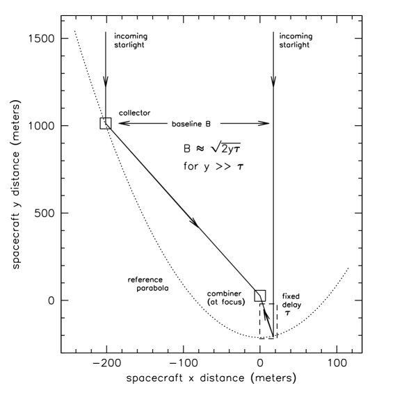
For the pictured geometry, the collector spacecraft position must satisfy:
| (1) |
where coordinate is defined as the projected baseline , and the total fixed delay carried by the combiner spacecraft is . In the case of Fig. 1 the -position of the collector spacecraft was always negative with respect to the combiner for simplicity in the relay optics. Equation (1) then determines the required collector spacecraft position for a given projected baseline
| (2) |
For the configuration of Fig. 1, the fixed delay is m, and the maximum baseline (at ) is then also 100 m.
The difficulty with this approach is the requirement that the combiner spacecraft must carry a 100 m fixed delay line in a very compact configuration, of order 1-2 m in overall length. This amount of delay is not easily achievable in a broad-band system (450-1000 nm) as was planned for DS3. Approaches involving reflections between opposing spherical or flat mirrors typically produce too much wavefront distortion, absorption, and scattering losses to be useful for a white light interferometer. Alternatives such as the use of optical fiber also do not afford the broadband single-mode operation required for a delay line.
2.2 Modified approach
Figure 2 shows a modified approach to the two spacecraft system in which a much shorter fixed delay line can be utilized. Here the spacecraft configuration entails a collector spacecraft position which moves along the reference parabola above the combiner spacecraft with respect to the source direction. Referring to equation (2) above, when . When exceeds the fixed delay , the collector spacecraft -value then becomes positive. For ,
| (3) |
thus the interspacecraft distance grows quadratically with baseline.
For the de-scoped NASA mission ST3, preliminary design considerations indicated that a fixed delay line of m stored delay was achievable within the constraints of spacecraft size and instrument visibility budget. In a later section we provide details of the fixed delay line design. Using m, and the additional constraint of km imposed by formation–flying requirements, ST3 is able to achieve a maximum interferometer baseline of about 200 m.
3 Optical Design
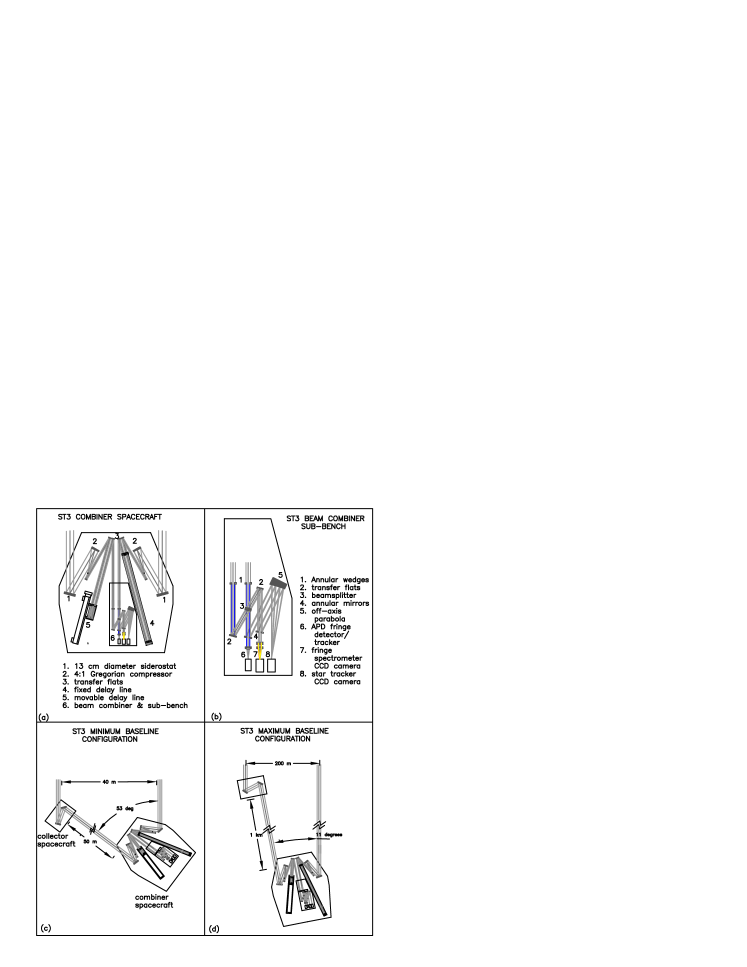

Figure 3 indicates schematically the optical design for ST3 in the adopted dual spacecraft configuration. The optical train is almost completely planar throughout the system, and employs an athermalized ultra-stable composite optical bench. In the combiner spacecraft (which will function as a standalone fixed-baseline interferometer) a pair of outboard siderostats feed into an afocal gregorian compressor with a 1 arcmin fieldstop at the internal focus.
The 12 cm incoming beams are then compressed to 3 cm and fed into the delay lines, one fixed and one movable. After this the beams enter the beam combiner. An outer 0.5 cm annular portion of each beam is stripped off for guiding, and the central 2 cm portion of the beam is used for fringe tracking (using a single-element avalanche-photodiode detector in one of the combined beams). The other combined 2 cm beam is dispersed in a prism and integrated coherently on an 80 channel CCD fringe spectrometer.
3.1 Fixed delay line
Perspective and schematic views of the fixed delay line are shown in Fig. 4. The design employs 3 nested cat’s eye retroreflectors, two of which are in a Cassegrain configuration and the third a Newtonian. As noted in the plot, the optics are very slow, giving large depth of focus and minimal impact on wavefront distortion. Three of the 13 reflections occur at foci and have little wavefront effect. However, due to the large magnification of the system, focal plane flats must be sized generously to match field of view requirements.
Acknowledgements.
We thank M. Shao and M. Colavita for their invaluable suggestions & support of this work. The research described here was carried out by the Jet Propulsion Laboratory, California Institute of Technology, under a contract with the National Aeronautics and Space Administration.References
- [1] lackwood, G.B., Dubovitsky, S., Linfield, R.P., and Gorham, P. W., 1998, Proc. SPIE 3350 (1), 173.
- [2] eCou, A. B., 1991, Journ. Astronaut. Sci., 39 (3), 283.
- [3] olkner, W. M., 1996, JPL Interoffice memo. 335.1-96-029.
- [4] ohnston, M. D., & Nock, K. T., 1990, in Proc. Tech. for Opt. Interferom. from Space, (Pasadena: JPL).
- [5] ulkarni, S. R., 1994, Prop. for New Mission Concepts in Astroph., Caltech.
- [6] ay, O. P., Blackwood, G. H., Dubovitsky, S., Gorham, P. W., and Linfield, R. P., 1999, this volume.
- [7] cGuire, J. & Colavita, M., 1996, NMI Prelim. Design Rev. A, JPL Interoffice Memorandum.
- [8] tachnik, R., Melroy, P., & Arnold, D., 1984, Proc. SPIE 445, 358.