Abstract
A new optical speckle interferometer for use at the 2.34 meter Vainu Bappu Telescope (VBT), at Vainu Bappu Observatory (VBO), Kavalur, India, has been designed and developed. Provisions have been made for observation both at the prime focus (f/3.25), as well as at the Cassegrain focus (f/13) of the said telescope. The technical details of this sensitive instrument and the design features are described. An interface between the telescope and the afore-mentioned interferometer is made based on a concept of eliminating the formation of eddies due to the hot air entrapment. The performances of this instrument has been tested both at the laboratory, as well as at the Cassegrain end of the telescope. It is being used routinely to observe the speckle-grams of close-binary (separation 1 arc second) stars. The size of the Fried’s parameter, ro, is also measured.
Key words: Interferometer, Speckle Imaging, Image Reconstruction, Seeing
Section 1 Introduction
Speckle interferometric technique (Labeyrie, 1970) has made a major break through in observational astronomy by counteracting the effect of atmospheric turbulence on the structure of stellar images, allowing measurements of a wide range of celestial objects (Barlow et al., 1986, Wood et al., 1987, Afanas’jev et al., 1988, McAlister, 1988, Ridgway, 1988, Ebstein et al., 1989, Foy, 1992, Saha et al., 1997a, Saha and Venkatakrishnan, 1997). The principle of this technique is described in detail in the literature (Dainty, 1975). A new instrument based on the above technique has been developed to operate at both the foci, prime (f/3.25), as well as Cassegrain (f/13) of the 2.34 meter Vainu Bappu Telescope (VBT) at Vainu Bappu Observatory (VBO), Kavalur, India. Since the afore-mentioned interferometer is a very sensitive instrument, any inaccuracies will lead to erroneous conclusion of the observations. Therefore, emphasis was given on the accuracies of the mechanical mounts and housing so as to ensure the optical path precisely. Most of the critical mounts were machined out of a solid piece. Care is taken in the design analysis and manufacturing to get required dimensional and geometrical accuracies. The salient features of important elements are described in this paper. Finally, we present the size of ro, measured from the speckle-grams of -Andromeda obtained with this interferometer at the VBT, Kavalur.
Section 2 Design Features
2.1 Optical Design
Figure 1 shows the optical design of the speckle camera system. Provisions have been made in the design to observe at both the foci of the 2.34 VBT. The wave front falls on the focal plane of an optical flat made of low expansion glass with a high precision hole of aperture (350 ), at an angle of 15o on its surface (Saha et al., 1997). The image of the object passes on to the microscope objective through this aperture, which slows down the image scale of this telescope to f/130. A narrow band filter is placed before the detector, to avoid the chromatic blurring. The surrounding star field of diameter 10 mm, gets reflected from the optical flat on to a plane mirror and is re-imaged on an intensified CCD, henceforth ICCD, (Chinnappan et al., 1991).

2.2 Mechanical Design Requirements
The instrument has been designed with the help of the Computer Aided Design and analysis techniques and manufactured accurately on precision machine tools. The instrument poses the following requirements. The instrument should primarily be light in weight besides being rigid when subjected to bending loads arising out of multiple orientations of the telescope. The deflection of the instrument should be minimum under its own weight, as well as when it is fitted with all accessories required for observation. Provisions for fine focusing of the image is to be incorporated for better resolution and clarity in observation. Besides these, it has to be provided with linear motion systems with no rotation of the optical elements and rigid locking of the lens position. The instrument should be aloof from temperature effects. The instrument is made of Martensitic Stainless Steel (SS410), a material with low co-efficient of linear expansion (about half that of normal steel).
2.2.1 Design Analysis
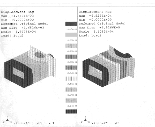
Since the optical enclosure of the interferometer has to support various mounts and the detector without any deflection in various orientations of the telescope, before arriving at the final configuration and sizes, finite element method (FEM) was used to analyze (Zienkiewicz, 1967) as well as to have prior information about the deflections, stress, flexure etc. of the enclosure. For structural analysis, Pro-mechanica software has been used for optimizing the structural members. The analysis shows that the instrument can hold any detector or camera of 20 Kgs. weight, kept at a distance of 270mm away from the mounting flange of the interferometer undergoes a maximum deflection of 1.65. The model was analyzed for strength and deflection for a distributed load of 20 Kgs. over the span of the instrument. Deflection of only 0.7 was observed. Figure 2 shows the FEM model of the speckle interferometer. It depicts the analysis carried out for two kinds of loads in the two windows. Left window shows the deformation pattern for load 1 and right window shows deformation pattern for load 2. The grey-scale blocks in the picture indicate the extent of deformations at individual places in the model of the interferometer.
2.3 Elements of the Interferometer
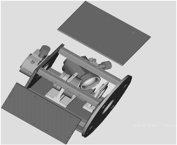
An overall view of the interferometer is shown in Figure 3. It can be seen that the instrument basically consists of an optical enclosure, which houses the following assemblies. (i) Microscope assembly, (ii) Filter assembly, (iii) Detector mount, (iv) Guiding system.
2.3.1 Optical Enclosure
The instrument has been conceived as a box made of two end plates of thickness 8mm and joined by means of struts of section 22mm square. The struts have been machined from cylinders of 25mm diameter and required length. The struts are provided with spigots of 18mm diameter at ends for locating the end plates. The diameters of 25mm and 18mm at both ends are ground between centers to ensure concentricity of the spigots and the main cylinder. The end plates are provided with four holes to receive the spigots and are machined together in one setting on Wire-cut Electro Discharge Machining (EDM) to assure the size and the required center distance accuracies. The end plates, when locked with the struts, form a box structure of light weight with the required strength to house the designed mounts with minimum deflection. A bottom plate has been clamped on to two of the struts and this forms the platform on which the various mounts of the microscope can be mounted. Once the reference is established parallel to the path of the wave front, the mounts can be manufactured in such a way that the lens mounting holes are at an accurate distance from their bases. In case of any error, the base of the mounts can be ground to get the required center height. Thus the plane in which the light travels through the microscope and the mirrors is maintained accurately. One of the sides has been provided with side plates shaped in such a way as to reduce overall volume occupied by the enclosure while ensuring no light leakage. The optical enclosure has been blackened to ensure that no stray light is received by the optical elements. A special process has been used to blacken the stainless steel material.
2.3.2 Microscope Assembly
The microscope mount assembly is shown in figure 4. The main body of the assembly has a base and a vertical face in which a bore has been made to receive the focal plane mirror and the microscope. The axis of the bore is maintained parallel to the base and its distance is maintained accurately like all the other mounts. The focal plane mirror mount is mounted at an angle of 15o with the axis of the aperture (350) as mentioned earlier (see section 2.1). After mounting the focal plane mirror, the aperture comes in the axis of the microscope mount. The image of the object is passed on to the microscope objective through this aperture. In the design, fine focusing arrangement has been provided to get optimum focus of the image. Accurate aligning, guiding and locating have been ensured to get an accurate straight line motion of the objective along the direction of optical axis. A rigid locking system has been provided taking into consideration that the image should not be disturbed either during or after locking. Care has also been taken to ensure that the axes of the 15o bore and the optical axes intersect at a predetermined point. A mirror cell has been conceived and designed to facilitate the focal point flat elliptical mirror ensuring its safety into consideration.
Further development of this incorporates a nano-adjusting mechanism which helps in ultra fine focusing of the microscope objective. Flexure mechanism is being used to achieve the nanometric motion of the same.

2.3.3 Detector Mount
The high speed electronic detectors are being used to record the speckle-grams of faint point source. This may be in the form of either detecting the photon events per frames up to frame rate of 50 Hz (Blazit et al., 1977, Blazit, 1986), or detecting individual photon events with time resolution of a few sec (Papaliolios et al, 1985, Durand et al., 1987, Graves et al., 1993). In this design too, we made an arrangement for fine focusing the speckles by moving the detector back and forth precisely in line with the optical axis. Locking arrangement has been provided to avoid effects of backlash. In addition, we made an arrangement for the micrometric xy movement of the detector which would ensure its position precisely. A good quality manually adjusted iris kept in front of the detector, eliminates the extraneous light. Provision for mounting different narrow band filters for observation have also been made.
2.3.4 Guiding System
The surrounding star field of a few arc min gets reflected from the elliptical mirror and falls on to the flat mirror at an angle of 30o with respect to the optical axis. The mount of the flat mirror has been relieved suitably to ensure that the image reaches from the elliptical mirror without any obstructions and image is fully received by the flat mirror. The re-imaging lens mount is designed with provisions for lens mounting, focusing and a rigid locking mechanism. The lens collects the reflected rays from the afore-mentioned optical flat and is re-imaged on to an ICCD so as to enable one to guide remotely from the Console room of the telescope.
2.3.5 Spacer Assembly
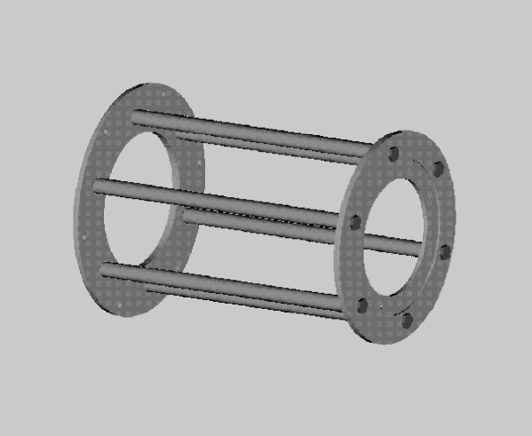
It is found that the best focus at the Cassegrain end of the 2.34 meter VBT is at a distance 570 mm away from its mounting flange. In the design of this interferometer, we have kept the focal point, the aperture (350) on the elliptical mirror, as described in section 2.1, 110mm away from the surface of the mounting flange at the Prime focus of this telescope. Therefore, it is essential to design a spacer of 450mm size, so as to enable us to observe at the Cassegrain end of the VBT. The design of the spacer has to satisfy the following requirements : light in weight, high rigidity and low deflection at various orientations of the telescope. When mounted, both the mounting diameters should be perfectly concentric to each other and it should not allow the formation of eddies that may be produced due to hot air entrapment. In order to satisfy the above requirements, spacer is designed with two plates separated by six pillars of equal height. The pillar rods have concentric spigots at both ends. These spigots are located in holes provided on pitch circle diameter concentric with respect to the reference diameters. The pillars are rigidly bolted on to the plates at both ends. This design ensures a rigid, light weight spacer which allows free movement of air and has concentric diameter plates on both ends. Figure 5 depicts the design of the spacer.
Section 3 Observations at VBT
Observations of several close binary systems (separation 1 arc sec), and of other stars, using this newly built interferometer have been successfully carried out on 29/30 November, 1996, at the Cassegrain focus of the VBT through a 5nm filter centered on H using uncooled ICCD. The image scale at the afore-mentioned focus of this telescope is magnified to 0.67 arcsecond per mm. The CCD gives video signal as output. The images were acquired at an exposure times of 20 ms using a frame grabber card DT-2861 manufactured by Data TranslationTM and stored on to the hard disk of PC486 computer. It can store upto 64 frames in a few seconds time. The interface between the intensifier screen and the CCD chip is a fibre-optic bundle which reduces the image size by a factor of 1.69. The frame grabber card digitises the video signal and resamples the pixels of each row (385 CCD columns to 512 digitised samples), by introducing a net reduction in the row direction of a factor of 1.27. These images were analysed on a Pentium PC.
Section 4 Measurement of ro
The resolution of a large telescope, limited by the atmospheric turbulence, as defined by the Strehl criterion is
| (1) |
where is the wavelength of observation and ro is the Fried’s parameter.
Hence, ro is directly related to the seeing at any place. The conventional method of measuring seeing from the star image is to measure the full width half maximum (FWHM) of a long exposure stellar image at zenith:
| (2) |
There are different methods of measuring the seeing at any given place. Through a large telescope, the size of the seeing disk is often estimated by comparing it to the known angular separation of a double star. The seeing value can be estimated by star trails too. The other qualitative method is to measure ro from the short exposure images using speckle interferometric technique. The speckle life time is an important atmospheric parameter since it describes the longest possible exposure time for recording speckle interferograms. It is an important parameter too for testing the atmospheric condition at existing and incoming astronomical sites (Vernin et al., 1991). In this technique, the area of the telescope aperture divided by the estimated number of speckles gives the wavefront coherence area , from which ro can be found by using relation,
| (3) |
Von der Lhe (1984) suggested that the squared modulus of the average observed Fourier transform should be divided by the averaged observed power spectrum. This expression depends only on the seeing conditions that prevails during the period covered by the time series and on the signal-to-noise ratio. The method may be useful for the observations of extended object where reference is not available.
If many short exposure images and their autocorrelations are summed, the summed images have the shape of seeing disk, while the summed autocorrelations contain autocorrelation of the seeing disk together with the autocorrelation of the mean speckle cell (Wood, 1985). It is width of the speckle component of the autocorrelation that provides information on the size of the object being observed.
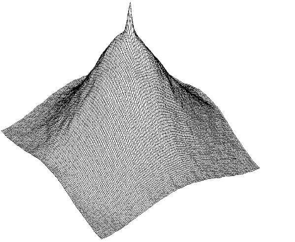
We have used the speckle interferometric technique to measure the Fried’s parameter at 2.34 meter VBT, VBO, Kavalur. 10 continuous speckle-grams of -Andromeda, were processed. Figure 6 depicts the autocorrelation of the seeing disk together with the autocorrelation of the mean speckle cell. The size of the ro is found to be the 11.44cm at the FWHM.
Section 5 Discussions and Conclusions
Optimized instruments and meticulous observing procedures are part of the important ground work for addressing the basic astrophysical problems. The new interferometer would enable one to observe many interesting objects and to map their high resolution features, taking the positional advantage of the site, at Kavalur. The latitude of this observatory (12.58o) gives us access to almost 70o south of the celestial equator, therefore, most of the observational results beyond 30o south of zenith at high latitude stations obtained earlier can be confirmed. Before arriving at the final concept of the design of this instrument, several experiments were carried out at the various telescopes (Saha et al., 1987, Chinnappan et al., 1991), as well as at the laboratory (Saha et al., 1988). Emphasis was given on the design analysis using the modern FEM technique while designing the instrument to obtain required dimensional and geometrical accuracies of the mechanical mounts and house so as to avoid erroneous conclusion of the observations.
The quality of the image degrades due to the following reasons: (i) variations of air mass X ( 1/cosZ) or of its time average between the object and the reference, (ii) seeing differences between the modulation transfer function (MTF) for the object and its estimation from the reference, (iii) deformation of mirrors or to a slight misalignment while changing its pointing direction, (iv) bad focusing, (v) thermal effect from the telescope etc. (Foy, 1988). Measurement of ro is of paramount importance to estimate the seeing at any astronomical site. Systematic studies of this parameter would enable to understand the various causes of the local seeing, for example, thermal inhomogeneities associated with the building, aberrations in the design, manufacture and alignment of the optical train etc. Significant improvement of the seeing was noticed during the observations of the speckles of close binaries, by introducing the afore-mentioned spacer, that does not allow the formation of eddies produced by the hot air entrapment, as an interface between the telescope and the interferometer compare to earlier observations (Saha and Chinnappan, 1998).
Acknowledgements
The authors are grateful to Prof. J C Bhattacharyya, for the constant encouragement during the progress of the work. The personnel of the mechanical division of IIA, in particular Messrs. B R Madhava Rao, R M Paulraj, K Sagayanathan and A Selvaraj provided excellent support during execution of the work. The help rendered by Mr. J R K Murthy and Y V Ramana Murthy of CMTI for the computer analysis of the design and by Dr. Indira Rajagopal of National Aerospace Laboratory, Bangalore for the black chrome plating are also gratefully acknowledged.
References
- Afanas’jev, V.S., Balega, I.I., Balega, Y.Y., Vasyuk, V.A. and Orlov, V.G., 1988, Proc. ESO-NOAO Conf., High Resolution Imaging by Interferometry, ed., F. Merkle, Garching bei Mnchen, FRG, 127.
- Barlow, M.J., Morgan, B.L., Standley, C. and Vine, H., 1986, M N R A S., 223, 151.
- Blazit, A., Bonneau, D., Koechlin, L. and Labeyrie, A., 1977, Ap. J., 214, L79.
- Chinnappan, V., Saha, S.K. and Faseehana, 1991, Kod. Obs. bull., 11, 87.
- Dainty, J.C., 1975, Laser speckle and related phenomena, ed., J.C. Dainty, Springer-Verlag, 255.
- Durand, D., Hardy, E. and Couture, I., 1987, Astron. Soc. Pacific., 99, 686.
- Ebstein, S., Carleton N.P. and Papaliolios, C., 1989, Ap. J., 336, 103.
- Foy, R., 1988, Proc. Instrumentation for Ground-Based Optical Astronomy - Present and future ed. L.Robinson, Springer-Verlag, NY, 345.
- Foy, R., 1992, Proc. ESO-NOAO conf. High Resolution Imaging Interferometry, ed., J.M. Beckers and F. Merkle, Garching bei Mnchen, FRG, 5.
- Fried, D.C., 1966, J. Opt. Soc. Am., 56, 1972.
- Graves, J.E., Northcott, M.J., Roddier, C., Roddier, F., Anuskiewicz, J., Monet, G., Rigaut, F. and Madec P.Y., 1993, Proc. ICO-16 Satellite Conf. Active and Adaptive Optics ed. F. Merkle, Garching bei Mnchen, Germany, 47.
- Labeyrie, A., 1970, A & A. 6, 85.
- McAlister, H.A., 1988, Proc. ESO-NOAO conf. High Resolution Imaging Interferometry, ed. F. Merkle, Garching bei Mnchen, FRG, 3.
- Papaliolios, C., Nisenson, P. and Ebstein, S., 1985, App. Opt. 24, 287.
- Ridgway, S.T., 1988, Proc. NATO-ASI, Diffraction Limited Imaging with Very Large Telescopes, ed. D.M. Alloin and J.M. Mariotti, Cargse, France, 307.
- Saha, S.K. and Chinnappan, V., 1998, ’Night Time Variations of Fried’s Parameter at VBT, Kavalur’, Communicated to Bull. Astr. Soc. Ind.
- Saha, S.K., Jayarajan, A.P., Rangarajan, K.E. and Chatterjee, S., 1988, Proc. ESO-NOAO conf. High Resolution Imaging Interferometry, ed. F. Merkle, Garching bei Mnchen, FRG, 661.
- Saha, S.K., Jayarajan, A.P., Sudheendra, G., Umesh Chandra, A., 1997, Bull, Astron. Soc. Ind., 25, 379.
- Saha, S.K., Rajamohan, R., Vivekananda Rao, P., Som Sunder, G., Swaminathan, R. and Lokanadham, B., 1997a, Bull. Astron. Soc. Ind., 25, 563.
- Saha, S.K. and Venkatakrishnan, P., 1997, Bull, Astron, Soc. Ind., 25, 329.
- Saha, S.K., Venkatakrishnan, P., Jayarajan, A.P. and Jayavel, N., 1987, Curr. Sci. 57, 985.
- Vernin, J., Weigelt, G., Caccia, J.L. and Mller, M., 1991, A & A. 243, 553.
- Von der Lhe, O., 1984, J. Opt. Soc. Am. A., 1, 510.
- Wood, P.R., 1985, Proc., A S A, 6, 120.
- Wood, P.R., Meatheringham, S.J., Dopita, M.A., and Morgan, D.M., 1987, Ap. J., 320, 178.
- Zienkiewicz, O.C., 1967, The Finite Element Methods in Structural & Continuum Mechanics, McGrawhill Publication.