Integrated optics for astronomical interferometry
Abstract
We propose a new instrumental concept for long-baseline optical single-mode interferometry using integrated optics which were developed for telecommunication. Visible and infrared multi-aperture interferometry requires many optical functions (spatial filtering, beam combination, photometric calibration, polarization control) to detect astronomical signals at very high angular resolution. Since the 80’s, integrated optics on planar substrate have become available for telecommunication applications with multiple optical functions like power dividing, coupling, multiplexing, etc. We present the concept of an optical / infrared interferometric instrument based on this new technology. The main advantage is to provide an interferometric combination unit on a single optical chip. Integrated optics are compact, provide stability, low sensitivity to external constrains like temperature, pressure or mechanical stresses, no optical alignment except for coupling, simplicity and intrinsic polarization control. The integrated optics devices are inexpensive compared to devices that have the same functionalities in bulk optics. We think integrated optics will fundamentally change single-mode interferometry. Integrated optics devices are in particular well-suited for interferometric combination of numerous beams to achieve aperture synthesis imaging or for space-based interferometers where stability and a minimum of optical alignments are wished.
Key Words.:
Instrumentation: interferometers1 Introduction
Optical long baseline interferometry is one of the upcoming techniques that will undoubtedly provide compelling, high angular resolution observations in optical astronomy. The first attempt to use interferometry in astronomy was proposed by Fizeau (1868) and achieved by Stefan (1874) on a single telescope with a pupil mask. Michelson & Pease (1921) first succeeded in measuring stellar diameters, but their interferometer was not sensitive enough to enlarge their investigation. Interferometry is a rather complex technique which needs extreme accuracies directly proportional to the foreseen spatial resolution: 1 milliarcsecond on the sky translates to 0.5 m in optical delay on a 100-m baseline. That is why modern direct interferometry started only in the 70’s with Labeyrie (1975) who produced stellar interference with 2 separated telescopes. Also interferometric experiments require very low noise detectors which became available only recently. In addition, the atmosphere makes the work even more difficult and dramatically limits the sensitivity of ground-based interferometers. Space-based interferometric missions are therefore being prepared, like the NASA Space Interferometric Mission (SIM) or the interferometry corner stone in the ESA Horizon 2000+ program: Infrared Spatial Interferometer, (IRSI).
Long baseline interferometry is based on the combination of several stellar beams collected from different apertures and is aimed to either aperture synthesis imaging (Roddier & Léna 1984) or astrometry (Shao & Staelin 1977). A number of interferometers are currently working with only two apertures: SUSI (Davis et al. 1994), GI2T (Mourard et al. 1994), IOTA (Carleton et al. 1994), PTI (Colavita et al. 1994). COAST (Baldwin et al. 1996) and NPOI (Benson et al. 1997) have started to perform optical aperture synthesis with three apertures by using phase closure techniques. The increase in the number of apertures is one of the major feature of new generation interferometers, like CHARA with up to 7 apertures (McAlister et al. 1994) or NPOI with 5 siderostats (White et al. 1994). We are on the verge of new breakthroughs with the construction of giant interferometers like the VLTI (Very Large Telescope Interferometer) by the European community which will use four 8-m unit telescopes and three 1.8-m auxiliary telescopes (Mariotti 1998), or the Keck Interferometer (Colavita et al. 1998) which will have two 10-m telescopes and four 1.5-m outriggers. They will both achieve high sensitivity thanks to their large apertures and allow the combination of more than three input beams.
We propose in this article a new technology for beam combination that is inherited from the telecom field and micro-sensor applications. This technology will answer many issues related to astronomical interferometry. The technology is called integrated optics on planar substrate, or, in short, integrated optics. The principle is similar to that of fiber optics since the light propagates in optical waveguides, except that the latter propagates inside a planar substrate. In many aspects, integrated optics can be considered like the analog of integrated circuits in electronics.
We describe in Sect. 2 the optical functions required by an interferometer. We present in Sect. 3 the principle of integrated optics, the technology and the available optical functions. Section 4 presents the concept for an interferometric instrument made in integrated optics, and touches upon future possibilities. Section 5 discusses the different technical and scientific issues of this new way of doing interferometry. Results with a first component coming from micro-sensor application will be presented in paper II (Berger et al. 1999). They demonstrate the validity and feasability of the integrated optics technology for astronomical interferometry.
2 Description of a single-mode interferometer
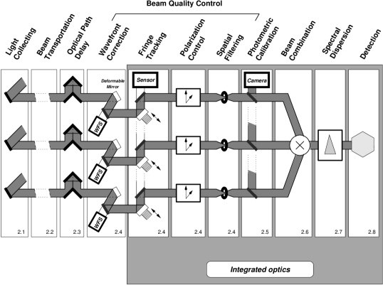
To understand where and how integrated optics can play a role in astronomical interferometry, we review the different optical functions present within an interferometer (see Fig. 1). This comes after a summary of stellar interferometry principles. All interferometers but GI2T being single-mode beam combiners (the field is limited to the diffraction pattern of each aperture), we limit our study to the single-mode field, the most appropriate mode for integrated optics.
A two-telescope stellar interferometer provides the measure of interference fringes between two beams at the spatial frequency , where is the wavelength, and the projection of the baseline vector defined by the two telescopes along the unit vector pointing to the source. The complex visibility of these fringes is proportional to the Fourier transform of the object intensity distribution (Van-Cittert Zernike theorem). Hereafter we call visibility the modulus of the degree of coherence at the spatial frequency normalized to the value at the zero frequency,
| (1) |
and phase its argument. The phase is related to the position of the photo-centroid of the source by the relation:
| (2) |
For ground-based interferometers, the source phase is corrupted by atmospheric turbulence. This prevents an absolute measurement of the source phase. However it is possible to measure the difference in source phase between two wavelengths111Phase-closure and phase-reference techniques also provide ways of retrieving this phase..
2.1 Light collecting
The stellar light is collected by each individual aperture. These apertures can be either siderostats (e.g. Mark III, PTI, IOTA) or telescopes (e.g. GI2T, VLTI, Keck Interferometer). The coverage of the spatial frequencies is usually done by carefully locating the apertures in order to take advantage of the earth rotation which induces a variation of the length and orientation of the projected baselines (super-synthesis effect). If the structure of the object does not depend on wavelength, then observing at different wavelengths is equivalent to observing at different spatial frequencies. When the apertures are movable (GI2T, IOTA, SUSI), the interferometer can cover many different baselines with different geometrical configurations.
2.2 Beam transportation
The beams coming out from each telescope must be directed toward the beam combination table. Two different techniques can achieve this transportation:
-
•
Bulk optics
Flat mirrors are usually used to carry the light from the single apertures toward the central beam combiner. Their main advantages are high throughput and low wavelength dependency. However they are sensitive to thermal and mechanical disturbance and they require many degrees of freedom to align the beams.
Two different philosophies have been developed for transportation. 1) The Coudé trains are symmetrical to prevent differential polarization rotations and phase shifts. It leads to a large number of mirrors and thus a low throughput especially in the visible. One still get residual polarization effects essentially due to optical coatings differences which are not negligible. 2) The number of optics is reduced to a minimum and the large resulting polarization effects are calibrated and corrected inside the interferometer (Sect. 2.4).
-
•
Fiber optics
Froehly (1981) and Connes et al. (1984) were the first to propose fiber optics to connect different apertures. Major efforts have been achieved in this field by Shaklan & Roddier (1987); Shaklan (1990); Reynaud et al. (1994); Reynaud & Lagorceix (1996) with silica fibers and in the 2.2 m range by Coudé du Foresto & Ridgway (1991); Coudé du Foresto et al. (1996) with fluoride fibers.
The optical fiber throughput is very high: 100-m silica fiber has a throughput of at (0.15dB/km). In addition, fibers offer some flexibility since the only degrees of freedom are located at the entrance and output of the fiber. That is one reason why Turner & Brummelaar (1997) have proposed optical fibers to combine the visible beams of CHARA. Using fibers can be significantly less expensive than bulk optics.
The several drawbacks of using optical fibers are: chromatic dispersion if the optical path through the different fibers is not matched; mechanical and thermal sensitivity (optical fibers are also used as micro-sensors); and birefringence of the material. However Reynaud & Lagorceix (1996) have shown that one can overcome most of these difficulties by controlling actively the fiber length, carefully polishing the fiber ends and by using polarization maintaining fibers.
2.3 Optical path delay (OPD)
The optical path from the beam combiner upward to the stellar source are not identical for each beam. The interferometer must equalize the pathlength at the micron-level accuracy. Furthermore the path lengths change with time and the interferometer must take into account the sidereal motion. This optical function is performed with delay lines.
The classical solution consists in a retro-reflector based on a moving chart (Colavita et al. 1991). The retro-reflector can be either a cat’s eye or a corner cube. Reynaud & Delaire (1994); Zhao et al. (1995) have proposed to stretch optical fibers to delay the optical path. Laboratory experiments showed that this type of delay lines can achieve more than 2 m continuous delay with 100 m silica fibers (Simohamed & Reynaud 1996), and about 0.4 mm continuous delay with 3.4 m fluoride fibers (Zhao et al. 1995). However in the latter case, the maximum optical path delay is somewhat limited since the fiber length is restricted to the maximal accepted stretch: Zhao et al. (1995); Mariotti et al. (1996) proposed multi-stage delay lines which perform short continuous delays by fiber stretching and long delays by switching between fiber arms of different lengths. However the differential dispersion in fibers of different length still remains a limiting factor of this technology.
Optical path modulation using silica fibers has been implemented in the ESO prototype fringe sensor unit (Rabbia et al. 1996).
2.4 Beam quality control
The control of the beam quality is essential to maintain the intrinsic contrast of the interferometer.
-
•
Wavefront correction
The stellar light goes through the atmosphere where the wavefront is disturbed. Depending on the wavelength and the size of the turbulent cell () compared to the aperture size, the incoming wavefront is corrugated and the stellar spot divided in several speckles with phase differences in the focal plane. Single-mode interferometers select only one speckle and therefore the atmospheric turbulence leads to signal losses proportional to the Strehl ratio. Using adaptive optics to correct at least partially the incoming wavefront increases the total throughput of an interferometer. The minimum wavefront correction is the tip-tilt correction used on many interferometers (IOTA, SUSI, PTI,…)
-
•
Fringe tracking
Due to the same atmospheric perturbations but at the baseline scale, the optical path between two apertures will rapidly vary. When requiring a high sensitivity like for spectral analysis, one needs to increase the acquisition time. The interferometric signal must be analyzed faster than the turbulence time scale to prevent visibility losses due to fringe blurring. The fringe tracker analyzes the fringe position and actively control a small delay line to compensate the atmospheric delay. The fringes are stabilized.
-
•
Polarization
Instrumental polarization can dramatically degrade the fringe visibility. The main effects are differential rotations and phase shifts between the polarization directions (Rousselet-Perraut et al. 1996). Even if special care is taken in designing the optical path to have the most symetrical path for each beam, in practice the incident angles are not exactly the same and the mirrors do not have the same coatings.
-
•
Spatial filtering
The incoming wavefronts propagate through a spatial filter, a geometrical device which selects only one coherent core of the beams. It can be achieved either by a micrometer-sized hole or by an optical waveguide like a fiber (Shaklan & Roddier 1988). This principle has been applied successfully to the FLUOR interferometric instrument (Coudé du Foresto 1996). The beams including atmospheric turbulence effects are then characterized by only two quantities, the amplitude and the phase of the outcoming electric field222In fact, this statement is correct only for long enough fibers ( like a few centimeters) or small hole (a few tenths of the diffraction-limited pattern).. Combined with photometric calibration, this process leads to accurate visibilities (see Sect. 2.5).
2.5 Photometric calibration
The interference signal which is measured in stellar interferometry is directly proportional to each incoming beam intensity. These intensities fluctuates because of the atmospheric turbulence. The estimation of the fringe contrast is improved when these intensities are monitored as suggested by Connes et al. (1984) and validated by Coudé du Foresto (1996). Photometric calibration combined with spatial filtering leads to visibility accuracies better than 0.3% (Coudé du Foresto et al. 1996).
2.6 Beam combination
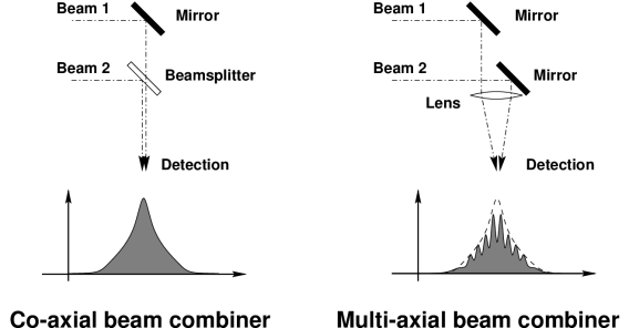
Mariotti et al. (1992) have classified the different types of beam combinations. In the single-mode case, there are two types of beam combination:
In bulk optics, the co-axial combination is performed with a beam splitter whereas the multi-axial combination is done by focusing the different beams on the same spot. In the case of multi-axial combination, the differential tilt between the beams produces fringes on the point spread function. The co-axial combination can be regarded as a particular case of the multi-axial mode where all the beams are superposed without tilts: the fringes disappears and the amplitude of the resulting spot depends on the phase difference between the two beams.
The fringe encoding is achieved, in the co-axial case, by modulating the optical path difference between the two beams which results in an intensity modulation, or, in the multi-axial case, by sampling the spatial fringes with a detector matrix333If OPD modulation is used with the multi-axial combination, then the fringes appears to move underneath the fringe envelope.. Usually if the fringes are coded in one direction, the other direction is compressed to reduce the number of pixels.
2.7 Spectral information
This function is not always implemented in existing instruments, although it is useful for two objectives: to estimate the physical parameters of the source (temperature, kinematics,…), and, to determine the position of the central fringe at zero OPD. The distance between the fringes being directly proportional to the wavelength, one can derotate the fringe phase like in Mark III and PTI (Shao et al. 1988) or to measure the group-delay like in GI2T (Koechlin et al. 1996).
The spectral information can be obtained by dispersing the fringes with a dispersive element (GI2T, PTI). Mariotti & Ridgway (1988) also suggested to apply the concept of Fourier transform spectrography to interferometry by performing double Fourier transform interferometry.
2.8 Detection
In the visible, the detectors are either CCDs or photon-counting cameras. In the infrared, for long mono-pixel InSb detectors have been used, but with the availability of array detectors with low read-out noise, interferometers started to use detector matrices.
3 Integrated optics on planar substrate
The concept of integrated optics was born in the 70’s with the development of optical communications by guided waves. A major problem of transmission by optical fibers was the signal attenuations due to propagation and the need for repeaters to reformat and amplify the optical signals after long distances. The solution offered by classical optics was unsatisfactory and Miller (1969) suggested an integrated, all-optical component on a single chip, with optical waveguides to connect them.
3.1 Principle of guided optics
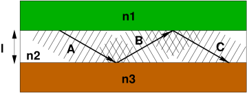
For sake of simplicity, we first consider the wave propagation of a collimated incident beam into a planar waveguide. This particular structure is formed of three step-index infinite planar layers (see Fig. 3). Light can be observed at the structure output provided that total reflection occurs at each interface and constructive interferences occur between two successive reflected wavefronts (A and C in the figure). The first condition implies that a high-index layer is sandwiched between two low-index layers and gives the range of acceptable incident angle. The second condition translates into a phase difference between the wavefronts A and C multiple of 2. Therefore the range of acceptable incident angles is no longer continuous but discrete. A single-mode waveguide is a guide which can propagate only the direction parallel to the waveguide. The core layer thickness ranges between and depending on the index difference. Multimode guide propagates beams coming from different directions.
In practice, one needs the full electromagnetic field theory to compute the beam propagation inside the waveguide. The continuity relations of the electromagnetic fields at each interface lead to the equations of propagation of guided modes (Jeunhomme 1990). Depending on the wavelength and the guide thickness ( in the Fig. 3), these equations have either no solution (structure under the cutoff frequency), either only one solution (single-mode structure) or several ones (multi-mode structure). The number of solutions also depends on the difference of refractive index between the various layers of the structure. The larger the index difference are, the better the modes are confined. These equations also allow to estimate the energy distribution profile which can be approximated, to first order, by a Gaussian function. The major part of the energy lies in the channel, but evanescent waves can interact with evanescent waves coming from other close waveguides (see the directional coupler in Sect. 3.3).
In interferometry, multi-mode guided structures cannot be used since there exist optical path differences between the various modes. In the following, only single-mode waveguides are considered.
3.2 Current technologies
3.2.1 Ion exchange
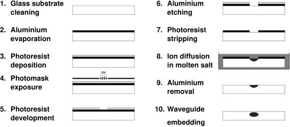
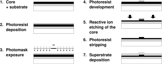
A first method to build integrated guides on planar substrate is based on glass ion exchange (Ramaswamy & Srivastava 1988; Ross 1989): the ions of a glass substrate are exchanged by diffusion process with ions (, or ) of molten salts. The local modification of the glass chemical composition increases the refractive index at the glass surface. A three-layer structure (air / ions / glass) is created and the light is vertically confined. By standard photo-masking techniques (see Fig. 4), the ion exchange can be limited to a compact area and create a channel waveguide. Since ion exchange only occurs at the surface of the glass, the last step of the process consists in embedding the guide, either by forcing the ions to migrate with an electric field or by depositing a silica layer on the waveguide. We obtain a component which guides the light like an optical fiber, the ion exchange area being the core and the glass substrate444with or without the added silica layer being the cladding. According to the ions of the molten salt, the refractive index difference can vary between 0.009 and 0.1 (see Table 1).This technology provides various components for telecom and metrology applications.
| Ions | Comments | |
|---|---|---|
| Li+ | 0.02 | High tensile stresses |
| K+ | 0.009 | Compressive stresses |
| Rb+ | 0.01 | High price |
| Cs+ | 0.04 | Slow diffusion |
| Tl+ | 0.10 | Attention for safety |
| Ag+ | 0.10 | Low thermal stability |
3.2.2 Etching technologies
Another method consists of etching layers of silicon of various indices (Mottier 1996). These layers can be either phosphorus-doped silica or silicon-nitride. Both technologies can create channels by etching layers of material, where light is confined like in an optical fiber (see Fig. 5). The channel geometry is defined by standard photo-masking techniques. According to the fabrication process, can be either high (0.5) for very small sensors, or very low (between 0.003 and 0.015) for a high coupling efficiency with optical fibers. These technologies usually provide components for various industrial applications (gyroscopes, Fabry-Pérot cavities or interferometric displacement sensors).
3.2.3 Polymers
Single mode waveguides made by direct UV light inscription onto polymers are in progress. Such a technology is still in development and the components present usually high propagation losses (Strohhöfer et al. 1998).
3.3 Available functions with integrated optics

The first two technologies provide many standard functions for wavelengths ranging between 0.5 and 1.5 (standard telecom bands). Several examples are presented (see Fig. 6):
-
1.
The straight waveguide is the simplest component.
-
2.
The curved waveguide allows some flexibility to reduce the size of integrated optics components. Its characteristics depend on the radius of curvature.
-
3.
The direct Y-junction acts as an achromatic 50/50 power divider.
-
4.
The reverse Y-junction is an elementary beam combiner similar to a beam-splitter whose only one output is accessible555The flux is lost if the incident beams are in phase opposition..
-
5.
The mirror is an Y-junction coupled with curved waveguides creating a loop. A straight transition between the Y-junction and the loop ensures a symmetrical distribution. The modes propagating through the loop in opposite directions interfere and then light goes back in the input straight waveguide.
-
6.
The directional coupler consists in two close waveguides. According to their proximity and the length of the interaction area, modes can be transfered between them and a power divider can be realized. The power ratio obviously depends on the distance between the two guides, the length of the interaction area and the wavelength.
-
7.
The characteristics of the X-crossing depend on the intersection angle. For high angles (e.g. larger than 10 degrees), the two waveguides do not interact: the crosstalk is negligible. For smaller angles, a part of power is exchanged between the two arms of the components.
-
8.
The taper is a smooth transition section between a single-mode straight waveguide and a multi-mode one. It allows light to propagate in the fundamental mode of the multimode output waveguide. The output beam is thus collimated.
4 A coin-size complete interferometer
Many functions required by interferometry (see Fig. 1) can be implemented on a single integrated optics component made from a tiny glass plate. Based on the listed available functions, one can design a beam combiner for a multi-telescope interferometer.
4.1 Beam combination
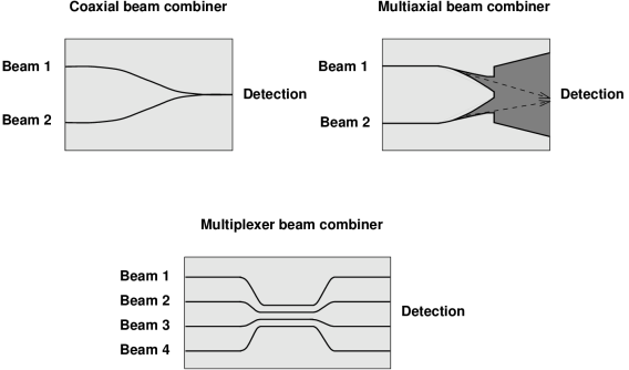
Fig. 7 displays various types of integrated optics beam combiners for two telescopes. They can easily be upgraded to the combination of a larger number of beams. We have classified these beam combiners with the same terminology as in Sect. 2.6.
A co-axial beam combiner is made of waveguide junctions. Reverse Y-junctions allow to collect only the constructive part of the interferometric signal while X-crossing junctions with small angles get the whole interferometric signal provided that asymmetric waveguides are used for the two arms. Note that directional couplers can also be used despite the narrow bandpass.
A multi-axial beam combiner is formed by individual single mode waveguides assembled by a taper that feed a planar waveguide. The light propagates freely in the horizontal direction and the beams interfere at the output of the device whereas light remains confined in the vertical direction. The fringes can be sampled on a detector.
The multiplexer has no analogs in classical optics666except if we pile up several coaxial beam combiners.. The light from a given input beam is mixed with the light from other input beams thanks to directional couplers. The output beams are a linear combination of the input beams whose ratios highly depend on the wavelength.
4.2 Optical Path Difference modulators
Small excursions are possible with integrated optics technologies. The phase can be modulated up to 100 with on-the-chip electro-optics, thermo-optics or magneto-optics actuators (Alferness 1982). Such excursions are long enough to modulate the optical path difference around the zero-OPD location to scan the fringes.
4.3 Wavelength selection
Thin-film technology can be used to deposit any spectral filter at the output of waveguides (Richier 1996). A particular application of the thin-film coatings is the dichroic filters. Such components are usually integrated in telecom devices and are attractive for astronomical interferometry in order to perform various calibrations or controls.
4.4 Photometric calibration
Thanks to direct Y-junctions or direction couplers light can be partially extracted to achieve real-time photometric derivations.
4.5 Polarization control
The control of waveguide shapes permit to build polarizing components such as linear polarizers, polarization rotators or phase shifter (Lang 1997), which can be used to compensate residual instrumental polarization. In the future, integrated optics components could eventually be coupled with crystals (such as Lithium Niobate) which induces polarization thanks to Kerr or Pockels effects.
4.6 Detection
The size of waveguides ( to ) is similar to the size of pixels in infrared arrays. Therefore, direct matching of the planar optics component with an infrared detector would lead to a completely integrated instrument with no relay optics between the beam combiner and the detector. Furthermore recent developments of Supra-conducting Tunnel Junctions (STJ, Feautrier et al. (1998)) show that one may build pixel size detectors with photon counting capabilities over a large spectral range (from ultra-violet to near-infrared) with a very high quantum efficiency. Given its natural spectral resolution (R=50) a STJ combined with an integrated interferometer allows multichannel interferogram detection as well as fringe tracking capabilities. Since STJ are manufactured with the same etching technology as some integrated optics component, one foresees a complete integrated interferometer including one of the most sensitive detector.
In the future, detection techniques using parametric conversion (Reynaud & Lagorceix 1996) could be implemented with optical waveguides.
4.7 Switches
Optical integrated switches (Ollier & Mottier 1996) already exists and can be coupled with an integrated interferometer to ensure the delay line function.
5 Discussion
Integrated optics is extremely attractive in astronomical interferometry for combining two or more beams and for various functions (Kern et al. 1996). In this section we discuss some intrinsic properties of integrated optics components. This analysis leads us to list some specific advantages and applications for this approach.
5.1 Optical losses
We have to distinguish several optical losses :
-
1.
Fresnel losses.
At the air/waveguide or air/coupling fiber interfaces, Fresnel losses occur. They equal about 4% but can be reduced by anti-reflection coatings deposited at the inputs and the outputs of the waveguides.
-
2.
Coupling losses.
The light injection in the waveguide can be either direct or, more usually, via an optical fiber. According to the chosen solution, coupling losses exist at the air/waveguide interface or air/coupling fiber and at the fiber/waveguide interface. For an efficient coupling, the incident energy has to match as much as possible with the propagating mode (numerical apertures, fiber core and waveguide sizes, waveguide profile shape).
All these conditions cannot be easily satisfied. In etching technology, the process provides channels with non spherical sections, leading to coupling losses of about 0.33 dB or 7 excluding Fresnel losses). With ion exchange technology, the coupling efficiency clearly depends on the diffusion process and more specifically on the channel depth. The losses are of the order of 2-3 if the waveguide is embedded inside the substrate.
-
3.
Propagation losses.
Standard glasses provide low propagation losses for wavelengths less than . With ion exchange technology, the propagation losses depend upon the diffused ions. For the more used ions (, or ) these losses remain less than 0.2 dB/cm (a 1 cm-long component has a throughput of 94.5). Silicon etching technology exhibits propagation losses of 5 dB/m. Therefore integrated optics cannot be used to realize lengthy components aimed at transportation.
-
4.
Losses intrinsic to the integrated optics structure.
Depending on the integrated optics design, light can be partially lost because of uncontrolled radiated modes like in the calssical reverse Y-junction. When used with two incident beams in opposite phases, the flux is radiated inside the substrate. This point is critical in astronomical interferometry where we wish to maximize the optical throughput. For this specific application, optimization and simulation of various components are in progress (Schanen-Duport et al. 1998).
5.2 Spectral behavior
5.2.1 Available spectral ranges
The off-the-shelves components are generally designed for telecom spectral bands (0.8 , 1.3 and 1.5 ). They can directly be used to manufacture astronomical components for the I, J and H bands of the atmosphere. Standard glasses have an optical throughput higher than 90 in the visible and the near-infrared domain (up to , see Schanen-Duport et al. 1996). Ion exchange technology provide integrated components for the K atmospheric bands (). For higher wavelengths ( or ), different technologies are under study.
Optical waveguides remain single-mode over a given spectral range (an octave in wavelength). This range is wide enough to cover a single atmospheric band but not for several bands. However the compactness of integrated optics components allow to use one optimized component for each band without increasing the overall size of the instrument.
Y-junctions provides achromatic power division and beam combination which make them attractive despite the loss of 50% of the information in the latter function. The other functions should be studied and optimized in order to limit the chromatic dependence over the spectral range. Finally we recommend to calibrate the device with spectral gain tables like in standard astronomical imaging in order to suppress any device-dependent effects.
5.2.2 Chromatic dispersion
Like fiber optics, integrated optics components have intrinsic chromatic dispersion which could lead to a visibility loss over typical spectral bandwidths of 0.2-0.4 from the atmospheric bands. However the losses are greatly reduced since:
-
•
the mask has been designed to provide symmetrical interferometric arms with identical lengths, curvature, etc…;
-
•
the optical path difference between two arms is directly proportional to the length of the device. For a typical length of a few centimeters, the optical length difference cannot exceed 100 essentially due to machining defects (cutting and polishing);
-
•
the process for both technologies (ion exchange and etching) provides a good homogeneity for the index difference inside the waveguides.
Therefore even if we cannot preclude any contrast losses due to chromatic dispersion, we think that this effect will remain small.
However since the integrated optics component is part of an instrument, special care must be taken to avoid other sources of chromatic dispersion. In particular, optical fibers if used to inject stellar light into the device have to be optimized accurately (Reynaud & Lagorceix 1996).
5.2.3 Dispersion capabilities
Within the context of spectral interferometric measurements (Sect. 2.7) the waveguide output is equivalent to the input slit of a spectrograph and is able to directly feed a spectrograph grating avoiding the cylindrical optics used to compress the Airy pattern in the direction perpendicular to the fringes (Petrov et al. 1998).
5.3 Polarization behaviour
Both integrated optics technologies control the orientation of the neutral axes and thus provide components with intrinsic maintain of polarization properties. Provided that the design is symmetrical, the component does not introduce differential polarization, which is a crucial advantage for astronomical interferometry. Note that the coupling with polarization maintaining optical fibers has to be done with a great accuracy.
5.4 Thermal background
Because of their small size, integrated optics components can easily be integrated in a single camera dewar. Therefore no relay optics are needed between the component and the detector, reducing the photon losses. Moreover the waveguide can be cooled and put close to the detector and the dewar can be blind, which reduces the thermal background.
6 Conclusion and perspectives
6.1 Decisive advantages
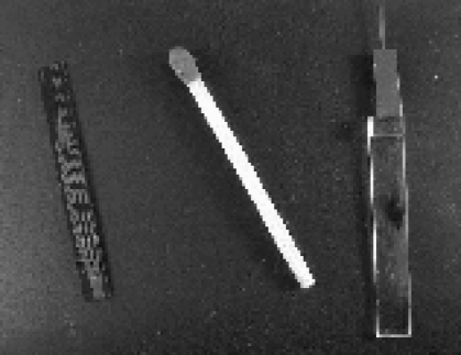
We have shown the great interest of using integrated optics for astronomical interferometry. Figure 8 shows a three-way beam combiner with photometric calibrating channels made with the silicon etching technology (Severi et al. 1999).
We argue that integrated optics technology which is already industrially mature, presents the following main advantages for astronomical interferometry:
-
•
Small size. A complete instrument can be integrated on a chip typically .
-
•
Stability. The instrument is completely stable while embedded in a substrate.
-
•
Low sensitivity to external constraints: temperature, pressure, mechanical constrains.
-
•
Few opto-mechanical mounts and little alignment required. The only concern is coupling light into the waveguides.
-
•
Simplicity. For a complex instrument, the major efforts are shifted to the design of the mask, not in the construction phase.
-
•
Intrinsic polarization capabilities (Sect. 5.3).
-
•
Low cost. Integrated optics provides very low cost components and instrumentation set-up. Furthermore the price is the same for one or several components since the main cost is in the design and initial realization of the mask.
6.2 Application to interferometry
Integrated optics components are not well-suited for wide wavelength coverage, high spectral dispersion and large field of view. Therefore, we do not think that it will completely replace existing techniques in astronomical interferometry. However with the characteristics presented in this article, we think that integrated optics will be attractive for the two following applications:
-
•
Interferometers with a large number of apertures.
Whatever the complexity of the instrumental concept, only one component in integrated optics allows combination of several beams and ensures the photometric calibrations at low cost and with limited alignments -
•
Space-based interferometers.
Integrated optics components with no internal alignments provide reliable beam combiners for spatial interferometry.
These specific advantages lead us to perform laboratory experiments to validate this approach. An interferometric workbench has been built to completely characterize various components realized by both technologies. First fringes with a white source have been obtained (Berger et al. 1999, , paper II) and the integration of an interferometric instrument dedicated to astronomical observations in the H and K atmospheric bands is in progress (Berger et al. 1998).
7 Acknowledgments
The authors are grateful to F. Reynaud (IRCOM - Univ. Limoges), P. Pouteau, P. Mottier and M. Séveri (CEA/LETI - Grenoble) for fruitful discussions, and to E. Le Coarer and P. Feautrier for the idea of combining integrated optics and STJ. We would like to thank K. Wallace for carefully reading the manuscript. The works have partially been funded by PNHRA/INSU, CNRS/Ultimatech and DGA/DRET (Contract 971091).
References
- Alferness (1982) Alferness R.C. 1982, IEEE Transactions on Microwave Theory Techniques, 30, 1121
- Baldwin et al. (1996) Baldwin J.E., et al. 1996, A&A 306, L13
- Benson et al. (1997) Benson J.A., et al. 1997, AJ 114, 1221
- Berger et al. (1998) Berger J.-P., Rousselet-Perraut K., Kern P., Malbet F., Schanen-Duport I., Nabias L., Benech P. 1998, Integrated Optics components for interferometric beam combination. In: Reasenberg R.D. (ed.) Proc. SPIE 3350, Astronomical Interferometry, p. 898.
- Berger et al. (1999) Berger J.-P., Rousselet-Perraut K., Kern P., Malbet F., Schanen-Duport I., Reynaud F., Haguenauer P., Benech P. 1999, A&A, in press (paper II).
- Carleton et al. (1994) Carleton N. P., et al. 1994, Current status of the IOTA interferometer. In: Breckinridge J.B. (ed.) Proc. SPIE 2200, Amplitude and Intensity Spatial Interferometry II, 152.
- Colavita et al. (1991) Colavita M.M., Hines B.E., Shao M. Klose G.J., Gibson B.V. 1991, Prototype high speed optical delay line for stellar interferometry. In: Ealey M.A. (ed.) Proc. SPIE 1542, Active and Adaptive Optical Systems, 205
- Colavita et al. (1994) Colavita M.M., et al. 1994, ASEPS-0 testbed interferometer. In: Breckinridge J.B. (ed.) Proc. SPIE 2220, Amplitude and Intensity Spatial Interferometry II, 89
- Colavita et al. (1998) Colavita M.M., et al. 1998, Keck Interferometer. In: Reasenberg R.D., Unwin S.C. (eds.) Proc. SPIE 3350, Astronomical Telescopes and Instrumentation: Astronomical Interferometry, in press
- Connes et al. (1984) Connes P., Froehly C., Facq P. 1984, A Fiber-Linked Version of Project TRIO. In: Longdon N., Melita O. (eds.) Proc. ESA Colloq., Kilometric Optical Arrays in Space. ESA, Cargèse, p. 49
- Coudé du Foresto (1996) Coudé du Foresto V. 1996, Fringe Benefits: the Spatial Filtering Advantages of Single-Mode Fibers. In: Kern P., Malbet F. (eds) Proc. AstroFib’96, Integrated Optics for Astronomical Interferometry. Bastianelli-Guirimand, Grenoble, p. 27
- Coudé du Foresto & Ridgway (1991) Coudé du Foresto V., Ridgway S. 1991, FLUOR: a Stellar Interferometer Using Single-Mode Infrared Fibers. In: Beckers J., Merkle F. (eds.) Proc. ESO conf., High-resolution imaging by interferometry II. ESO, Garching, 731
- Coudé du Foresto et al. (1996) Coudé du Foresto V., Perrin G., Mariotti J.-M., Lacasse M., Traub W. 1996, The FLUOR/IOTA Fiber Stellar Interferometer. In: Kern P., Malbet F. (eds) Proc. AstroFib’96, Integrated Optics for Astronomical Interferometry. Bastianelli-Guirimand, Grenoble, p. 115
- Davis et al. (1994) Davis J., Tango W.J., Booth A.J., Minard R.A., Owens S.M., Shobbrook R.R. 1985, Progress in commissioning the Sydney University Stellar Interferometer (SUSI). In: Breckinridge J.B. (ed.) Proc. SPIE 2220, Amplitude and Intensity Spatial Interferometry II, 231
- Fizeau (1868) Fizeau H. 1868, C. R. Acad. Sci. Paris, 66, 932
- Froehly (1981) Froehly C. 1981, Coherence and Interferometry through Optical Fibers. In: Ulrich M.H., Kjär K. (eds.) Proc. ESO conf., Science Importance of High Angular Resolution at Infrared and Optical Wavelengths. ESO, Garching, p. 285
- Jeunhomme (1990) Jeunhomme L. 1990, Single-mode fiber optics, Marcel Dekker Inc.
- Kern et al. (1996) Kern P., Malbet F., Schanen-Duport I., Benech P. 1996, Integrated optics single-mode interferometric beam combiner for near infrared astronomy. In: Kern P., Malbet F. (eds) Proc. AstroFib’96, Integrated Optics for Astronomical Interferometry. Bastianelli-Guirimand, Grenoble, p. 195
- Feautrier et al. (1998) Feautrier P., et al. 1998, Superconducting Tunnel Junctions for photon counting in the near infrared wavelengths. In: Applied Superconductivity Conference, Palm Desert
- Koechlin et al. (1996) Koechlin L., et al. 1996, Appl. Opt. 35, 3002
- Labeyrie (1975) Labeyrie A. 1975, ApJ 196, L71-L75
- Lang (1997) Lang T. 1997, PhD Thesis, University of Grenoble, France.
- Lefèvre (1980) Lefèvre H.C. 1980, Electron. Letters 16,778
- Roddier & Léna (1984) Roddier F., Léna P. 1984, J. Opt. 15, 171
- Roddier & Léna (1984) Roddier F., Léna P. 1984, J. Opt. 15, 363
- Mariotti (1998) Mariotti J.-M. 1998, VLTI: a Status Report. In: Reasenberg R.D., Unwin S.C. (eds.) Proc. SPIE 3350, Astronomical Telescopes and Instrumentation: Astronomical Interferometry, in press
- Mariotti & Ridgway (1988) Mariotti J.-M., Ridgway S. 1988, A&A 195, 350
- Mariotti et al. (1992) Mariotti J.-M., et al. 1992, Coherent Combined Instrumentation for the VLT Interferometer. VLT Report No 65, ESO, Garching
- Mariotti et al. (1996) Mariotti J.-M., Coudé du Foresto V., Perrin G., Zhao P., Léna P. 1996, A&AS 116, 381
- McAlister et al. (1994) McAlister H.A., et al. 1994, CHARA Array. In: Breckinridge J.B. (ed.) Proc. SPIE 2200, Amplitude and Intensity Spatial Interferometry II, 129.
- Michelson & Pease (1921) Michelson A.A., Pease F.G. 1921, ApJ 53, 249
- Miller (1969) Miller S.E. 1969, The Bell System Technical Journal, vol. 48, 2059
- Mottier (1996) Mottier P. 1996, Integrated Optics and Micro-Optics at LETI. In: Kern P., Malbet F. (eds) Proc. AstroFib’96, Integrated Optics for Astronomical Interferometry. Bastianelli-Guirimand, Grenoble, p. 63
- Mourard et al. (1994) Mourard D., Tallon-Bosc I., Blazit A., Bonneau D., Merlin G., Morand F., Vakili F., Labeyrie A. 1994, A&A 283, 705
- Ollier & Mottier (1996) Ollier E. & Mottier P. 1996, Electronics Letters, Vol. 32, 21
- Petrov et al. (1998) Petrov R.G., Malbet F., Richichi A., Hofmann K.-H. 1998, The ESO Messenger, 92, 11
- Rabbia et al. (1996) Rabbia Y., Ménardi S., Reynaud F., Delage L. 1996, The ESO-VLTI fringe sensor. In: Kern P., Malbet F. (eds) Proc. AstroFib’96, Integrated Optics for Astronomical Interferometry. Bastianelli-Guirimand, Grenoble, p. 175
- Ramaswamy & Srivastava (1988) Ramaswamy R.V., Srivastava R. 1988, J. of Light. Tech. 6, 984
- Reynaud (1993) Reynaud F. 1993, Pure Applied Optics 2, 185-188.
- Reynaud & Delaire (1994) Reynaud F., Delaire E. 1994, Linear Optical Path Modulation with a Lambda/200 Accuracy Using a Fiber Stretcher. In: Cerutti-Maori M.-G., Roussel Ph. (eds.), Proc. SPIE 2209, Space Optics 1994: Earth Observation and Astronomy, 431
- Reynaud & Lagorceix (1996) Reynaud F, Lagorceix H. 1996, Stabilization and Control of a Fiber Array for the Coherent Transport of Beams in a Stellar Interferometer. In: Kern P., Malbet F. (eds) Proc. AstroFib’96, Integrated Optics for Astronomical Interferometry. Bastianelli-Guirimand, Grenoble, p. 249
- Reynaud et al. (1994) Reynaud F, Alleman J.J., Lagorceix H. 1994, Interferometric fiber arms for stellar interferometry. In: Cerutti-Maori M.-G., Roussel Ph. (eds.), Proc. SPIE 2209, Space Optics 1994: Earth Observation and Astronomy, 431
- Richier (1996) Richier R. 1996, End-Coating in Optical Fibers Developments and Application. In: Kern P., Malbet F. (eds) Proc. AstroFib’96, Integrated Optics for Astronomical Interferometry. Bastianelli-Guirimand, Grenoble, p. 163
- Ross (1989) Ross L. 1989, Glastechniche Berichte 62, 285
- Rousselet-Perraut et al. (1996) Rousselet-Perraut K., Vakili F., Mourard D. 1996, Optical Engineering Vol. 35, 10, 2943
- Rousselet-Perraut et al. (1998) Rousselet-Perraut K.,Hill L., Lasselin-Waultier G., Boit J.L., Rousset G., Blanc J.C. and Voet C. 1998, Optical Engineering Vol. 37, 2, 610
- Schanen-Duport et al. (1996) Schanen-Duport I., Benech P., Kern P., Malbet F. 1996, Optical Waveguides Made by Ion Exchange for Astronomical Interferometry Applications at the Wavelength of 2.2 Microns. In: Kern P., Malbet F. (eds) Proc. AstroFib’96, Integrated Optics for Astronomical Interferometry. Bastianelli-Guirimand, Grenoble, p. 99
- Schanen-Duport et al. (1998) Schanen-Duport I., El-Sabban S., Berger J.P., Kern P., Malbet F., Rousselet- Perraut K. 1998, Proc. JNOG, Marly-le-Roi.
- Severi et al. (1999) Severi M., Pouteau P., Mottier P., Kern P. 1999, A waveguide interferometer for phase closure in astronomy. In: ECIO’99, Torino, 15 April 1999.
- Shaklan (1990) Shaklan S.B. 1990, Optical Engineering 29, 684
- Shaklan & Roddier (1987) Shaklan S.B., Roddier F. 1987, Applied Optics 26, 2159
- Shaklan & Roddier (1988) Shaklan S.B., Roddier F. 1988, Applied Optics 27, 2334
- Shao & Staelin (1977) Shao M., Staelin D.H. 1977, JOSA 67, 81
- Shao et al. (1988) Shao M., Colavita M.M., Hines B.E., Staelin D.H., Hutter D.J. 1988, A&A 193, 357
- Simohamed & Reynaud (1996) Simohamed L.M., Reynaud F. 1996, A Two Meter Stroke Optical Fibre Delay Line. In: Kern P., Malbet F. (eds) Proc. AstroFib’96, Integrated Optics for Astronomical Interferometry. Bastianelli-Guirimand, Grenoble, p. 217
- Stefan (1874) Stéphan E. 1874, C. R. Acad. Sci. Paris, 78, 1008
- Strohhöfer et al. (1998) Strohhöfer et al. 1998, Active optical properties of Erbium-doped Ge-based sol-gel planar waveguides, In: Thin Solid Films, in press
- Turner & Brummelaar (1997) Turner N.H., Brummelaar T. 1997, BAAS 190
- White et al. (1994) White N.M., et al. 1994, Progress Report on the Construction of the Navy Prototype Optical Interferometer at the Lowell Observatory. In: Breckinridge J.B. (ed.) Proc. SPIE 2220, Amplitude and Intensity Spatial Interferometry II, 242.
- Zernike & Midwinter (1973) Zernike F., Midwinter J.E. 1973, Applied nonlinear optics, Wiley sons
- Zhao et al. (1995) Zhao P., Mariotti J.-M., Coudé du Foresto V., Léna P., Perrin G. 1995, Multistage Fiber Optic Delay Line for Astronomical Interferometry. In: Barden S.C. (ed.), proc. SPIE 2476, Fiber Optics in Astronomical Applications, 108