CBR Polarization Experiments
Abstract
A handful of new experiments aimed at measuring the as-yet-undetected polarization of the cosmic background radiation (CBR) are described, with somewhat more detail given for three experiments with which the authors are associated.
keywords:
cosmic background, cosmic microwave background, polarization1 Introduction
Since Penzias & Wilson published their groundbreaking report of the existence of the CBR (1965), experimentalists have been checking to see if the CBR is polarized. CBR polarization experiments are challenging. Predicted polarization signals are an order of magnitude below the levels at which CBR anisotropy experiments have only just begun to detect signals. Typical polarization signals are a few K. The most significant challenges include achieving adequate statistical sensitivity, limiting systematic errors sufficiently to detect the small polarization signal, and discriminating the CBR polarization from foreground sources such as galactic synchrotron radiation. To date, no polarization has been detected, but several experiments which have just begun operation or plan to within the year are designed to reach the sensitivities required to detect polarized signals of about the size predicted by CDM models. Figure 1 shows the angular resolution and frequency coverage of the new and recent experiments. Some details about the experiments are listed in Table 1.
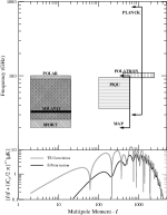
After a brief inspection of Figure 1, one sees that the experimentalist is faced with a difficult choice. Should s/he design an experiment to search for a CBR polarization signal at large angles, where the spectrum codes information about reionization and the existence of tensor fluctuations? Such an experiment has the potential of enormous scientific payback if the CBR exhibits the coherent oscillation anisotropy spectrum predicted by models with adiabatic initial fluctuations amplified by a period of inflation. Also, a horn antenna can be used to attain beamwidths of a few degrees, without the need for reflectors which might introduce certain systematic errors. However, the aforementioned models predict that the CBR polarization anisotropy will be very small, less than K, at angular scales larger than a couple of degrees. Extant limits at those angular scales are more than three orders of magnitude greater than the expected signal. The other choice for the experimentalist is to design an experiment to probe the polarization anisotropy at smaller angular scales, where the predicted signal from standard CDM is larger. These experiments must contend with polarized offsets due to the use of reflectors (or lenses).
At present, groups are pursuing both lines of attack, as indicated in Figure 1. The space-based MAP and Planck satellites plan to collect data from large fractions of the sky with small resolutions, which allows probing of small and large angular scales at once. Ground-based experiments complement the satellite missions because of their ability to probe specific regions of sky more deeply. MAP, for example, is expected to only make a statistical detection of the polarization anisotropy, while ground-based experiments should be able to detect polarization directly. Also, since no detections of polarization have yet been claimed, experimenters and analysts may not yet have beaten down all the relevant systematic errors which will plague the measurements; the ground-based experiments will address systematic effects as they become evident. Experience on the ground may prove helpful to the satellite experiments. A further distinction is that the current crop of ground-based experiments compare the orthogonal linear polarization components within a single beam at a time rather than comparing them between beams separated on the sky.
2 Overview of Techniques
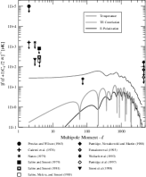
Figure 2 presents current experimental limits on the CBR polarization. The first experiments dedicated toward detecting or limiting the CBR polarization (Caderni et al. 1978; Nanos 1979; Lubin & Smoot 1979, 1981; Lubin, Melese & Smoot 1983) modulated the polarization of the incoming signal (either with a Faraday switch or a mechanical rotating analyzer) and locked in at the modulation frequency to measure or , depending on the orientation of the polarimeter. The increased sensitivity of bolometer-based and HEMT111HEMT stands for high electron mobility transistor; amplifiers using HEMTs have very low noise (Pospieszalski 1992, 1995).-amplifier-based radiometers being built today is such that the systematic effects associated with the Faraday switch may be too large to tolerate. (Faraday switches are very sensitive to temperature variations and external magnetic field variations.) The modulation frequency of a mechanically rotating analyzer is limited in practice. Several new methods of Dicke-switching are described below.
One other experimental limit appears in Figure 2, the limit from the Saskatoon anisotropy experiment (Wollack et al. 1993), at . This experiment collected temperature differences between patches on the sky, . Measurements of were made in two orthogonal linear polarizations, so that the polarization anisotropy limit comes from comparing the two sets of . Thus, the variance of the polarization anisotropy measured includes a component due to the spatial variation of the (unpolarized) atmosphere. In other words, the best limit on the plot comes from an experiment optimized to measure the temperature anisotropy, not the polarization!222In fact, later data from Saskatoon at a slightly larger give an even lower limit to the polarization, but the full analysis has not yet been completed. (Page 1999). The current crop of polarization experiments (with the exception of some satellite missions which do not have to contend with atmospheric spatial variations) measure the difference between two orthogonal linear polarizations within a single beam at a time.
Receivers used in the current experiments dedicated to polarimetery of the CBR may be divided into two categories: 1) bolometer pairs read out in an AC bridge, such as the bolometer-bridge polarimeter invented for use in the Polatron experiment described below and 2) HEMT-amplifier correlation receivers. Correlation receivers (Fujimoto, 1964; Rohlfs & Wilson, 1996) comprise two types also: a) receivers in which the two signals proportional to the electric fields from the two orthogonal polarizations are multiplied together directly in a nonlinear device and b) receivers in which the two signals are split and recombined with appropriate phase shifts into four signals which are subsequently detected and differenced to give and . The former type of correlation receiver is typically less bulky and capable of larger bandwidths than the latter, but requires care to ensure sufficient dynamic range. All these receivers may be Dicke-switched rapidly. In particular, the correlation receivers may be phase-switched at several kilohertz, fast enough to overcome the knee of even the highest frequency (90 GHz) HEMT amplifiers. The switching is achieved by inserting a relative phase shift of or between the two incoming signals; the output of a correlation receiver is proportional to , where is the total phase shift between the two incoming signals. Direct-multiplication correlators are used in the POLAR and PIQU experiments, while the Milano polarimeter and the SPOrt experiment use detect-and-difference correlation schemes. (Peter Timbie pioneered the use of direct-multiplication correlation receivers for CBR anisotropy in the 1980’s: reference Timbie.)
3 Polarization Experiments at the Turn of the Millenium
Due to the authors’ familiarity with three of the current ground-based polarization experiments, we devote unequal attention to those in what follows. For completeness, we mention five other experiments of which we are aware. The frequency coverage and coverage of these experiments is depicted in Figure 1. Much of the other pertinent information is condensed in Table 1. First we discuss ground-based experiments, beginning with the experiment sensitive to the smallest angular scales. Then we discuss space-based experiments briefly.
3.1 The VLA 8.4 GHz CBR Project.
Partridge et al. (1997) recently completed imaging and analysis of a 40 arcmin2 field at 8.44 GHz with 6\arcsecresolution, using the VLA. The signals were collected in circular polarization, and all four Stokes parameters recovered. The data came from 159 hours of observations; such a project is unlikely to be repeated. This work follows up on earlier work at lower resolution (Fomalont et al. 1993) and at lower frequency (Partridge et al. 1988). These three papers contain the only published CBR polarization limits from interferometry to date; the results are summarized in Figure 2.
3.2 The Polatron.
The Polatron experiment is being built by a team comprising members from Caltech, Stanford University and Queen Mary and Westfield College. The Polatron will be used to search for CBR polarization on arcminute angular scales where the amplitude of the polarization power spectrum is expected to peak. Observations will be made at a frequency of 100 GHz where confusion from polarized foregrounds is expected to be a minimum.
The corrugated entrance feed of the Polatron will be located at the Cassegrain focus of the 5.5 m dish at the Owens Valley Radio Observatory (OVRO), generating a beam on the sky. A broad-band OMT (orthomode transducer, see Chattopadhyay et al. 1999) splits the incoming signal into two orthogonal linear polarizations. The backend of the polarimeter feeds two bolometers, each of which detects one of the linear polarization states that comes from the OMT. Metal-mesh resonant filters located between the OMT and the bolometers define a 20% passband centered at 96 GHz. An AC-bridge readout circuit (see, for example, Holzapfel et al. 1997) will be used to difference the outputs from the two bolometers. At any instance, this differencing scheme permits the measurement of a single Stokes parameter (Q or U). By rotating the plane of polarization by 45∘ with a quartz half-wave plate located in front of the entrance feed, a second Stokes parameter (U or Q) is then measured.
The silicon nitride metal-mesh bolometers (Bock et al. 1996) that will be used in the Polatron are identical to those that will be flown as part of the Planck Surveyor High Frequency Instrument (HFI) in 2006. The bolometers will be operated at 250 mK where they will have NEPs significantly lower than the background photon noise limit. In 1 second of integration on a single pixel, the Polatron is expected to measure each Stokes parameter to a precision of 700 K.
The Polatron will be commissioned in the summer of 1999 and will make its first observations in the winter of 1999/2000. In 6 months it is expected that the Polatron will observe 850 pixels to a sensitivity of 8 K per pixel in each of Q and U. In a standard CDM model, this will be sufficient to detect rms polarization at 5. Over its projected four-year lifetime, the Polatron plans to map out the polarization anisotropy between and .
3.3 The PIQU Experiment.
A group at Princeton University has designed an experiment nicknamed PIQU, for Princeton IQU, a reference to the Stokes parameters the experiment eventually plans to measure. PIQU will measure the polarization at small angular scales at two frequencies, 40 GHz and 90 GHz, with multiple horns in the focal plane. The experiment uses a 1.4 m off-axis parabola fed with a corrugated horn antenna to provide a beamwidth of for the 90 GHz radiometer. The RF signals from the two arms of an OMT, corresponding to two linear orthogonal polarizations from the sky, are mixed down to a 2–18 GHz IF, split into three sub-bands, and then directly multiplied together in a broad bandwidth mixer. The front end of the instrument uses HEMT amplifiers cooled to about 12 K. Phase-switching at 4 kHz is done in one LO line. Phase tuners in the IF lines and the LO line allow balancing of the phase to , such that the bandwidth degradation is less than 10%.
The phase-one instrument, PIQ-90, measures only one of and , chosen to be the polarization with the most symmetry with respect to the experimental apparatus, in an effort to minimize systematic effects. This instrument operates at 90 GHz and will be deployed to the roof of Princeton in the spring of 1999. A separate 40 GHz cryostat is being developed and will be operated in a follow-up data run subsequently. The 40 GHz receiver shares the IF components of the 90 GHz receiver. In subsequent years, multiple horns will be placed in the focal plane, using a larger cryostat, so that multiple multifrequency measurements may be made simultaneously.
3.4 The POLAR Experiment.
The Polarizaton Observations of Large Angular Regions (POLAR) experiment has been designed and built by the Observational Cosmology Group at the University of Wisconsin–Madison. POLAR is designed to measure the CBR’s and Stokes parameters in several broad bands between 26 and 100 GHz. POLAR observes the CBR polarization at large ( FWHM) angular scales–comparable to the COBE satellite. At these angular scales the rms CBR polarization signal is expected to be quite small (K) unless the Universe was reionized at an early epoch corresponding to a . The raw system noise of POLAR is a factor of 100 smaller than the instrument that was used to set the current upper limits on large angular scales (Lubin, Melese & Smoot, 1983). The primary goal of POLAR is to reach a sensitivity level of TT. At this level, POLAR will either detect polarization in the CBR or place a tight constraint on the epoch of reionization.
POLAR employs a correlation radiometer that uses a corrugated feed horn to couple the CBR into an orthomode transducer which decomposes the incoming radiation into two linear polarizations. These two linear polarized components are amplified using two HEMT amplifiers cooled to 15 K in a cryocooler. After an additional stage of ambient temperature amplification, the two parallel signal chains are mixed down to an intermediate frequency band (2-12 GHz) where they are multiplied. The IF is subdivided into three equal bands for additional foreground discrimination. The output of the correlator is proportional to where is the orientation of the polarimeter. POLAR began observations in the Ka-band (26-36 GHz) in September 1998 at the University of Wisconsin’s Pine Bluff Observatory. POLAR observes spots directly overhead in a strip at a declination of . Later in 1999, POLAR will add either a W-band (90-100 GHz) or Q-band (35-45 GHz) polarimeter (in the same cryostat) which will observe simultaneously with the Ka-band system. This additional polarimeter will help significantly in discriminating against foreground contamination. For additional information regarding POLAR, see Keating et al. 1998 and http://cmb.physics.wisc.edu/polar/. Future plans for the POLAR team include collaborating with UC-Santa Barbara to develop a small angular scale () polarimeter.
3.5 The Milano Polarimetry Project.
Sironi et al. (1998) have built and operated a 33 GHz polarimeter coupled to a corrugated feed horn. The correlation receiver uses a phase discriminator comprising several hybrid tees (which output an incoming signal on two ports which have a phase difference between them) and one hybrid tee. Both and are observed simultaneously. An extension to the feed horn allows data to be taken at ; data have also been collected in this mode (Sironi 1999). Future plans include mounting the polarimeter at the Cassegrain focus of the 2.6 m dish at Testa Grigia (Sironi et al. 1998), which would allow measurements with a beam.
3.6 Space-based Experiments.
The MAP and Planck Surveyor satellites are designed to measure the CBR temperature anisotropy across the entire sky. Both will also measure polarization. MAP, which is set to launch in fall of 2000, should make a statistical detection of polarization anisotropy. Planck, with proposed launch date of 2007, will be sensitive enough to detect polarization directly for most CDM models. SPOrt is an experiment dedicated to measuring CBR polarization. SPOrt is meant to be deployed on the International Space Station in 2001 or 2002.
The MAP satellite (Jarosik et al. 1998) will use polarization-sensitive radiometers to observe the whole sky, with a frequency-dependent resolution ranging from to . Data will be collected in five bands, from 22 GHz to 90 GHz. The receivers are phase-switched at 2.5 kHz, and use HEMT amplifiers. Corrugated feed horns couple to OMTs to separate two orthogonal linear polarizations. The primary reflectors are back to back dishes. The difference data consist of and where and designate the two orthogonal linear polarizations from horn A, and similarly for and . From such pairs of numbers one can derive a full-sky map of the polarization of the sky (Wright, Hinshaw, & Bennett 1995). Most of the radiometers are completely constructed and tested. More information is available at http://map.gsfc.nasa.gov/html/technical_info.html.
The Planck satellite (Tauber 1998) has two sets of receivers, the LFI set and the HFI set, for “Low-Frequency Instrument” and “High-Frequency Instrument.” The HEMT-based LFI radiometers are all linearly polarized, and include four bands between 30 and 100 GHz. The angular resolution for the LFI ranges from to . The HFI receivers use bolometers. Three of the six HFI frequency bands are linearly polarized (143 GHz, 217 GHz and 545 GHz). The resolution for polarized bands ranges from to . More information is available at http://astro.estec.esa.nl/SA-general/Projects/Planck/.
The SPOrt project (Cortiglioni, et al. 1998) aims to measure the polarization of over 80% of the sky in patches in several frequency bands between 20 and 90 GHz. The receivers are correlation receivers of the detect-and-difference variety, using phase-switching, and measuring and simultaneously.
4 Summary and Discussion
In addition to the CBR brightness spectrum and the temperature anisotropy, the CBR polarization represents the third treasure trove of information encoded in the CBR. The small polarization signal raises large barriers that undermine the ability to extract this information. These barriers include obtaining the requisite statistical sensitivity, minimizing systematic errors, and discriminating against foreground contamination. (See Tegmark, these proceedings.)
The experiments described above overcome these barriers in a variety of different ways. Long integration times (roughly 10 hours/pixel/detector) with ever more sensitive detectors will yield the statistical sensitivity needed to detect CBR polarization. These experiments will have to minimize systematic effects at levels that have yet to be charted. The minimization of these systematic effects impacts the design and implementation of experiments in many different ways as demonstrated by the variety of experiments described above. The foregrounds that could contaminate CBR polarization are not well characterized. Polarized galactic synchrotron radiation is the only known foreground, and its intensity (much less its polarization) has yet to be measured at high galactic latitudes at the relevant frequencies. The best way to marginalize this ignorance is to perform multifrequency measurements, as temperature anisotropy experiments have shown. Since the best overall approach has yet to be determined, the community will invariably benefit from the variety of experimental approaches described above.
| Experiment | beamsize\tablenotemarka | frequency | Receiver\tablenotemarkb | Site |
|---|---|---|---|---|
| GHz | ||||
| \tablelineVLA | 8.44 | int | NM desert | |
| POLATRON | 96 | bolo br | OVRO | |
| PLANCK HFI | 143, 217, 545 | bolo | space L2 | |
| PIQU | 40, 92 | HCdm | Princeton, NJ | |
| PIQU2\tablenotemarkc | 40, 92 | HCdm | high alt site | |
| MAP | 22, 33, 40, 61, 98 | HTP | space L2 | |
| PLANCK LFI | 30,44,70,100 | HTP | space L2 | |
| POLAR | 30 & 40 or 90 | HCdm | Madison, WI | |
| SBUW\tablenotemarkc | 30 & 40 or 90 | HCdm | high alt US | |
| SPORT | 22, 32, 60, 90 | HCdd | space station | |
| Milano | 33 | HCdd | Antarctica | |
| Milano2\tablenotemarkc | 33 | HCdd | Alps |
aThe smallest beamsize is given; most of the experiments have frequency-dependent beamsizes. \tablenotetextbReceiver types include int (inteferometer), bolo br (bolometers in AC bridge), bolo (bolometers), HCdm (HEMT correlation receivers with direct multiplication), HCdd (HEMT correlation receivers using recombination of signals with appropriate phases, followed by detection and differencing), and HTP (HEMT total power – see text and the MAP website for more information.) \tablenotetextc These three experiments are planned upgrades to existing experiments; the exact parameters are not yet determined. SBUW is a collaboration between UC–Santa Barbara and the existing POLAR team.
References
- [1]
- [2] ock J.J., DelCastillo H.M., Turner A.D., Beeman J.W., Lange A.E. & Mauskopf P.D., 1996, in proceedings of the 30th ESLAB Symposium: ‘Submillimetre and Far- Infrared Space Instrumentation’, SP-388, 119.
- [3]
- [4] aderni, N. 1978, Phys. Rev. D, 17, 1908.
- [5]
- [6] hattopadhyay G., Philhour B., Carlstrom J., Church S., Lange A. & Zmudzinas J., 1999, IEEE microwave and guided wave letters, submitted.
- [7]
- [8] ortiglioni, S. Cecchini, S., Carretti, E., Orsini, M., Fabbri, R., Boella, G., Sironi, G., Monari, J., Orfei, A., Tascone, R., Pisani, U., Ng, K. W., Nicastro, L., Popa, L., Strukov, I. A., & Sazhin, M. V. 1998, astro-ph/9901362.
- [9]
- [10] omalont, E. B., Partridge, R. B. Lowenthal, J. D. & Windhorst, R. A. 1993, ApJ, 404, 8.
- [11]
- [12] ujimoto, K. 1964, IEEE-MTT, 203.
- [13]
- [14] olzapfel W.L., Wilbanks T.M, Ade P.A.R., Church S.E., Fischer M.L., Mauskopf P.D., Osgood D.E. & Lange A.E., 1997, ApJ, 479, 17.
- [15]
- [16] arosik, N., Limon, M., Page, L., Spergel, D., Wilkinson, D., Bennett, C., Hinshaw, G., Kogut, A., Mather, J., Halpern, M., Meyer, S., Tucker, G., Wollack, E., & Wright, E. 1998, Proceedings of the XXXIIIrd Rencontres de Moriond, Editions Frontiers, Paris, 249.
- [17]
- [18] eating, B., Timbie, P., Polnarev, A., & Steinberger, J. 1998, ApJ, 495, 580.
- [19]
- [20] ubin, P. M., & Smoot, G. F. 1981, ApJ, 245, 1.
- [21]
- [22] ubin, P. M., & Smoot, G. F. 1979, Phys. Rev. Lett., 42, 2, 129.
- [23]
- [24] ubin, P., Melese, P. & Smoot, G. 1983, ApJ, 273, L51.
- [25]
- [26] anos, G. 1979, ApJ, 232, 341.
- [27]
- [28] etterfield, C. B., Jarosik, N., Page, L., Wilkinson, D., & Wollack, E. 1995, ApJ, 445, L69.
- [29]
- [30] age, L. A. 1999, private communication.
- [31]
- [32] artridge, R. B., Nawakowski, J., & Martin, H. M. 1988, Nature, 311, 146.
- [33]
- [34] artridge, R. B., Richards, E. A., Fomalont, E. B., Kellerman, K. I., & Windhorst, R. A. 1997, ApJ, 483, 38.
- [35]
- [36] enzias, A. & Wilson, R. 1965, ApJ, 142, 419.
- [37]
- [38] ospieszalski, M. 1992, IEEE-MTT-S Digest, 1369.
- [39]
- [40] ospieszalski, M. 1995, IEEE-MTT-S Digest, 1121.
- [41]
- [42] ohlfs, K. & Wilson, T. L. 1996, Tools of Radio Astronomy, Springer-Verlag, Berlin.
- [43]
- [44] eljak, Uroš, & Zaldarriaga, Matias 1996, ApJ, 469, 437.
- [45]
- [46] ironi, G., Boella, G. Bonelli, G., Brunetti, L., Cavaliere, F., Fervasi, M., Giardino, G., & Passerini, A. 1998, New Astronomy, 3, 1.
- [47]
- [48] ironi, G. 1999, private communication.
- [49]
- [50] auber, J. A., 1998, Proceedings of the XXXIIIrd Rencontres de Moriond, Editions Frontiers, Paris, 255.
- [51]
- [52] ollack, E. J., Jarosik, N. C., Netterfield, C. B., Page, L. A., & Wilkinson, D. 1993, ApJ, 419, L49.
- [53] right, E. L., Hinshaw, G., & Bennett, C. L. 1995, ApJ, 458, L53.
- [54]
- [55] aldarriaga, M., & Seljak, U. 1997, Phys. Rev. D, 55, 1830.
- [56]