New methods for masked-aperture and speckle interferometry
Abstract
Diffraction-limited images can be obtained with a large optical telescope using interferometry. One such method for objects of sufficient brightness is non-redundant masking (NRM), in which observations are made through a pupil mask that contains an array of small holes. However, NRM only uses a small fraction of the available light. Here I describe a method for Extended NRM in which a cylindrical lens allows interferograms from many one-dimensional arrays to be recorded side-by-side on a two-dimensional detector.
For fainter objects, the holes in the aperture mask should be replaced by slits. In this case, the mask can be removed entirely, with the cylindrical lens effectively creating a continuous series of one-dimensional interferograms. This modified form of speckle interferometry, which I call MODS (Multiplexed One-Dimensional Speckle), is intermediate between NRM and conventional full-aperture speckle. An existing speckle camera can easily be converted to MODS observations by inserting a cylindrical lens. The feasibility of both MODS and Extended NRM are demonstrated using observations with MAPPIT at the Anglo-Australian Telescope.
1 Introduction
There are two approaches to achieving high angular resolution with a large ground-based telescope. Both involve compensating for distortions in the wavefront of the light that result from its passage through the atmosphere. The first approach is to make these corrections in real time using an adaptive optics system, which employs a deformable mirror whose shape is controlled by a large number of actuators (see ? (? ? (? for a review). However, although adaptive optics shows great promise for infrared imaging, its application to visible wavelengths poses formidable problems because of the very large number of actuators required.
The passive approach to high-resolution imaging relies on interferometry and involves recording many short-exposure images, each of which ‘freezes’ the atmospheric turbulence. These images are processed off-line by calculating the power spectrum and bispectrum, which yield the visibilities and closure phases of the object. This technique is known as speckle imaging Lab78; Wei91; NegReg96 and can be used to reconstruct a diffraction-limited image.
A variation on this passive approach is non-redundant masking (NRM), in which the short-exposure images are taken through a pupil mask that contains a small number of holes, arranged so that all the baseline vectors are distinct HMT87; NKG89. Masking the telescope pupil in this way, although only feasible for bright objects, has several advantages (? (? ? (?; see also ? (? ? (?). These include: (i) an improvement in signal-to-noise ratios for the individual visibility and closure phase measurements; (ii) attainment of the maximum possible angular resolution by giving full weight to the longest baselines; and (iii) a resistance to variations in atmospheric conditions and a consequent improvement in the accuracy of visibility calibration. The spatial-frequency plane is coarsely sampled relative to observations with a fully-filled aperture, but each measurement is more accurate.
NRM has been successfully used to image close binaries and to measure angular diameters of cool stars HMT87; NKG89; BRM94b; HST95; BZvdL97. Most importantly, it has revealed the presence of hotspots and other asymmetries on the surface of red supergiants and Mira variables BHB90; WBB92; HGG92; THB97; BZvdL97.
2 Extended NRM
Two disadvantages of NRM stem from its use of only a small fraction of the telescope pupil: (i) the instantaneous coverage of spatial frequencies is sparse; and (ii) most of the available light is discarded. The first point can be mitigated by combining observations made with different masks and/or with the masks rotated to several different position angles on the sky. The second is more serious and is presumably responsible for a reluctance in the wider community to make use of aperture masks. Interestingly, similar considerations have not prevented the use of detectors with low duty cycles, such as intensified CCDs that are only capable of recording a few frames per second WBH96; KEM97. In contrast, NRM experiments have been able to take advantage of fast one-dimensional detectors with 100% duty cycle, in the form of CCDs with on-chip binning BHB90.
In any case, it would clearly be desirable to devise a scheme which makes use of the whole pupil while maintaining the advantages of NRM. ? (?) discusses methods for so-called Extended NRM, in which the pupil is divided into many slices that are treated separately. One version requires an instrument with a series of masks, each transmitting a fraction of the light to a detector and reflecting the remainder to subsequent masks. An alternative method is to image the pupil onto a bundle of optical fibres, which are again divided among several detectors.
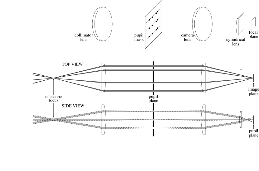
A much simpler approach, mentioned briefly by ? (?), is to use a cylindrical lens. A method for this is shown schematically in Figure 1. The mask, which contains several parallel linear arrays of holes, is placed in a collimated beam. The optics in the interference direction (top view) form a conventional image-plane interferometer, with the camera lens producing an image of the star crossed by interference fringes. In the orthogonal direction (side view), the cylindrical lens produces a pupil image, which ensures that the beams from the different hole arrays are spatially separated in the focal plane. For simplicity, Figure 1 shows a mask with three identical four-hole arrays. In practice, more than three arrays would be used and they could all be different. Also required, but not shown in the diagram, are a narrow-band filter and a two-dimensional detector. A microscope objective may also be necessary to ensure sufficient magnification.
Note that the arrangement proposed here is very similar to the wavelength-dispersed system developed by ? (?), but with the dispersing prism being replaced by a narrow-band filter and with a mask having several parallel arrays of holes. The second dimension of the detector is now used, not for wavelength information, but for recording many simultaneous sets of fringes.
2.1 Test observations of Extended NRM
A test of this concept was made at the coudé focus of the 3.9-metre Anglo-Australian Telescope (AAT) using the MAPPIT facility, which was developed for interferometry and NRM BRM94b. The components of MAPPIT are mounted on two optical rails attached to the telescope foundation, providing great freedom to experiment with different optical configurations. The tests were made on 1995 January 14 during periods of intermittent cloud which had interrupted the scheduled observing program. Despite the cloud, the seeing was quite good ( 1′′). The detector was a Thomson CCD with 19 µm pixels, although only a subset of the CCD was read out. The wavelength region was selected using an interference filter with central wavelength of 650 nm and a transmission bandwidth of 40 nm.
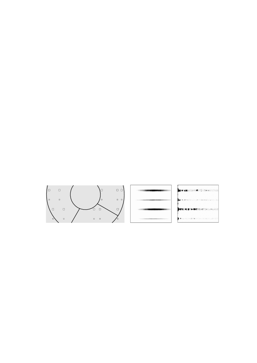
Figure 2 shows an observation of a bright star made with this system. The image (centre) is a single 2-second exposure and contains 225205 pixels. The horizontal scale is 0.016′′ per pixel, so the image width is 3.5′′ on the sky. In the vertical direction, which corresponds to an image of the masked pupil, one row on the CCD projects to 0.9 cm on the primary mirror. The diagram on the left shows the approximate position of the mask with respect to the AAT pupil. As can be seen, the mask holes are square and come in two sizes — these have projected diameters of 5 and 8 cm, respectively.
The right panel of Figure 2 shows the result of calculating the power spectrum of each row of the image. Zero spatial frequency is at the left, and each baseline sampled by the mask produces a spot. Despite the relatively long exposure (2 s), which was substantially longer than the atmospheric coherence time, power is detected on most baselines in this single exposure. In practice, one would use a large number of shorter exposures.
This preliminary test demonstrates the feasibility of Extended NRM. The mask was not designed for this application, and two of the holes actually fall outside the AAT pupil. An optimized system would use a mask with many more arrays, perhaps having different numbers of holes with various distributions and sizes. Extracting the object visibilities and closure phases, followed by model fitting or image reconstruction, would proceed as for conventional NRM.
The improvement over conventional NRM comes from the ability to make observations simultaneously with many parallel mask array. It should be possible to fit up to 20–30 different arrays on the pupil, which would reduce by this factor the total observing time required to acquire a given amount of data. However, this gain may be almost completely offset by the need to use a two-dimensional detector, since one would be forced to a lower duty cycle than is possible with a fully binned CCD, as are currently used for conventional NRM BHB90. A practical system based on Extended NRM should probably wait for a two-dimensional detector with high duty cycle.
3 Multiplexed one-dimensional speckle (MODS)
An obvious way to extend aperture masking to fainter objects is to replace the array of small holes by a thin slit. Indeed, a slit was suggested by ? (?) as a good compromise between standard speckle techniques and Michelson interferometry. ? (?) confirmed this by showing that the best signal-to-noise for individual visibility and closure phase measurements at low light levels is achieved with a pupil having a high degree of redundancy and a small surface area. This is because the signal on a given baseline (or closure-phase triangle) increases with the redundancy, while photon noise increases with the total area of the pupil (we are assuming that photon noise dominates any contribution from detector read noise). A slit, having high redundancy per unit area, is ideal. It largely retains two of the advantages of NRM mentioned in the Introduction (improved signal-to-noise and full resolution), although the accuracy of visibility calibration in the presence of variable seeing is not much better than for conventional full-aperture speckle.
The method described in Section 2 can easily be applied to a mask with slits. The cylindrical lens ensures that each slit is imaged separately on the detector. Furthermore, we can imagine adding more and more slits until they become so close together that they fill the whole pupil. At this point we can remove the mask entirely. Such an arrangement effectively has many adjacent pseudo-slits, and I will refer to it as Multiplexed One-Dimensional Speckle (MODS).
3.1 Test observations of MODS
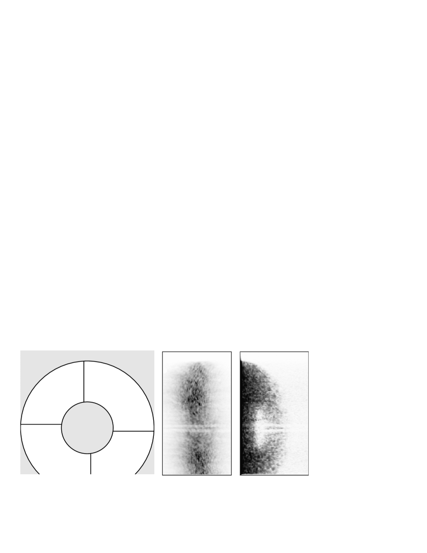
Observations using the MODS technique were made using the setup described above, but with the mask removed. Figure 3 presents observations of a bright star. The diagram on the left shows the AAT pupil, including the obstruction from the secondary mirror and the vanes that support it. The image (centre) is a single 0.2-second exposure and contains 225400 pixels. The horizontal and vertical scales are the same as in Figure 2. Speckle patterns and the shadows of the vanes are clearly visible, as are fine fringes due to interference across the central obstruction.
As before, we can process each row of the detector independently. The row-by-row power spectrum is shown in the right panel of Figure 3 and shows power out to the diffraction limit. The central obstruction of the AAT is more than one third of the telescope diameter, so the central part of the row-by-row power spectrum contains a gap in the coverage of spatial frequencies.
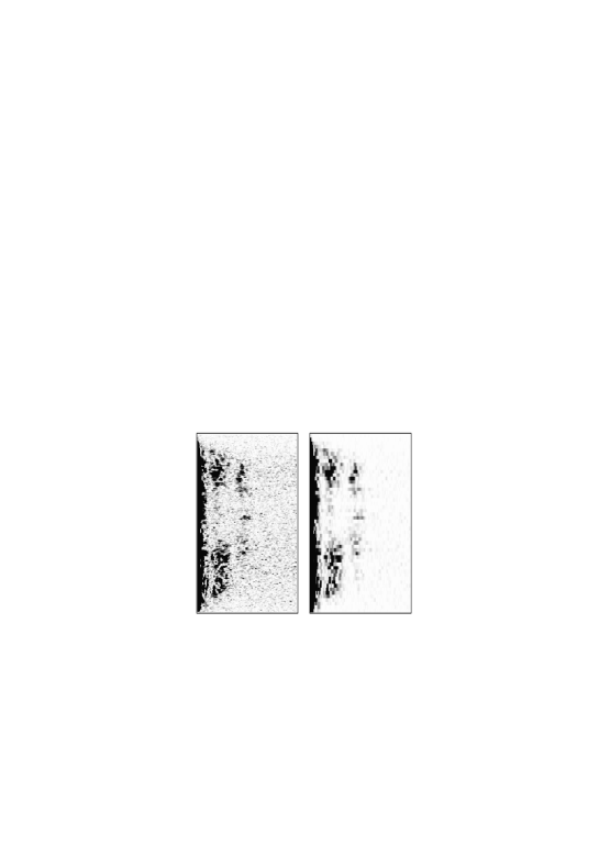
Observations were also made of the double star Cen (HR 4819), which has equal components separated by 1.2′′ H+S. The position angle of the observation was chosen so that the separation vector of the two stars was almost perpendicular to the axis of the cylindrical lens. In this way, the projected separation of the binary along the interferometer direction was only 0.15′′. The left panel of Figure 4 shows the row-by-row power spectrum of a single 0.2-second exposure. The vertical stripes are the clear signature of a double star.
The right panel of Figure 4 shows the row-by-row power spectrum of the same data, but here the original image was binned eight rows at a time before transforming. Each row, instead of projecting to 0.9 cm on the primary mirror, now projects to 7 cm. Thus, by binning several rows together, we have been able to increase the “slit” width in post-processing and decrease the noise from photon statistics, as can be seen in the figure. In practice, the optimum binning factor would depend on the atmospheric coherence length () at the time of observation and could be determined during data reduction. In fact, as shown by ? (?), the optimum aperture size for measuring visibilities is not the same as for closure phases. With MODS data one would be able to accommodate this by varying the binning factor in post-processing.
The analysis of MODS data, as with conventional speckle and NRM techniques, proceeds by estimating the power spectrum and closure phases of the object. The first step is to calculate the row-by-row power spectrum, as described above. Calibration for atmospheric and instrumental effects would be done using similar observations of an unresolved reference star. The result would be a series of measurements of the object power spectrum at many different spatial frequencies. Estimates of the closure phase would be obtained in a similar way by calculating the row-by-row bispectrum. Together, these visibility amplitudes and closure phases would be used either to fit a model or to produce and image by deconvolution. These processes are now standard in optical interferometry — the advantage of the MODS system is the multiplexing of data collection.
4 Discussion and conclusions
The observations reported here have shown the feasibility of using a cylindrical lens for Extended NRM and for MODS. In these test observations, the detector scale was not optimal in that the vertical direction was oversampled. In principle, only one or two pixels are required across each -sized strip on the pupil. Oversampling increases the contribution from readout noise and, unlike the case of photon noise, this cannot be reduced by rebinning in post-processing. The best solution would be to use a more powerful cylindrical lens, which would reduce the height of the pupil image. Alternatively, the effective pixel size on the CCD could be increased by on-chip binning.
For MODS observations, no aperture mask is used and so there is no need to form an intermediate pupil image. Thus, an existing speckle camera could be modified to perform MODS merely by inserting a cylindrical lens in front of the telescope focus. The lens should be positioned so as to image the telescope pupil onto the focal plane. It is not hard to show that the height of the re-imaged telescope pupil would be equal the focal length of the cylindrical lens divided by the focal ratio of the telescope beam. For example, at the coudé focus of the AAT, a cylindrical lens with mm would produce a pupil image 2.8 mm high.
With such a modified speckle camera, measurements at different position angles could be obtained by rotating the cylindrical lens. Unless the detector were also rotated, this would require the detected image to be de-rotated before one could perform the row-by-row analysis described above, but such rebinning should not present serious problems. Reconstructing a two-dimensional image from this series of one-dimensional measurements is a standard procedure, as described for example by ? (?). Since MODS uses the full pupil, the number of detected photons is the same as for conventional speckle (neglecting any slight reflective losses from the extra lens). The advantage is a higher signal-to-noise on individual visibility and closure phase measurements, at the expense of requiring observations at several different position angles.
How would the performance of a speckle camera be enhanced by this modification? The same number of photons would be collected, so one should not expect a large change in the limiting magnitude. Nor would MODS bring any improved resistance to variations in the seeing. However, there would be a gain in angular resolution. This arises because a one-dimensional pupil gives more weight to the longer baselines. It has been demonstrated that NRM can resolve binaries stars with the AAT down to separations of 15 mas RBA99, whereas full-aperture speckle has only given useful results with 4-m class telescopes for separations above about 25 mas. In addition, observations using MODS would spread the starlight more uniformly over the detector, making detector non-linearities much less important. This is especially useful for detectors that employ an image intensifier, which are common in speckle cameras, and is seen by ? (?) as the most important advantage of pupil apodization at optical wavelengths.
The main feature of MODS is that it confines the high-resolution information to one dimension, thereby increasing the contrast of the speckle pattern and improving the SNR of the visibility and closure phase measurements. As discussed by ? (?), this allows measurement of closure phases in regions of the bispectrum that would otherwise be useless. The key advantage of MODS is therefore an ability to image similar objects to speckle with higher fidelity and dynamic range. Image quality is frequently an important issue in extracting science from speckle images, so there is clearly a potential for the MODS technique to make an important contribution.
References
- (0) 1977A+R77 Aime, C., & Roddier, F., 1977, Opt. Commun., 21, 435
- (1)
- (1) 1993Bec93 Beckers, J. M., 1993, ARA&A, 31, 13
- (2)
- (2) 1993BvdLZ93 Bedding, T. R., von der Lühe, O., Zijlstra, A. A., Eckart, A., & Tacconi-Garman, L. E., 1993, ESO Messenger, 74, 2
- (3)
- (3) 1994BRM94b Bedding, T. R., Robertson, J. G., & Marson, R. G., 1994, A&A, 290, 340
- (4)
- (4) 1997BZvdL97 Bedding, T. R., Zijlstra, A. A., von der Lühe, O., Robertson, J. G., Marson, R. G., Barton, J. R., & Carter, B. S., 1997, MNRAS, 286, 957
- (5)
- (5) 1988aBus88 Buscher, D. F., 1988a. In: Merkle, F. (ed.), High-Resolution Imaging by Interferometry, p. 613, ESO: Garching
- (6)
- (6) 1988bBus88b Buscher, D. F., 1988b, MNRAS, 235, 1203
- (7)
- (7) 1993B+H93 Buscher, D. F., & Haniff, C. A., 1993, J. Opt. Soc. Am. A, 10, 1882
- (8)
- (8) 1990BHB90 Buscher, D. F., Haniff, C. A., Baldwin, J. E., & Warner, P. J., 1990, MNRAS, 245, 7p
- (9)
- (9) 1994Han94 Haniff, C. A., 1994. In: Robertson, J. G., & Tango, W. J. (eds.), IAU Symposium 158: Very High Angular Resolution Imaging, p. 317, Dordrecht: Kluwer
- (10)
- (10) 1987HMT87 Haniff, C. A., Mackay, C. D., Titterington, D. J., Sivia, D., Baldwin, J. E., & Warner, P. J., 1987, Nat, 328, 694
- (11)
- (11) 1992HGG92 Haniff, C. A., Ghez, A. M., Gorham, P. W., Kulkarni, S. R., Matthews, K., & Neugebauer, G., 1992, AJ, 103, 1662
- (12)
- (12) 1995HST95 Haniff, C. A., Scholz, M., & Tuthill, P. G., 1995, MNRAS, 276, 640
- (13)
- (13) 1982H+S Hirshfeld, A., & Sinnott, R. W. (eds.), 1982, Sky Catalogue 2000.0, Cambridge University Press
- (14)
- (14) 1997KEM97 Klückers, V. A., Edmunds, M. G., Morris, R. H., & Wooder, N., 1997, MNRAS, 284, 711
- (15)
- (15) 1988Kul88 Kulkarni, S. R., 1988. In: Merkle, F. (ed.), High-Resolution Imaging by Interferometry, p. 595, ESO: Garching
- (16)
- (16) 1978Lab78 Labeyrie, A., 1978, ARA&A, 16, 77
- (17)
- (17) 1989NKG89 Nakajima, T., Kulkarni, S. R., Gorham, P. W., Ghez, A. M., Neugebauer, G., Oke, J. B., Prince, T. A., & Readhead, A. C. S., 1989, AJ, 97, 1510
- (18)
- (18) 1996NegReg96 Negrete-Regagnon, P., 1996, J. Opt. Soc. Am. A, 13, 1557
- (19)
- (19) 1999RBA99 Robertson, J. G., Bedding, T. R., Aerts, C., Waelkens, C., Marson, R. G., & Barton, J. R., 1999, MNRAS, 302, 245
- (20)
- (20) 1997THB97 Tuthill, P. G., Haniff, C. A., & Baldwin, J. E., 1997, MNRAS, 285, 529
- (21)
- (21) 1991Wei91 Weigelt, G., 1991. In: Wolf, E. (ed.), Progress in Optics, p. 295, Vol. xxix, North-Holland: Amsterdam
- (22)
- (22) 1996WBH96 Weigelt, G., Balega, Y., Hofmann, K.-H., & Scholz, M., 1996, A&A, 316, L21
- (23)
- (23) 1992WBB92 Wilson, R. W., Baldwin, J. E., Buscher, D. F., & Warner, P. J., 1992, MNRAS, 257, 369
- (24)