The Face-on View of the Milky Way:
Gas Dynamics in the COBE NIR Bulge and Disk
Abstract
We report simulations of the gas flow in the gravitational potential of the COBE NIR bulge and disk. These models lead to four–armed spiral structure between corotation of the bar and the Sun, in agreement with the observed spiral arm tangents. The 3-kpc-arm is identified with one of the arms emanating from the ends of the bar.
University of Kentucky, Dep. of Physics & Astronomy, USA, ppe@pa.uky.edu \affilAstronomisches Institut der Universität Basel, Switzerland, gerhard@astro.unibas.ch
1 Introduction
The first face-on map of our Galaxy was constructed by Oort, Kerr & Westerhout (1958) from 21 cm observations, interpreting the observed gas velocities in terms of circular motions in a thin disk. This map revealed many arm–like features in the gas distribution. More recent surveys of atomic hydrogen, molecular gas, HII regions, giant molecular clouds (GMC), and other spiral arm tracers have helped to constrain the location of Galactic spiral arms. The majority of observations appear to be consistent with a four armed spiral pattern as suggested by Georgelin & Georgelin (1976); see the review in Vallée (1995).
The gas in the inner Galaxy is not on circular orbits, however. This is most evident from the so–called ‘forbidden’ velocities which would then imply gas in counterrotation. The most prominent example is the 3-kpc-arm, which appears in the -diagram at negative radial velocities on both sides of the galactic center. In the direction of the galactic center this arm is seen in absorption, which indicates that it passes between the Sun and the Galactic center.
In recent years, near-IR observations with the COBE satellite have motivated a series of new studies aiming to understand the dynamics of the inner Galaxy. The NIR maps obtained with DIRBE clearly show signatures of non-axisymmetric structure in the Galactic bulge. Dwek et al. (1995) used parametric bar models to determine the basic properties of this triaxial bulge.
Full advantage of the observed asymmetries was taken by Binney, Gerhard & Spergel (1997; BGS), who applied a newly developed Richardson–Lucy deprojection algorithm. By assuming that the bulge has three mutually orthogonal planes of symmetry, they recovered approximately the 3D distribution of NIR light in the Galactic center. For their favored bar inclination of , the bulge has axis ratios 10:6:4 and semi–major axis . It is surrounded by an elliptical disk that extends to . Outside the bar, the deprojected near IR luminosity distribution shows a maximum down the minor axis.
Here we report gas dynamical simulations in this model and compare to the observed spiral arm structure of the Galaxy. To follow the gas flow we have used a two-dimensional (2D) ‘smoothed particle hydrodynamics’ (SPH) method, which has a large dynamical range in resolution and can include self-gravity. We assume an isothermal equation of state. See Englmaier & Gerhard (1998; EG) for more details.
| Spiral arm tangents in longitude | Measurement | ||||
| 29 | 50 | -50 | -32 | HI, Weaver (1970) Burton & Shane (1970), Henderson (1977) | |
| 24, 30.5 | 49.5 | -50 | -30 | integrated 12CO, Cohen et al. (1980), Grabelsky et al. (1987) | |
| 25, 32 | 51 | 12CO clouds, Dame et al. (1986) | |||
| 25, 30 | 49 | warm CO clouds, Solomon et al. (1985) | |||
| 24, 30 | 47 | -55 | -28 | HII-Regions (H109-), Lockman (1979), Downes et al. (1980) | |
| 32 | 46 | -50 | -35 | 26Al, Chen et al. (1996) | |
| 32 | 48 | -50,-58 | -32 | -21 | Radio , Beuermann et al. (1985) |
| 29 | -28 | -21 | , Hayakawa et al. (1981) | ||
| 26 | -47 | -31 | -20 | , Bloemen et al. (1990) | |
| 30 | 49 | -51 | -31 | -21 | adopted mean |
| 54 | -44 | -33 | -20 | Model without halo | |
| 50 | -46 | -33 | -20 | Model with halo | |
2 Large scale morphology

Here we describe the gas flow in the deprojected mass model of BGS for , and assume that the potential rotates with a constant pattern speed , such that the corotation radius falls between the molecular ring and the 3-kpc-arm at . The morphology of the gas flow (Fig. 2) is insensitive to the choice of these parameters within reasonable bounds; see EG.
In these models a four armed spiral pattern forms, driven by the rotating triaxial bulge and elliptical disk, and the strong mass concentrations on the bar minor axis with negative quadrupole moment. The latter are presumably signatures of the spiral arm heads of the arms embedded in the molecular ring at radius. The model arm tangents can be identified with the five observed arm tangents (see Table).
The model arms also give a reasonable representation of the locations of HII regions and GMC’s in the -diagram (see Fig. 1). Finally, the model gives a good approximation for the terminal velocity curve (TVC), and hence the Galactic rotation curve, for without including a dark halo component. The observed TVC is used to fix the unknown velocity scale of the model, assuming a distance to the galactic center and an LSR velocity .
3 3-kpc arm and counter arm
One spiral arm in the model qualitatively corresponds to the 3-kpc-arm. The tangent of the model arm is at the correct longitude, however, the non-circular motion at is somewhat smaller than for the observed 3-kpc-arm. It has always been a puzzle why we do not see a symmetric counter arm for the 3-kpc-arm at the far side of the galaxy. The counter arm in our model runs almost parallel in the -diagram to another arm which ends at about . In fact, the observed arm there is known to split into two parts; see the two concentrations of warm CO clouds at and , indicating the presence of two shocks (Solomon et al. 1985; arrows in Fig. 1).
4 Effect of spiral arm gravity
Our model does not include a live stellar disk. Thus the gravitational force of the stellar spiral arms is not included. However, we can use the gaseous arms as tracers to estimate the influence of stellar spiral arms: We take a fraction of the mass from the stellar background disk model and add it to the mass in gas particles. This extra mass does not, however, enter the hydrodynamical equations. Then we smooth the potential of the extra mass over , to mimic the fact that the stellar arms are much broader than gaseous arms.
The resulting gas flow is similar to the previous one, in particular, the spiral arm tangents are hardly changed. The most significant difference is that now the 3-kpc-arm displays just the right amount of non-circular motion. In nature, gaseous spiral arms are driven by stellar spiral arms. In our model, however, both are driven by the bar and the non-axisymmetric features in the disk.
5 Comparison to GMC’s and HII regions
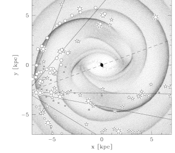
The idea of a four armed spiral pattern goes back to Georgelin & Georgelin (1976), who used HII regions as tracers for spiral arms. In Fig. 2 we compare the face-on view of our model to the tracer positions inferred from their and other more recent studies including surveys of GMC’s (see EG for references). Note that this plot does not take into account the non-circular motions of the tracers. Correcting for this effect will focus the points towards the spiral arms, due to velocity crowding; thus the correspondence will improve.
This work was supported by the Swiss NSF grants 21-40’464.94 and 20-43’218.95, and the NASA grants WKU-522762-98-6 and NAG5-3841.
Beuermann, K. et al., 1985, \aap, 153, 17 \referenceBinney, J.J., Gerhard, O.E. & Spergel, D., 1997, \mnras, 288, 365 \referenceBloemen, J.B.G.M. et al., 1990, \aap, 233, 437 \referenceBurton, W.B., Shane, W.W., 1970, IAU Symp. 38, eds. W. Becker, G. Contopoulos, Reidel, Dordrecht, p. 397 \referenceChen, W. et al., 1996, \aaps, 120, 315 \referenceClemens, D.P., 1985, \apj, 295, 422 \referenceCohen, R.J. et al., 1980, \apj, 239, L53 \referenceDame, T.M. et al., 1986, \apj, 305, 892 \referenceDownes, D. et al., 1980, \aaps, 40, 379 \referenceDwek, E. et al., 1995, \apj, 445, 716 \referenceEnglmaier, P. & Gerhard, O.E. 1998, \mnras, in press \referenceGeorgelin, Y.M., Georgelin, Y.P., 1976, \aap, 49, 57 \referenceGrabelsky, D.A. et al., 1987, \apj, 315, 122 \referenceHayakawa, S. et al., 1981, \aap, 100, 116 \referenceHenderson, A.P., 1977, \aap, 58, 189 \referenceLockman, F.J., 1979, \apj, 232, 761 \referenceOort, J.H., Kerr, F.T. & Westerhout, G., 1958, \mnras, 118, 379 \referenceSolomon, P.M. et al., 1985, \apj, 292, 19 \referenceVallée, J.P., 1995, \apj, 454, 119 \referenceWeaver, H., 1970, IAU Symp. 38, eds. W. Becker, G. Contopoulos, Reidel, Dordrecht, 126