Warped accretion discs and the long periods in X-ray binaries
Abstract
Precessing accretion discs have long been suggested as explanations for the long periods observed in a variety of X-ray binaries, most notably Her X-1/HZ Her. We show that an instability of the disc’s response to the radiation reaction force from the illumination by the central source can cause the disc to tilt out of the orbital plane and precess in something like the required manner. The rate of precession and disc tilt obtained for realistic values of system parameters compare favourably with the known body of data on X-ray binaries with long periods. We explore other possible types of behaviour than steadily precessing discs that might be observable in systems with somewhat different parameters. At high luminosities, the inner disc tilts through more than 90 degrees, i.e. it rotates counter to the usual direction, which may explain the torque reversals in systems such as 4U 162667.
keywords:
accretion discs — binaries: close — X rays: binaries — stars: individual: Cyg X-2, Her X-1, LMC X-4, 4U 1626671 Introduction
Soon after the discovery of Her X-1 (Tananbaum et al. 1972) it was found that beside the 1.24-sec pulse period and the 1.7-day orbital period (marked by eclipses of the neutron star by the companion) the system displayed another (‘long’ or ‘third’) period: a 35-day cycle of X-ray on and off states. Photometric variations showed a period of 1.6 days, the beat period between the orbital and long periods. A phenomenological ‘clockwork’ model in which the system contains a retrogradely precessing disc was found to explain the photometry quite well. The photometric variations are due to the varying amount of area of the disc facing us, as well as variations in the fraction of the star that is eclipsed when the disc passes in front of it and the variable X-ray illumination of the star (Gerend & Boynton 1976, Deeter et al. 1976). The behaviour is not strictly periodic: there are ‘anomalous’ on- and off-states in X rays, and the period of the cycle varies by 5–10% over time (Ögelman et al. 1985). With time, two more systems were found with nearly strictly periodic long variations: SS 433 has jets which precess around the sky every 164 days, and therefore presumably so does the underlying disc, and the direction of precession is retrograde (see Margon 1984). LMC X-4 has a 30.4-day long period, which resembles that of Her X-1 in many ways, except that the amplitude is much lower due to the fact that the companion star is much brighter (Heemskerk et al. 1994).
The success of the clockwork model quickly led to the general acceptance of the basic hypothesis that the long periods are due to precessing tilted accretion discs (Katz 1973, Roberts 1974). It appears easy to make a disc in a binary precess, since the companion star exerts forces on the disc which, when averaged over the orbit, lead to a constant rate of retrograde precession of a tilted annulus in the disc. The problem is to understand how the disc as a whole can precess at one rate, since the precession frequency is a strong function of radius in the disc, and how it remains tilted, i.e. avoids sinking back into the orbital plane on a viscous time scale. Roberts proposed that the disc is slaved to a companion whose spin is misaligned with the orbit (Roberts 1974). But that is difficult on general grounds: all neutron star binaries have eccentric orbits soon after the neutron star has formed, due to the effects of the supernova explosion. But now most (notably Her X-1) have orbits that are accurately circular, indicating that tidal forces have been strong enough to damp this initial eccentricity. It is hard to see how they would at the same time not have largely damped out a spin-orbit misalignment (Petterson 1977), since the spin angular momentum is much less than the orbital angular momentum for such binary systems.
Beside the three very regular and clear third periods mentioned above, there are many systems where a less well-defined variability exists. Some are quite regular but of more uncertain nature, e.g. Cyg X-1 (294 d; Priedhorsky, Terrell & Holt 1983) and 4U 182030 (176 d; Priedhorsky & Terrell 1984a). Others are simply less regular, such as Cen X-3 (120–160 d; Priedhorsky & Terrell 1983). In this latter category numerous objects have recently been added with well-sampled light curves obtained with the Rossi X-ray Timing Explorer (RXTE). Cyg X-2 (78 d; Wijnands, Kuulkers & Smale 1996) and X 2127119 (37 d; Corbet, Peele & Smith 1997) have periods that seem fairly stable, but the amplitude and light curve shape are variable so the periodicity cannot always be seen equally well. SMC X-1, on the other hand, has a fairly stable amplitude but a period that slowly decreases from over 60 d to under 50 d in the first 600 days of RXTE data (Wojdowski et al. 1997).
Moreover, there appears to be some evidence of discs precessing progradely. First, there has been a detection of an 11.2-day period in the light curve of Cyg X-2 (Holt et al. 1976). This is the beat period between the 78-day long period and the 8.9-day orbital period, but only if the disc precesses progradely. Note that this cannot be due to tidally forced precession. In X 1916053, the optical period is 0.9% longer than the X-ray period, and if the beat period of 3.8 days between the two is interpreted as the period of disc precession, it would most easily be for a progradely precessing disc.
It was noted by Petterson (1977) and Iping & Petterson (1990) that a sufficiently strong illumination from the centre could cause a disc to maintain a warped, tilted shape. While probably qualitatively correct, their results suffer from the use of an incorrect equation of disc evolution (see Papaloizou & Pringle 1983). An accretion disc is indeed unstable to tilting and warping due to radiation reaction forces when the luminosity of its central source exceeds a critical value (Pringle 1996, 1997). We examine here the consequences of this instability for the behaviour of discs in X-ray binaries. We show that the instability provides a mechanism for sustaining a tilted disc and making it precess with a period that agrees well with the observed long periods in X-ray binaries such as the famous 35-day period of Her X-1. They also provide the possibility of both prograde and retrograde precession. There are also non-steadily precessing solutions with time-varying tilt. We explore these in Section 3 after discussing the numerical solution method to the basic equation, which is derived in Section 2. Then we apply the results to some of the known long periods in X-ray binaries and to some similar systems that do not have observed long periods (Section 4). Finally, we discuss some implications and limitations of our findings (Section 5) and summarise our conclusions (Section 6).
2 Equation of motion for an irradiated disc in a binary
The accretion disc is assumed to be thin and Keplerian and is divided up into annuli that interact with each other via viscous forces, which has the advantage that only the evolution on the longer viscous time scale needs to be followed. The relevant equation of motion reads
| (1) | |||||
The first three terms on the righthand side were derived by Papaloizou & Pringle (1983, eq. 2.4) and further discussed by Pringle (1992, eq. 2.8). They conserve angular momentum exactly. The independent variables are and we work in a non-rotating frame centred on the accreting point mass (with the axis normal to the orbital plane). is the unit vector normal to the disc at radius , so is the local tilt angle of the disc plane and the azimuth of the tilt. is the disc surface density, and is the angular momentum per unit area. The assumption of Keplerian rotation implies . is the viscosity associated with the shear, whereas the viscosity associated with the shear that damps the misalignment between neighbouring annuli is . The term involving is the effect of the torque induced by irradiation from the central object:
| (2) |
where the dimensionless vector is an integral along the annulus that describes the purely geometric part of the torque (see Pringle 1996, 1997). is the luminosity of the central point source, which is assumed to radiate isotropically, and each element of the disc that is illuminated by the central source is assumed to re-radiate the incident radiation isotropically, causing a pressure perpendicular to the local disc surface.
The last term in Eq. (1) is the forced external precession due to the companion star tide. Let a companion of mass be located in the plane at . To lowest order in the torque on an annulus of width d can be obtained by integrating the force along an unperturbed circular orbit. The force on an element of the annulus at position is
| (3) |
The torque on the annulus is then simply obtained by integrating the elemental torque contributions along it. Here we expand the force in powers of and only retain the lowest non-vanishing order of the torque:
| (4) |
Note that the only force taken into account is the gravity of the companion. Since our frame is centred on (but not rotating) and thus revolves around the centre of mass of the binary, there is a centrifugal force as well. It is not hard to show that it contributes no net torque on an annulus. Comparison with the expression for leads to the expression for the precession frequency:
| (5) | |||||
| (9) |
In this paper, we shall make the approximation that the orbital period of the binary is small enough compared to the precession period that we may average the precession over the binary orbital period (i.e. over the angle ). Averaging and cross-product are not interchangeable, of course, so we have to average the torque (Eq. (4)) and then find a new expression for . The result is:
| (10) |
(See also Katz et al 1982, Papaloizou & Pringle 1983). Note that the factor is not present in studies that assume the inclination to be small.
For numerical studies we cast the equation in dimensionless form. The dimensionless variables are , and , with , and values to be determined later. Then we can also set , , and . Then if we measure time in units of the viscous time scale in the disc, i.e. , we obtain:
| (11) | |||||
where , and the dimensionless strength of the radiation field is given by
| (12) |
2.1 Analytic considerations
The stability to warping of a disc described by Eq. (1) can be analysed by linearising the disc tilt evolution (eq. 3.5 of Pringle 1996) in . Then and we can write its evolution as an equation for . We further assume that we are far from the disc edges, so that constant and . Then with we can write the following equation for :
| (13) |
where . The local stability then follows by looking for solutions of the form , with . Substituting in Eq. (13) this implies
| (14) |
The complex part of is identical to that of Pringle, so neither the addition of forced precession nor retention of the gradient terms affects the local linear stability of the disc. Thus, as before, growing modes occur only for and and their line of nodes follows a leading spiral. At finite amplitudes the effect of forced precession is strong because , so it will make the disc precess more rapidly towards the outside and thus tends to destroy the shape of the growing mode.
3 Numerical experiments
3.1 Numerical Method
The numerical method employed is that described in Pringle (1997), with changes made in order to model accretion discs in binary systems rather than in AGN. The most important changes which need to be made are with regard to tidal truncation of the disc at the outer edge, with regard to the input of mass at some radius other than the outer edge, and with regard to the tidally forced precession of the outer disc elements.
We work initially with 40 grid points between and , and use an equally spaced rather than a logarithmic grid (Section 3.2). This was chosen so that the outer edge of the grid would be properly resolved, but has the disadvantage that the inner disc regions are not well resolved. However, because of this, the computation time required for each run is relatively short, and thus we were able to explore a large volume of parameter space. We report below (Section 3.3) on a few runs carried out with a more extensive grid. The number of azimuthal zones was normally 68. Increasing this value to 120, which we did in a few key runs, had no effect on the results.
We achieve a zero torque inner boundary condition in the manner described in Pringle (1997) by removing mass over three zones centred on . We add material at a constant rate over 3 zones centred on radius . The material is added to the disc with specific angular momentum vector corresponding to the material being added in the orbital plane, and magnitude appropriate for the radius .
In order to take account of the tidal truncation of the disc at radius (), we need to set up a boundary condition which removes angular momentum at that radius but does not remove mass. Since the main dependent variable employed is the angular momentum density , this must of necessity employ some approximation. We find that the simplest method of achieving the desired effect is to calculate at each time step the amount of mass external to , to set the contents of those zones to zero, and to add the mass to the zone just internal to , with the same specific angular momentum as the matter already in that zone. In this way it was intended to minimise the chance of the outer tidal truncation resulting in any (unphysical) instability. Indeed no such instabilities were observed. This boundary condition should correspond to the combined conditions of and at .
The forced precession caused by the tidal potential field is handled as follows. Each annulus is precessed at each time step about the vector (0,0,1) at a rate . Thus we have ignored the factor of present in the forced precession rate (Equation 1.6). This could be simply included, but should be negligible for the kind of solutions we are looking for. The time step is limited to ensure that any annulus is not precessed by more than in any one time step. In practice the time step considerations for stability of the numerical method ensure that the precession rate is not the dominant factor in limiting the time step.
We assume a viscosity of the form:
| (15) |
which is chosen to approximate the viscosity dependence in such discs (see eq. 19). We take . The disc is set up initially with a surface density appropriate to a steady disc with this viscosity and with the appropriate boundary conditions (viz. at , at , and a dimensionless mass input rate of unity at ). The disc is given an initial warp of the form of a prograde spiral which is such that increases from zero at to at , with increasing by an angle of one radian over the same distance.
3.2 Numerical Results
We have investigated the non-linear behaviour of irradiated discs in binary systems, taking shadowing fully into account. Our aim has been to discover what regions of parameter space (if any) give rise to discs with a finite, and (reasonably) steady tilt angle of the kind which might be relevant to explanations of systems like Her X-1/HZ Her. Thus our initial aim was to search for the kind of ‘mode-like’ behaviour discussed by Maloney & Begelman (1997). We found, however, that the time-dependence of binary accretion discs gives rise to a richer and more varied behaviour than can be described by simple ‘modes’.
3.2.1
With an eye on the parameters of the binary systems we are interested in as shown in Table 3, we choose . We initially set the forced precession rate to zero, and investigate what values of the disc luminosity () give rise to relevant behaviour. In Figure 1 we show the behaviour of the inclination of the outer disc edge as a function of dimensionless time for various values of . We find that for the disc irradiation is not strong enough to lead to instability and the disc flattens into the orbital plane.

For the disc tilt settles down to a steady functional form, with small at the inside, and positive at most radii, reaching a value of (corresponding to an angle of ) at the outside (i.e. at ). The disc is warped in the shape of a prograde spiral, as is to be expected for a disc unstable to self-irradiation (Pringle 1996). At the same time the whole disc precesses steadily in a retrograde direction with a dimensionless period of . The direction of precession is retrograde because of the shape of the disc. The sign of determines which face of the disc is illuminated by the central source. A positive leads to retrograde precession (Pringle 1996). We note that this contrasts with the AGN discs discussed in Pringle 1997. There the outer boundary condition ensured that the outer edge of the disc remained in the initial disc plane. Then if the inner disc is tilted, much of the disc is likely to have negative , and therefore precesses in a prograde fashion. In the binary case the edge of the disc is free in the sense that no torque acts there to change the tilt of the disc.
Similar behaviour occurs when , although in this case at the outside settles down to the larger value of (corresponding to an angle of ) and to a more rapid retrograde precession rate with a period .
When the effect of radiation is further increased, the disc behaviour is no longer steady. The behaviour of at the outer radius is shown in Figure 1. The behaviour is in the form of a limit cycle. We note here that for simplicity we have assumed that is constant throughout each run. However, in reality, since the radiation illuminating the disc comes directly from the accretion rate at the disc centre, is likely to vary with time when the disc displays such non-steady behaviour. Thus the actual disc behaviour is likely to be yet more complicated than we find here.
3.2.2
In this section we describe the effect on the steady precessing solutions of adding retrograde forced precession of the form induced by tidal torques from a companion. The magnitude of the forced precession is described by the parameter (eq. 24). With zero forced precession, , we have seen (Section 3.2.1) that the disc settles down in the shape of a prograde spiral, with an increasing function of , reaching at the outer edge, and precessing steadily in a retrograde direction with period .
When a small amount of retrograde forced precession is added, the disc settles down to a similar behaviour as for , but with the final value of slightly increased, and the precession rate also increased. Thus we find that for , and ; for , and , and for , and . However, as the forced precession rate is increased further the disc instability is removed. Thus, for , we find that tends to zero, and the disc settles down into the orbital plane. We suggest that this behaviour comes about because in order to be unstable the disc must take the form of a prograde spiral (Pringle 1996). However strong retrograde forced precession, which is differential in the sense that the precession rate increases with radius (here ), tends to unwind the prograde spiral and thus acts to prevent the instability from occurring.
3.2.3
Here we investigate the effect of adding forced retrograde precession on the solutions discovered in Section 3.2.1 which take the form of limit cycles. We therefore investigated solutions with , and with , , and . Increasing the forced precession rate seems to have little effect on the amplitude of the limit cycle, until at the value of the instability is quenched altogether, and the disc settles into the orbital plane. However the period of the limit cycle is affected, and decreases with increasing , from a value of 200 for to a value of about 120 for . While these limit-cycle solutions are partly an artefact of the small grid, the damping of even these high-luminosity solutions illustrates the how powerful forced precession is in suppressing disc tilts.
3.2.4
One effect of adding material at in the previous sections was to help pin the disc towards the orbital plane at that radius. This helped to control the behaviour of the disc within that radius (see also Section 3.3), and to allow the outer regions of the disc (a factor of three in radius) to evolve freely with regard to tilt. Since the self-irradiation warping instability acts more strongly at larger radii, it was always the outer regions of the disc which responded most to the radiation flux from the central object. In this section we describe the effect of changing the radius at which mass is added to the disc from to . This has two major effects. First, adding matter closer to the outside has the effect of tending to pin the disc into the orbital plane at the outside, while allowing the inner disc regions to tilt (see also Section 3.3). Second, a steady disc inside the radius has constant at radii inside , whereas a steady disc with a outer boundary condition has for radii outside . Thus for a given accretion rate, since is typically an increasing function of both and , the outer parts of the disc become less massive as is decreased. Thus by increasing from 10 to 20, we expect the radiation instability to require larger values of .
For values of , we find that the disc is stable to self-irradiation. For values of the inner parts of the disc turn over completely in the manner discussed for the AGN discs in Pringle 1997. For the disc does tend to a fairly steady configuration. However the shape of the disc now differs from those discussed above in the sense that the disc tilt is largest at the inside, and decreases with radius (i.e. is predominantly negative; Fig. 2). Moreover the inner and outer parts of the disc behave in quite different and independent manners. The inclination at all radii in the disc oscillates more or less in phase with a period of about . The innermost radii oscillate between and 0.57, and the outermost radii oscillate between and 0.12. At radius , the oscillation in varies between 0 and 0.14, and it is this radius which appears to separate the inner and outer parts of the disc. The inner part of the disc (roughly those radii ) has an inclination which decreases with radius, and which precesses in a prograde direction with a period of about . The outer parts of the disc (roughly radii in the range ) have (on a time average) an inclination which increases with radius and precess in a retrograde direction with a period of about . The precession in the inner regions proceeds at a more or less steady rate. However the azimuth of the tilt of the outer edge of the disc stays almost constant for each oscillation period of the inclination, and then jumps by a certain amount (which then gives the mean outer precession period). It should be noted that the oscillation frequency of the inclination is the sum of the moduli of the precession frequencies of the inner and outer parts of the disc (i.e. ).

3.2.5
We now investigate the effect of adding retrograde forced precession to the disc which was described in the previous section. As the magnitude of increases from zero, the behaviour of the disc stays initially the same, except that the inclination decreases, the inner (prograde) precession period, , increases, and the outer precession period, , decreases. Thus, in comparison with , and for , we find that for , , , ; for , , , ; for , , , ; and for , , and . In addition, as the size of is increased, the radius which separates the inner disc and outer disc behaviours (the radius at which the oscillation passes through zero) moves outwards until at it is at the outer edge to within the resolution of the grid. However when is increased further to the whole disc now settles to a constant profile, which is positive at all radii, and has , and decreasing with radius. The disc as a whole precesses in a prograde direction with period . The shape of the disc is such that it has a prograde spiral inside , and a retrograde spiral outside .
3.3 Numerical results on a more extensive grid
Since all the numerical results above were computed on a grid which had limited resolution in the inner regions, we felt that it was necessary to explore the limitations of such a procedure. We use a logarithmic grid consisting of 80 grid points between and . We still add material over 3 grid points centred on , and we remove material over 3 grid points centred on . In this manner the outer part of the grid between and is reasonably well resolved (15 grid points), and the inner disc region extends inward of by almost two orders of magnitude, so that the behaviour of the inner parts of the grid can now be modelled more accurately.
Because the grid is now more extensive, and especially because the grid now extends to smaller radii (where viscous time scales are shorter) the computational run times are now longer by about two orders of magnitude. Thus we have limited ourselves to a few representative examples for comparison with the results in the previous section. We find that the instability sets in at values of which are larger by about a factor of two. This comes about because in a steady accretion disc with an inner boundary condition corresponding to vanishing surface density (i.e. zero torque), it is the quantity which is constant with radius, rather than just . Thus the effect of moving the inner boundary inwards is to increase the surface density of the outer disc by about a factor of two.
Since the tidally induced precession does not seem to play a strong role for those discs which are relevant to the X-ray binaries we are interested in here, we have taken . In Figure 3 we show the behaviour of the disc inclination at for = 0.09, 0.12, 0.135, 0.15, 0.175, 0.2 and 0.3. As can be seen the disc with is stable. The disc with eventually precesses in a steady fashion in a retrograde direction with a period of about 35, and the disc inclination at the outer edge settles down to a value of 0.15 (i.e. about 8.5 degrees). The disc with settles down to a solution in which the inclination and oscillates with a period of about 15 and semi-amplitude 5 per cent, about a steady value for the inclination of 0.25 (14 degrees). The precession period is 30 for the outer disc. The inner disc has inclination near zero, with small oscillations of the same period as the outer disc (Figure 4). The period of these oscillations is the beat period between the inner and outer disc periods, as with the small grid. Their cause is simply that the region where the outer and inner disc join (just outside ) tries to adjust to the tilts of both sides. This it cannot do simultaneously, of course, and the tilt of this zone oscillates between nearly zero and a finite value, depending on the relative phase between the inner and outer disc solutions. This oscillation is then communicated throughout the disc, with an amplitude that decreases away from the contact zone.
For greater , the inner disc suddenly gets a substantial tilt as well, presumably because it too is now unstable (the sudden transition is caused by the fact that the inner radius of the unstable region decreases as the inverse square of , see Pringle 1997). The discs with and 0.3 vary chaotically, with the tilt of the inner disc usually greater than 90 degrees, and that of the outer disc less. The outer disc still precesses retrogradely on average, with roughly the same period as before (25–35), but with irregularities superimposed. The azimuth of the inner disc tilt wanders irregularly without any long-term trend.


In conclusion we find that the results obtained with the larger grid are fully consistent with the behaviour found with the cruder grid. Thus the results presented in Section 3.2 are expected to be reasonably representative. The main differences appear to be that the larger grid has a larger surface density (for the reasons explained above) and so goes unstable for somewhat larger values of , that the range of for which the disc displays steady, or nearly steady, precessing tilted behaviour is somewhat larger, and that the tilt angles reached by the outer disc are somewhat smaller. In order to check the grid-dependence of these large simulations we further doubled the number of radial and azimuthal grid points in a few key simulations; no significant changes in the results were observed.
3.4 Precession periods and stability
In order to see how well simple estimates work, we now compare the precession periods obtained in the simulations with expected values. From Eq. (11), one obtains a precession time scale estimate, taking to be unity:
| (16) |
where . Now , where , and thus at the outside edge of the disc,
| (17) |
We now have to take the quantities from simulations to compare the left and righthand sides numerically. Using the results from Sect. 3.2.1, we have, e.g. a numerical period of 48 when . At the outer edge of this simulation, and , giving a predicted period from Eq. (17) of , in very good agreement with the value seen in the simulation. For the run with we have , and hence compute , compared with the actual simulation value of 58. It is clear that the radiative time scale at the outer edge of the grid predicts the numerical precession period quite accurately. The high precision is doubtless somewhat fortuitous, since shadowing will tend to lengthen the period at the grid edge somewhat (), whereas the fact that the pattern speed must be an average over a finite range of radii in the disc tends to shorten it, because the radiative time scale becomes shorter at smaller radii.
The critical number for stability is the ratio of radiative to viscous time scales at the outer disc edge. In the scaled equations, we have
| (18) |
In analogy with Pringle (1997, eq.3.9) we can then define a critical value , such that discs with will be unstable to radiative warping. Since its precise value will depend on boundary conditions, it has to be evaluated from appropriate numerical simulations. There was a difference in the critical value of between the large and small grids we explored, and we surmised that this was due to their different outer-edge surface densities. The evaluation of should be independent of this. For the small grids, the critical value of is 0.045, and with at , we deduce . For the large grids, the smallest unstable is 0.09, and for this simulation at , resulting in . The excellent agreement between the two cases confirms that we understand the difference between the stability in the large and small-grid simulations. The fact that we find a three times smaller than Pringle (1997) did for simulations geared to AGN (i.e. without a tidal truncation on the disc) does demonstrate the need for re-determining for different types of system if one wants to go beyond order of magnitude estimates (see also Maloney, Begelman & Novak, 1998).
3.5 Summary of numerical results
Since we have presented the results of a variety of numerical computations, using two different numerical grids, it would seem prudent at this stage to provide a brief summary of the basic results we feel that we have learnt from them.
The results from both grids agree that for values of that are too small the disc is stable against the tilting instability. They further agree that for values of above the critical value for instability by not more than about 30 per cent, the disc takes on a fixed shape, with inclination increasing to (at most) around 20 degrees at the outside (dependent on ) and in the form of a prograde spiral, and precesses steadily in a retrograde direction (at a rate also dependent on ). The extent of the outer part of the disc which is able to display this behaviour depends to some extend on the radius at which mass is added to the disc. For values of slightly larger than this, the disc displays similar behaviour in the mean (i.e fixed disc shape and steady retrograde precession), but has an oscillatory behaviour superimposed upon this due to the fact that the inner and outer disc precess in opposite directions, which means that in the zone where they meet there is no stationary solution and the tilt oscillates at the beat period between the inner and outer disc precession periods. This oscillation is communicated throughout the disc, with an amplitude that decreases away from the contact region.
We have used the smaller grid, which has higher spatial resolution at the outer disc edge, in order to investigate the effects of tidally induced differential (retrograde) precession. The basic effect of differential precession on a tilted disc is to flatten the disc out into the plane normal to the precession axis (e.g. Pringle, 1992; Scheuer & Feiler 1996), and this seems to be the case here. Note that even the non-linear behaviour which occurs for large values of is damped by the imposition of forced differential precession.
The results from the two grids do not agree on the non-linear development of the disc tilt for large values of . The large grid, extending a factor of over 200 in radius shows that, as was found for discs in an AGN type environment (Pringle 1997), the disc can become completely inverted for large enough values of . The disc then displays chaotic behaviour as a result of the interaction between disc self-shadowing, which stabilises the outer disc, and the viscous time-delay between the outer and inner disc radii. In contrast the small grid indicates that the disc undergoes periodic relaxation oscillations. It seems likely that this behaviour is the result of too few grid points being available to provide an sufficiently accurate description of the disc shape and dynamics. The stability analysis and precession periods for marginally unstable discs, however, agree very well between the large and small grids if one accounts for their difference in surface density.
4 Application to some observed systems
4.1 Numerical values of the coefficients
4.1.1 Viscosity
As usual, the viscosity in an accretion disc is very uncertain. We shall make the standard assumption of an disc (Shakura & Sunyaev 1973) which radiates the generated heat locally. In the range of temperatures and densities relevant to the outer regions of accretion discs in bright X-ray binaries, the dominant radiative opacity is bound-free, . For solar abundance material, . Using the standard assumptions we get the viscosity as a function of and , from which we eliminate using (i.e. assuming we are far from the disc edge). This gives
| (19) |
(; ; ). Since we measure time in units of the viscous time at the inner edge of the disc only the radial scaling enters into our calculations directly.
When mass is added at a radius which is significantly less than the outer disc radius the usual steady-state disc assumption does not apply for . Instead, we have a regime of zero radial velocity, which implies const. (Pringle 1996; prime denotes radial differentiation). This results in . We can then compute the disc temperature by equating half the local dissipation rate, to the local emission rate from each disc surface. Since at its inner edge this part of the disc does connect to a regime where follows from the accretion rate in the usual way we can still set the normalisation of the outer-disc surface density from the accretion rate. The net result is the same as above (eq. 19), but with an additional factor . We do not consider any discs with , so we have ignored the small correction to the viscosity in our calculations. Note that the surface density is significantly affected, changing from inside to outside, so that the outer disc becomes significantly lighter and more susceptible to radiative warping when mass is injected well within .
4.1.2 Disc size and mass input
In a binary system the accretion stream emerging from the companion at L1 initially has a non-circular orbit, but once it self-intersects it settles in a circular orbit with radius which has the same specific angular momentum about the accreting object as the incoming stream. This radius is tabulated by Flannery (1975) for , where . We find that his calculations are well fitted by
| (20) |
where is the semi-major axis of the orbit. On a viscous time scale, the ring spreads inwards and outwards; the outward expansion is halted by tidal angular-momentum extraction when the disc approaches the Roche radius. We adopt the outer radii calculated by Papaloizou and Pringle (1977) as a function of mass ratio, which to a good approximation give ; here is the volume-average Roche radius of the accretor, for which we use the approximation formula by Eggleton (1983). The inner edge of the disc is either near the surface of the compact object or near the magnetopause, and it is at least 3 orders of magnitude smaller than . Simulations with very large values of are very time consuming. Setting in the numerical studies proved adequate, although we undertake some calculations with (Section 3.3).
An important issue is where matter enters the disc, and here there is a clear hysteresis. If the disc is stable, mass enters it at the outer edge because it is stopped from further infall by the matter already present. But if the disc is tilted out of the plane, the incoming stream does not stop until it hits the line of nodes or reaches the point of closest approach for a ballistic orbit, approximately . In practice, therefore, there is a variation of the input radius with the relative phase between orbit and precession that introduces extra short-term variations in the disc. In the spirit of our present approximation of neglecting these rapid variations, we add matter to the disc in a small region around , where most of the mass would be added in a more realistic case. Because a flat disc with input at the edge has a significantly higher surface density than the corresponding tilted disc, this means that X-ray sources can display a hysteresis effect: if a binary with a long period temporarily decreases in brightness, for whatever reason, and remains less luminous for a few outer-disc viscous times, it will not necessarily return to its long period when the luminosity is restored to the previous level, because the now higher density means that a higher luminosity is needed to re-establish the warp than was needed to maintain the previously established one.
4.1.3 Time scales
There are three time scales that characterise the competing processes of viscous damping, forced precession, and radiative growth. In the disc regime and for the above viscosity, their values are
| (21) | |||||
| (22) | |||||
| (23) | |||||
Here measures the radiative efficiency of the accretion process. The radiative growth time, , is especially uncertain because various factors may intervene to make the radiation absorbed by a disc element different from (and usually less than) what we would estimate from our direct observations of the X-ray flux. In particular, the central source may not radiate completely isotropically. And furthermore, estimating the X-ray flux intercepted by the disc from its brightness in the UV/optical is complicated by the fact that only a fraction of the incident flux is absorbed, where is the disc albedo. For X rays incident perpendicular to a stellar atmosphere, values of in the range 0.3–0.5 apply, but for the grazing incidence we have here it may be less. Simultaneous measurements of the X-ray and reprocessed optical fluxes from X-ray binaries imply very small fractions, , of reprocessed radiation. For example, the effective temperature of the disc in Cen X-4 implies (Heemskerk & van Paradijs 1989). In X-ray bursts with coincident detection of bursts of reprocessed optical radiation the implied value of is at most (see Van Paradijs & McClintock 1995). It is not likely that such low values are entirely the result of albedo; possibly, the outer parts of the disc are shadowed from the central source, due to non-monotonic behaviour of the disc thickness. Since in warped discs the tilt is usually rather larger than the expected disc thickness, this effect is probably not so important in our present considerations. In all, we cannot expect the measured precession times to agree with the simple calculations here to better than a factor few. Below we shall make the comparison between the observed long periods and expected radiative periods, where we estimate the latter as in view of the results from Sect. 3.4.
4.2 System parameters and simulation parameters
In order to determine which numerical parameters are relevant to a given binary system we have to know the binary parameters and compute the appropriate values of various numerical parameters. In particular we need estimates of the value of at , , which is a measure of the strength of the instability, of , which is the relevant dimensionless measure of the forced precession rate at the outer disc edge, and of and . In Table 1 we list the basic parameters of a number of X-ray binaries. Most contain neutron stars, for which a mass of 1.4M⊙ has been assumed. Parameters derived from the basic ones are given in Table 2.
| name | ||||||||||
|---|---|---|---|---|---|---|---|---|---|---|
| (days) | (M⊙) | (M⊙) | (days) | |||||||
| LMC X-4 | 1. | 408 | 1. | 4 | 16. | 3. | 30. | 4 | ||
| Cen X-3 | 2. | 09 | 1. | 4 | 18. | 0. | 9 | 140. | ||
| SS433 | 13. | 10. | 20. | 10. | 164. | |||||
| X 1907097 | 8. | 38 | 1. | 4 | 20. | 0. | 05 | 42. | ||
| LMC X-3 | 1. | 7 | 10. | 6. | 3. | 198. | ||||
| SMC X-1 | 3. | 9 | 1. | 4 | 18. | 4. | 55. | |||
| Cyg X-1 | 5. | 6 | 16. | 33. | 2. | 5 | 294. | |||
| Her X-1 | 1. | 7 | 1. | 4 | 2. | 35 | 0. | 25 | 35. | |
| X 2127119 | 0. | 713 | 1. | 4 | 0. | 9 | 0. | 01 | 37. | |
| Cyg X-2 | 9. | 844 | 1. | 4 | 0. | 7 | 1. | 78. | ||
| gen. LMXB | 0. | 2 | 1. | 4 | 0. | 5 | 0. | 1 | 0. | |
| X 1916053 | 0. | 035 | 1. | 4 | 0. | 1 | 0. | 1 | 3. | 8 |
| 4U 162667 | 0. | 029 | 1. | 4 | 0. | 03 | 0. | 05 | 0. | |
| name | ||||||||||||||||
|---|---|---|---|---|---|---|---|---|---|---|---|---|---|---|---|---|
| (days) | (days) | (days) | ||||||||||||||
| LMC X-4 | 11. | 4 | 9. | 5 | 0. | 20 | 1. | 7 | 0. | 26 | 53. | 8. | 1 | 7. | 4 | |
| Cen X-3 | 12. | 9 | 13. | 0. | 19 | 2. | 2 | 0. | 26 | 110. | 12. | 13. | ||||
| SS433 | 2. | 50. | 0. | 32 | 14. | 0. | 25 | 890. | 100. | 110. | ||||||
| X 1907097 | 14. | 3 | 34. | 0. | 19 | 5. | 4 | 0. | 26 | 800. | 47. | 62. | ||||
| LMC X-3 | 0. | 6 | 11. | 0. | 42 | 3. | 9 | 0. | 29 | 250. | 21. | 62. | ||||
| SMC X-1 | 12. | 9 | 19. | 0. | 19 | 3. | 3 | 0. | 26 | 110. | 22. | 11. | ||||
| Cyg X-1 | 2. | 1 | 34. | 0. | 32 | 9. | 4 | 0. | 25 | 900. | 44. | 180. | ||||
| Her X-1 | 1. | 7 | 6. | 5 | 0. | 34 | 1. | 9 | 0. | 25 | 130. | 14. | 17. | |||
| X 2127119 | 0. | 64 | 3. | 1 | 0. | 42 | 1. | 1 | 0. | 29 | 180. | 8. | 7 | 31. | ||
| Cyg X-2 | 0. | 5 | 17. | 0. | 44 | 6. | 6 | 0. | 30 | 420. | 140. | 29. | ||||
| gen. LMXB | 0. | 36 | 1. | 2 | 0. | 47 | 0. | 51 | 0. | 33 | 34. | 3. | 3 | 8. | 5 | |
| X 1916053 | 0. | 07 | 0. | 36 | 0. | 60 | 0. | 19 | 0. | 50 | 10. | 1. | 8 | 4. | 0 | |
| 4U 162667 | 0. | 02 | 0. | 31 | 0. | 68 | 0. | 18 | 0. | 75 | 12. | 4. | 0 | 4. | 9 | |
For most of the simulations, we use a disc that extends from to . Since the inner disc does not matter much for our results we scale the parameters for each system so that in the system corresponds to the truncation radius in the numerical grid. Mass is added to the disc at (see Table 3). The appropriate value of follows from
| (24) | |||||
depends on the details of viscosity because it measures the precession rate, which is independent of viscosity, in units of the viscous time which is of course viscosity-dependent. In the numerical grids, . From the simulations in Sect. 3.2.5, correcting by a factor 2 for the higher surface densities implied by the large grids (Sect. 3.3), we find that tidal shear destroys the warp of a disc near the stability limit when is about 0.003, which means . This implies that most systems have little enough forced precession to have their warps survive (Table 3), but not by much; also forced precession may somewhat shorten retrograde long periods (Sect. 3.2.2).
Similarly, can be related to the parameters of a real system via
| (25) | |||||
Note that does not depend on details of the viscosity. This is because both the surface density and the viscous time scale are inversely proportional to the viscosity, so the effect that a lower-viscosity disc has a longer damping time for disc tilts is exactly compensated by the fact that its mass also increases the growth time of the radiative instability. In table 3 we list the values of the numerical parameters that follow from these relations for all systems in table 1. We also list , which is the real time that passes in each system per unit of dimensionless time in the simulation.
| name | ||||||||
|---|---|---|---|---|---|---|---|---|
| (days) | ||||||||
| LMC X-4 | 21. | 0. | 022 | 7. | 8 | 0. | 38 | |
| Cen X-3 | 28. | 0. | 020 | 7. | 9 | 0. | 75 | |
| SS433 | 27. | 0. | 020 | 7. | 5 | 6. | 3 | |
| X 1907097 | 54. | 0. | 012 | 7. | 9 | 5. | 7 | |
| LMC X-3 | 37. | 0. | 039 | 8. | 8 | 1. | 8 | |
| SMC X-1 | 16. | 0. | 016 | 7. | 9 | 0. | 81 | |
| Cyg X-1 | 65. | 0. | 032 | 7. | 5 | 6. | 4 | |
| Her X-1 | 30. | 0. | 021 | 7. | 6 | 0. | 94 | |
| X 2127119 | 66. | 0. | 027 | 8. | 6 | 1. | 3 | |
| Cyg X-2 | 9. | 6 | 0. | 011 | 9. | 1 | 3. | 0 |
| gen. LMXB | 32. | 0. | 040 | 9. | 8 | 0. | 24 | |
| X 1916053 | 17. | 0. | 066 | 15. | 0. | 07 | ||
| 4U 162667 | 9. | 2 | 0. | 067 | 22. | 0. | 08 | |
4.3 Comparing forced and radiative precession with data
Let us now assume that the disc radii in real binaries are adequately approximated by , and that the disc tilt is big enough that mass input occurs predominantly at . Then we can predict what the forced and radiative precession time scales are for all the systems in table 3 and compare them with their observed long periods.
For forced precession, a particularly simple relation ensues if we divide the result by the orbital period:
| (26) |
Since is only a function of mass ratio, so is the whole right-hand side. This presents us with a natural ordering of the systems by mass ratio, which is shown in Fig 5. The curve predicted by Eq. (26) is also shown, and while it is within an order of magnitude of the data, it does not appear to predict the observed values well at all. Specifically, even an arbitrary vertical shift of the predicted line cannot fit the data well, simply because no trend of the observed long periods with mass ratio is evident in the data, and both at mass ratio unity and at mass ratio 10 the observed values range over a factor 15. Thus a reasonable fit can be obtained only by omitting some of the data points (Larwood 1998).

When we repeat the exercise to test the radiative precession model there is not one simple system parameter with which the times scale, so we plot the same ordinate as in the previous figure versus the predicted ; a rather different picture results (Fig. 6). There is a reasonable correlation between predicted and observed periods over the range of a factor 40 in , with a mean ratio somewhat below unity (note that there was no adjustment of the normalisation). Since there is some freedom in the choice of disc albedo and parameter, we can adjust the mean ratio of predicted to observed period to be one, e.g. by setting (Sect. 4.4). Then most systems come within a factor 2 of the curve, with the exception of Cen X-3 and X 1907097, which for very similar predicted periods have a factor 14 difference in observed long period. (Note that they also have almost the same mass ratio, so forced precession faces the same problem of a large difference between systems predicted to be the same.) On the general ability to predict long periods, the radiative precession model therefore does much better than tidally forced precession. It is perhaps remarkable that SS 433, which is said to have a thick disc and for which our model should therefore not be valid, fits the relation rather well. One might wish to consider the possibility that the (outer) disc of SS 433 subtends a large solid angle not because it is intrinsically thick, but because it is strongly warped and tilted.

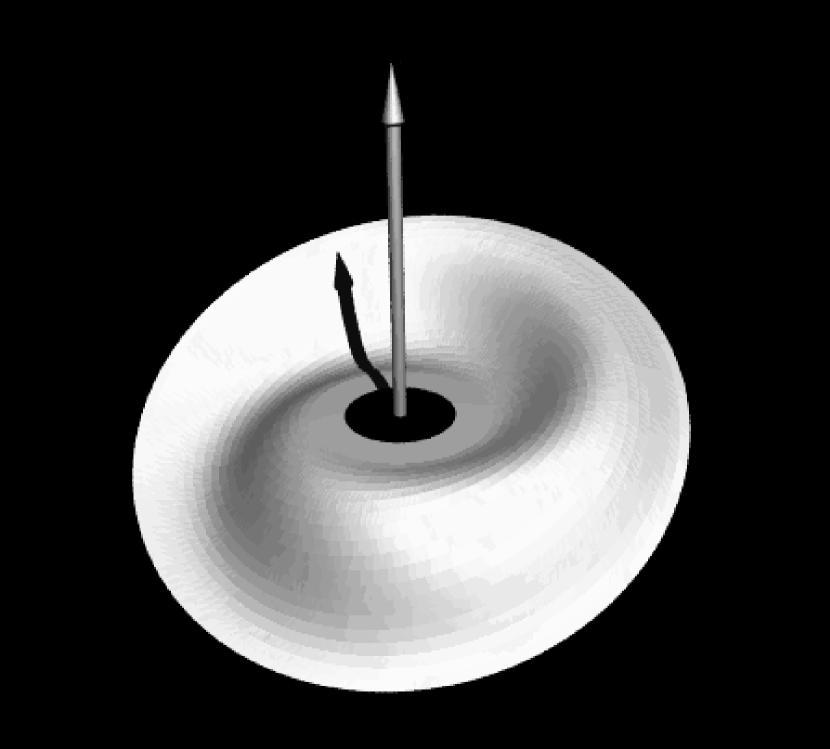
Our model can be tested further by probing directly the shapes of the discs using eclipse mapping and reverberation mapping. In Fig. 7 we show the shape of the disc as seen in a simulation of a fixed-shape retrogradely precessing outer disc that might correspond to the case of Her X-1. Note the flaring towards the outer edge and the near alignment with the orbital plane inside the mass input radius. We remind the reader that the range of luminosities over which these stationary solutions exist is quite narrow (We found it to be only 30%). But whether Her X-1 has a constant tilt is not really known, though large variations in the outer-disc tilt appear not to be needed to explain the photometry. However, the source is known to have anomalous on- and off states or dips (Giacconi et al. 1973), which could well be caused by a variation of the disc tilt. In Fig. 8 we show a projection of the disc onto the sky as seen from the central source. An observer at infinity would be represented by a straight line at constant latitude as the disc precesses. When the line is clear of the disc, which can happen either once or twice per precession period, the observer sees an on state of the X-ray source. For low inclinations, one sees two on states of different length (Fig. 9), once when the line of sight passes under the disc (short-on) and once when it passes over it (long-on).


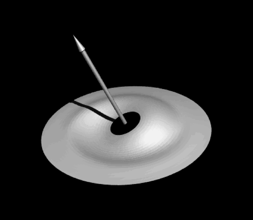
By contrast, a progradely precessing disc such as perhaps that of Cyg X-2 has its highest tilt in the middle. A typical example is shown in Fig. 10. When mass input in such a disc is not at the very outside edge the outer part can be going in a retrograde direction at the same time, with a different period (Sect. 3.2.4). Under favourable inclinations an observer could see both the outer and inner disc periodicities in the sequence of X-ray on and off states. An example of this is shown in Fig. 11.

4.4 Hercules X-1
For the specific case of Her X-1, where a relatively stable cycle exists over a long time, and the retrograde precession has been established well from observations, we may look at the numbers in somewhat greater detail. Using and Eq. (21), we can establish a maximum possible radiative precession time scale
| (27) | |||||
where we have used the parameters of Her X-1 from our tables. The stable long period indicates that Her X-1 must be within 30% of the stability boundary (Sect. 3), so supposing we equate this period to the actually observed value of 35 d, this gives
| (28) |
If we then use (Kumar and Pringle 1985, Ogilvie 1998) we find , which is not an unreasonable value (see Section 5). Note that our results imply quite generally that the measurement of a precession period constitutes a crude measurement of the disc viscosity.
Rather than assuming near-criticality, we may also just compute from Eq. (22) to get
| (29) |
which shows good agreement with the observed 35-d period for reasonable values of and .
4.5 Very long periods: 4U 182030 and X 1916053
Two well-documented long periods which are not shown in Figs. 5 and 6 are the 176-day period of 4U 182030 and the 199-day period of X 1916053 (Priedhorsky & Terrell 1984b). The reason is that both would be very far off the top of the vertical axis: these periods are too long in such compact binaries to be a disc precession period. For 4U 182030 the bursting behaviour changes with the 176-day cycle, suggesting that indeed the accretion rate varies though the cycle rather than just the aspect of a disc. In X 1916053 a third star orbiting the binary has been advanced as the cause of the very long period (Grindlay et al. 1988).
4.6 Torque reversals
Some X-ray pulsars with long and well-sampled pulse period records show very extended epochs in which the spin period decreases, followed by equally long spindown epochs. A famous example is 4U 162667 (Nelson et al. 1997, Chakrabarty et al. 1997), and another is GX 14. We note that in our simulations many of the more luminous discs are tilted through more than 90 degrees in their inner parts (Figure 4), implying that they are rotating counter to the usual direction and would provide a torque that is always spindown, assuming the pulsar spin is prograde relative to the orbit. The outer disc, at the same time, can be tilted much less strongly (Figure 3). Since the range in luminosity over which the discs are unstable but only have small tilt is fairly small, and since all X-ray binaries show long-term flux variations, it is quite possible that a few binaries have luminosities that vary around the value that separates prograde and retrograde inner discs. More detailed discussion of this torque reversal model is given in a companion paper (van Kerkwijk et al. 1998).
5 Discussion
5.1 Warp wave propagation
The equation we use to describe the time-evolution of the disc tilt makes the basic assumption that angular momentum is transferred between disc elements predominantly via viscous processes (Pringle 1992). However, fluid discs can also propagate angular momentum, and therefore warps, through wave-like processes (Lubow & Pringle 1993, Korycansky & Pringle 1995, Papaloizou & Lin 1995, Lubow & Ogilvie 1998). For wave-like propagation to dominate, it is necessary that the angular velocity in the disc be closely Keplerian, and for the viscosity to be sufficiently small (see the discussion in Pringle 1997). By closeness to Keplerian we mean that
| (30) |
throughout the disc, where is the epicyclic frequency. Making the approximation that the binary companion can be represented as a ring of mass at distance from the primary, mass , we find that, to a first approximation in (),
| (31) |
Taking the system parameters for Her X-1 in Tables 2 and 3 we find that near the edge of the disc, ,
| (32) |
By comparison we find that
| (33) |
Thus close to the disc edge we expect wave propagation to be marginally possible by this criterion, and to improve significantly at smaller radii.
However, for wave propagation we also require that the disc viscosity be sufficiently small. A disc warp wave in a Keplerian disc propagates a distance of order , before it is dissipated by viscosity. Thus for a wave to be able to propagate over a radial distance R, we require
| (34) |
Measurement of in the discs in the binary systems we are discussing is not easy, since the magnitude of the viscosity is best estimated from measuring the time scale on which the disc as a whole varies. However, good estimates for are available for a related set of binary systems, the X-ray novae. For these systems it is possible to parametrise the quantity by modelling the X-ray light curves through the outburst cycle (mainly the decline from outburst), and the result obtained, which it turns out also fits the outbursts of dwarf nova systems, is (Cannizzo, Chen & Livio, 1995)
| (35) |
For the value of appropriate here (eq. 33), this corresponds to
| (36) |
which is also in line with the values of required for discs in dwarf nova outbursts (e.g. Cordova 1995), and for the value of which we require to bring our calculations into agreement with the parameters of Her X-1 (Section 4.4).
Thus wave propagation can occur in these discs only if
| (37) |
We conclude that, in contrast to the calculations of Larwood (1998), the discs in binary X-ray systems are unlikely to be able to sustain propagating warp waves, and that the diffusion based approach is likely to provide a better description of the physics of warp evolution in these systems.
5.2 Possible consequences of some neglected effects
In all the simulations we used the time-independent expression for the forced precession, i.e. we assumed the precession period to be much longer than the orbital period. In reality is typically a few tens, but can be as low as 5. This means deviations from the smooth precession and extra nodding motions of the disc with periods that are beats between multiples of the precession and orbital periods can occur. These have in fact been seen in SS 433 and discussed in these terms (Katz et al. 1982). In addition to this short-period effect, mass input would also be influenced by the varying phase between companion star and disc: the accretion stream would first hit the disc somewhere along its curved intersection with the orbital plane, and the intersection radius would vary between the outer disc edge and the minimum distance of approach to the centre allowed by the stream’s angular momentum (about 0.5). So a more realistic simulation would either average the mass input over a large range in disc radii or have a time-variable mass input radius. Perhaps such effects could also explain the curious fact that in at least some systems (Her X-1, LMC X-4, and Cyg X-2) the precession period is an integer multiple of the orbital period.
The luminosity we used in any simulation was strictly constant. For all stationary solutions this should be valid, but the solutions in which the outer disc tilt is large and variable (i.e. at high luminosity; Sect. 3.3) are not strictly valid: their surface densities are rather lower when the tilt is large than when it is small, and since mass is added to the disc at a constant rate this must mean that the amount of mass passing through the inner disc edge varies with time, and therefore the central source luminosity should do so too. This extra feedback operates with a delay of order the outer disc viscous time, and such delayed feedback could lead to further instabilities (as any thermostat designer knows).
Schandl & Meyer (1994) and Schandl (1996) have studied the effects of a disc emitting wind. Like radiation the wind carries momentum and therefore its launch from the disc surface causes a force on the disc. Since the momentum per unit energy in a slow wind is much greater than in radiation this could be a more important effect. However, we understand the formation of winds only poorly and therefore the ab initio calculation of how much wind there is and how much momentum it carries away is difficult. Unfortunately, Schandl & Meyer neglected self-shadowing and used an older and incorrect equation of motion for the disc, so it is difficult to make a detailed comparison of the two models and the reasons why they differ. The predicted disc shapes are strikingly different though, so the issue may well be observationally decidable: their discs have tightly wound spirals with the angle between the line of nodes and the radial direction decreasing outward, whereas the radiative warps have very open spirals, and the angle of the line of nodes with the radial direction increases outwards. If the sonic point of the wind were close to the disc, unlike in the study by Schandl & Meyer, then the behaviour would be almost the same as for our radiation-driven precession, except that the force could be much greater for a given incident flux. This means that the region of instability moves to lower luminosities. Since value of we find for our model is not too far from the actual values in X-ray binaries, this would mean that wind-driven warping would give extremely unstable, erratic behaviour in those systems, which appears to contradict the regular behaviour of Her X-1.
6 Conclusion
We have examined the viability of radiation-driven warping and precession of thin accretion discs as a model for the long or third periods in X-ray binaries. The model holds up very well and has a number of advantages over earlier proposals. (i) It not only causes a disc to precess once tilted, but also gives rise to and maintains the tilt, whereas in previous models the origin of the tilt was always a difficult issue. (ii) The equation of motion for the disc we use does not suffer from the physical inconsistencies of some earlier proposed equations of motion. Also, unlike linearised approximations to the solutions of our equation in earlier papers and some other studies, this numerical study takes account of the important effects of self-shadowing of the disc. (iii) The quantitative agreement between the observed long periods of X-ray binaries and the results of our simulations is good, whereas forced precession due to the companion’s gravitational pull on the disc fares rather poorly when compared quantitatively with the data. Also, radiative precession can be prograde as well as retrograde, unlike forced precession. There is tentative evidence that the discs in Cyg X-2 and possibly X 1916053 do precess progradely. To put it succinctly, we have shown that if the radiative instability of Pringle (1996) gives rise to the disc tilt in these systems, then it also automatically gives rise to disc precession at approximately the observed rate. Moreover, we have also shown that if tidally induced precession becomes dominant, then the instability is likely to be stabilised, and the disc to remain in the orbital plane.
In addition to steadily precessing discs, radiative warps at high luminosity can also be non-stationary: their tilt angle varies periodically with time in our simulations, and in realistic cases with feedback between central source luminosity and accretion rate would probably exhibit non-periodic behaviour as well. This may be applicable to many of the long X-ray periods observed in nature, which are not very stable in amplitude and/or period.
One particular feature of high-luminosity systems is that the inner disc may tilt through more than 90 degrees, and thus rotate counter to the normal direction. When it encounters the magetosphere of a neutron star it will then provide a strong spin-down torque, possibly explaining the torque reversals seen in systems such as 4U 162667. One would expect the X-ray source to be behind the disc much of the time when the warp is so strong, but the strongly warped discs have much lower surface densities, so they could be (partly) transparent to X rays (van Kerkwijk et al. 1998).
Acknowledgements RAMJW gratefully acknowledges support from the Royal Society through a URF grant. We also thank M. Begelman and P. Maloney for useful discussions, and for a preprint of their paper.
References
- Cannizzo et al. 1995 Cannizzo, J., Chen, W., & Livio, M. 1995, ApJ 454, 880
- Chakrabarty et al. 1997 Chakrabarty, D., Bildsten, L., Grunsfeld, J. M., Koh, D. T., Prince, T. A., Vaughan, B. A., Finger, M. H., Scott, D. M., & Wilson, R. B. 1997, ApJ 474, 414
- Corbet et al. 1997 Corbet, R., Peele, A., & Smith, D. A. 1997, IAU Circ. 6632
- Cordova 1995 Cordova, F. A.-D. 1995, in X-ray Binaries, eds. , W. H. G. Lewin, J. van Paradijs, & E. P. J. van den Heuvel, Vol. 26 of Cambridge Astrophysics Series (Cambridge:Cambridge University Press), Chapt. 8, pp 331–389
- Deeter et al. 1976 Deeter, J., Crosa, L., Gerend, D., & Boynton, P. E. 1976, ApJ 206, 861
- Eggleton 1983 Eggleton, P. P. 1983, ApJ 268, 368
- Flannery 1975 Flannery, B. P. 1975, MNRAS 170, 325
- Gerend and Boynton 1976 Gerend, D. & Boynton, P. E. 1976, ApJ 209, 562
- Giacconi et al. 1973 Giacconi, R., Gursky, H., Kellogg, E., Levinson, R., Schreier, E., & Tananbaum, H. 1973, ApJ 184, 227
- Grindlay et al. 1988 Grindlay, J. E., Bailyn, C. D., Cohn, H., Lugger, P. M., Thorstensen, J. R., & Wegner, G. 1988, ApJ 334, L25
- Heemskerk and van Paradijs 1989 Heemskerk, M. & van Paradijs, J. 1989, A&A 223, 154
- Heemskerk and van Paradijs 1994 Heemskerk, M. H. M. & van Paradijs, J. 1994, A&A 223, 154
- Holt et al. 1976 Holt, S. S., Boldt, E. A., Serlemitsos, P. J., & Kaluzienski, L. J. 1976, ApJ 205, L143
- Iping and Petterson 1990 Iping, R. C. & Petterson, J. A. 1990, A&A 239, 221
- Jones and Froman 1976 Jones, C. & Froman, W. 1976, ApJ 209, L131
- Katz et al. 1982 Katz, J. F., Anderson, S. F., Margon, B., & Grandi, S. A. 1982, ApJ 260, 780
- Katz 1973 Katz, J. I. 1973, Nature 246, 87
- Korycansky and Pringle 1995 Korycansky, D. G. & Pringle, J. E. 1995, MNRAS 272, 618
- Kumar and Pringle 1985 Kumar, S. & Pringle, J. E. 1985, MNRAS 213, 435
- Larwood 1998 Larwood, J. 1998, MNRAS 299, L32
- Lubow and Ogilvie 1998 Lubow, S. & Ogilvie, G. 1998, MNRAS submitted
- Lubow and Pringle 1993 Lubow, S. H. & Pringle, J. E. 1993, ApJ 409, 360
- Maloney and Begelman 1997 Maloney, P. R. & Begelman, M. C. 1997, ApJ 491, L43
- Maloney et al. 1998 Maloney, P. R., Begelman, M. C., & Novak, M. A. 1998, ApJ 504, 77
- Margon 1984 Margon, B. 1984, ARA&A 22, 507
- Nelson et al. 1997 Nelson, R. W., Bildsten, L., Chakrabarty, D., Finger, M. H., Koh, D. T., Prince, T. A., Rubin, B. C., Scott, D. M., Vaughan, B. A., & Wilson, R. B. 1997, ApJ 488, L117
- Ögelman et al. 1985 Ögelman, H., Kahabka, P., Pietsch, W., Trümper, J., & Voges, W. 1985, Space Sci. Rev. 40, 347
- Ogilvie 1998 Ogilvie 1998, MNRAS in press
- Papaloizou and Pringle 1977 Papaloizou, J. & Pringle, J. E. 1977, MNRAS 181, 441
- Papaloizou and Lin 1995 Papaloizou, J. C. B. & Lin, D. N. C. 1995, ApJ 438, 841
- Papaloizou and Pringle 1983 Papaloizou, J. C. B. & Pringle, J. E. 1983, MNRAS 202, 1181
- Petterson 1977 Petterson, J. A. 1977, ApJ 218, 783
- Priedhorsky and Terrell 1984a Priedhorsky, W. & Terrell, J. 1984a, ApJ 284, L17
- Priedhorsky and Terrell 1984b Priedhorsky, W. & Terrell, J. 1984b, ApJ 280, 661
- Priedhorsky and Terrell 1983 Priedhorsky, W. C. & Terrell, J. 1983, ApJ 273, 709
- Priedhorsky et al. 1983 Priedhorsky, W. C., Terrell, J., & Holt, S. S. 1983, ApJ 270, 233
- Pringle 1992 Pringle, J. E. 1992, MNRAS 258, 811
- Pringle 1996 Pringle, J. E. 1996, MNRAS 281, 357
- Pringle 1997 Pringle, J. E. 1997, MNRAS in press
- Roberts 1974 Roberts, W. J. 1974, ApJ 187, 575
- Schandl 1996 Schandl, S. 1996, A&A 307, 95
- Schandl and Meyer 1994 Schandl, S. & Meyer, F. 1994, A&A 289, 149
- Scheuer and Feiler 1996 Scheuer, P. A. G. & Feiler, R. 1996, MNRAS 282, 291
- Shakura and Sunyaev 1973 Shakura, N. I. & Sunyaev, R. A. 1973, A&A 24, 337
- Tananbaum et al. 1972 Tananbaum, H., Gursky, H., Kellogg, E. M., Levinson, R., Schreier, E., & Giacconi, R. 1972, ApJ 174, L143
- van Kerkwijk et al. 1998 van Kerkwijk, M. H., Chakrabarty, D., Pringle, J. E., & Wijers, R. A. M. J. 1998, ApJ 499, L27
- van Paradijs and McClintock 1995 van Paradijs, J. & McClintock, J. E. 1995, in X-ray Binaries, eds. , W. H. G. Lewin, J. van Paradijs, & E. P. J. van den Heuvel, Vol. 26 of Cambridge Astrophysics Series (Cambridge:Cambridge University Press), Chapt. 2, pp 58–125
- Wijnands et al. 1996 Wijnands, R. A. D., Kuulkers, E., & Smale, A. P. 1996, ApJ 473, L45
- Wojdowski et al. 1997 Wojdowski, P., Clark, G. W., Levine, A. M., Woo, J. W., & Zhang, S. N. 1997, ApJ submitted