11 (11.13.2; 11.08.1; 11.09.4; 11.09.1 (M31); 02.16.2)
J.L. Han
New clues to the magnetic field structure of M31
Abstract
We observed 21 polarized background radio sources in the field of M31 at 1.365 GHz and 1.652 GHz, and determined their rotation measures (RMs). The RM data show that the regular magnetic field of the disk probably extends from about 5 kpc to 25 kpc from the center with similar structure. The RMs obtained from the polarized emission from M31 at 6 cm and 11 cm indicate that M31 might have a weak poloidal field in its tenuous halo. Observational features of the odd and even dynamo modes in a galaxy are discussed. An even mode (S0) dynamo may operate in M31.
keywords:
Galaxies: magnetic fields — Galaxies: halos — Galaxies: ISM — Galaxies: individual: M31 — Polarization1 Introduction
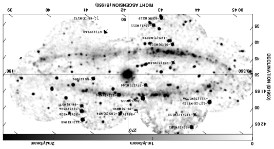
The bright “ring” of nonthermal radio emission (Pooley [1969]; Beck et al. [1998]. See also Fig. 1) at a radius of about 10 kpc in the disk of M31 (NGC 224, the Andromeda Nebula) is often referred to as basic evidence for the lowest mode of an axisymmetric dynamo (eg. Beck et al. [1996]). The regular magnetic field is aligned along the “ring” (Beck et al. [1980]; Beck [1982]; Beck et al. [1989]). Outside the “ring”, however, very little is known about the magnetic field, mainly because the polarized radio emission is very weak and superimposed onto extended emission from a foreground Galactic spur (Berkhuijsen [1972]; Gräve et al. [1981]).
The radio disk in galaxies often is radially more extended than the optical disk, sometimes also vertically. For example, radially extended radio emission was detected in M51 (see Fig.1 of Berkhuijsen et al. [1997]). Radio emission extending far away from the galactic plane was observed from NGC 4631 (Hummel et al. [1991]), NGC 891 (Sukumar & Allen [1991]) and a few other galaxies (eg. NGC 3432 by English & Irwin [1997]). In M31, extended Hi and optical emission was detected up to more than from the center along the minor axis (Emerson [1974]; Innanen et al. [1982]). However, the radio emission seems not that extended and the existence of a radio halo in M31 is still uncertain (eg. Wielebinski [1976]; Volodin & Dagkesamanskii [1978]; Gräve et al. [1981]; Berkhuijsen et al. [1991]). Our Galaxy has a vertically extended thick radio disk (Beuermann et al. [1985]) and rotation measures of extragalactic radio sources have revealed the existence of an extended magneto-ionic disk (Clegg et al. [1992]; Han & Qiao [1994]). In this paper, we will investigate the extended magneto-ionic disk in M31.
The detection of the regular magnetic field outside the “ring”, either interior to the “ring” or in the outer spiral arms or halo, will constrain the theoretical models for the type and origin of the field (eg. Poezd et al. [1993]; Howard & Kulsrud [1997]). A field residing just in the “ring” is very difficult to understand in the frame-work of a primordial field origin. More seriously, a dynamo cannot generate a field that is limited to a given small range of radius. The field should be much more extended (Moss et al. [1998]), and should have another weaker ring exterior (Ruzmaikin et al. [1988]) or interior to the observed “ring” (Moss et al. [1998]). The emission possibly detected interior to the “ring” from the inner arms (eg. Beck [1982]; Berkhuijsen et al. [1991]) is too weak for a measurement of the regular field.
M31 is a nearby spiral galaxy which optically extends more than along the major axis on the sky. There are a number of polarized background radio sources in the field of M31, which can be used as probes of the magneto-ionic medium in M31. If the magnetic structure in the halo or extended disk is somewhat ordered, the rotation measures (RMs) of these sources should have systematic deviations from the average. We observed 21 polarized radio sources with the VLA in 6 fields in the direction of M31 at two frequencies, and determined their RMs from the observed position angles (PAs). We present the observations and data reduction in Sect.2, the results in Sect.3, and discuss them in Sect.4.
| Field | RA(1950) | Dec(1950) | Polarized Sources |
|---|---|---|---|
| No. | hm s | ′ ′′ | (37W-No.) |
| B1. | 00 38 00.0 | +41 45 00 | 45,50,57,91 |
| B2. | 00 39 30.0 | +41 10 00 | 89,94,115,144 |
| B3. | 00 40 30.0 | +41 40 00 | 131,152,175 |
| B4. | 00 40 40.0 | +40 40 00 | 168,172 |
| B5. | 00 42 00.0 | +41 23 00 | 188 |
| B6. | 00 42 30.0 | +41 00 00 | 205,207B,211,219 |
| Object | RA(1950) | Dec(1950) | I1652 | PI1652 | p | PA1652 | PA1365 | RM | PAintri | Notes |
|---|---|---|---|---|---|---|---|---|---|---|
| 37W– | hm s | ′ ′′ | (mJy) | (mJy) | (%) | () | () | radm-2 | () | |
| 45a | 00 37 14.0 | 40 55 18.0 | 15.120.07 | 0.550.06 | 4 | 915 | 1685 | 1136 | 13410 | 1,2,3 |
| 50a | 00 37 30.2 | 40 52 09.1 | 16.000.34 | 0.710.06 | 4 | 165 | 1334 | 765 | 16311 | 1,2,3 |
| 50b | 00 37 29.7 | 40 52 35.0 | 7.600.16 | 1.700.07 | 22 | 252 | 1271 | 903 | 157 | 1,2,3 |
| 57 | 00 37 40.7 | 40 50 45.6 | 22.060.20 | 0.560.06 | 3 | 1185 | 423 | 866 | 10116 | 1,3 |
| 74A/B | 00 38 25.0 | 41 08 31.6 | 1055 | 14012 | 1,2,4 | |||||
| 89a | 00 38 55.2 | 41 14 04.8 | 13.990.17 | 0.520.06 | 4 | 345 | 1395 | 869 | 1820 | 1,2,3 |
| 89b | 00 38 55.3 | 41 14 12.7 | 13.450.17 | 1.080.07 | 8 | 233 | 1233 | 915 | 1511 | 1,2,3 |
| 91 | 00 38 57.2 | 40 47 08.0 | 41.540.77 | 1.350.07 | 3 | 1372 | 891 | 552 | 665 | 1,2,3 |
| 94a | 00 39 04.1 | 41 02 20.9 | 18.620.17 | 0.540.06 | 3 | 1435 | 3613 | 1229 | 1432 | 1,5 |
| 115 | 00 39 34.5 | 41 13 01.0 | 319.991.10 | 8.580.06 | 3 | 991 | 191 | 921 | 942 | 1,2,3 |
| 131 | 00 39 51.2 | 41 41 20.6 | 65.050.56 | 1.880.06 | 3 | 702 | 1681 | 932 | 685 | 3,5 |
| 144 | 00 40 07.3 | 41 10 09.3 | 21.260.15 | 0.390.05 | 2 | 507 | 1813 | 3717 | 12035 | 3,5 |
| 152 | 00 40 23.5 | 41 38 43.4 | 1.860.16 | 0.170.07 | 9 | 8013 | 1597 | 11517 | 11845 | 3,5 |
| 168 | 00 40 56.8 | 40 38 04.8 | 52.594.53 | 2.900.05 | 5 | 1771 | 1181 | 671 | 1241 | 3,5 |
| 172 | 00 41 10.0 | 40 30 10.2 | 143.892.26 | 2.700.14 | 2 | 812 | 212 | 683 | 316 | 3,5 |
| 175a | 00 41 15.2 | 41 40 53.0 | 39.690.35 | 1.180.06 | 3 | 434 | 1232 | 1115 | 7412 | 3,5 |
| 175b | 00 41 13.0 | 41 40 52.7 | 45.820.60 | 2.090.06 | 5 | 122 | 802 | 1273 | 736 | 3,5 |
| 188 | 00 41 39.6 | 41 14 17.7 | 5.800.28 | 0.290.05 | 5 | 1784 | 443 | 1525 | 10613 | 3,5 |
| 205 | 00 42 16.9 | 41 08 30.1 | 31.331.99 | 0.810.06 | 3 | 901 | 1113 | 919 | 8318 | 3,5 |
| 207B | 00 42 21.0 | 41 06 17.0 | 3.720.33 | 0.550.10 | 15 | 423 | 1105 | 1297 | 10815 | 3,5 |
| 211 | 00 42 27.0 | 40 55 09.0 | 20.890.34 | 4.200.06 | 20 | 381 | 1431 | 861 | 212 | 3,5 |
| 219 | 00 42 54.6 | 40 56 03.4 | 11.730.20 | 0.500.05 | 4 | 423 | 1487 | 839 | 2018 | 5 |
Notes: 1. PA value at 21 cm (1490 MHz) from Beck et al. ([1989]) is also considered; 2. As note 1 but at 6.3 cm (4760 MHz); 3. PA value at 1400 MHz from NVSS catalog (Condon et al. [1998]) is considered; 4. No flux desities are given because of no detection in our high-resolution observations. The RM is taken from Beck et al. ([1989]); 5. PA value at 1465 MHz from Beck et al. ([1998]) is considered.
2 Observations and data reduction
The observations were carried out at 1.365 GHz and 1.652 GHz simultaneously on October 19th, 1995, with the VLA B-array. We observed consecutively each of the 6 fields (pointings) for about 10 minutes. In all, three sets of 10 minutes of data were obtained for each field in three hours observation time. The coordinates of the field centers and the sources detected in the fields are listed in Table 1.
For our purpose, a high-resolution array is necessary that is “blind” to the extended radio emission of M31 without resolving the sources. Therefore, we chose the B-array with an angular resolution of about for our program. One observation band of 50 MHz width was centered on 1.365 GHz and another one of 25 MHz width on 1.652 GHz. 3C48 (B0134+329) and 3C138 (B0518+165) were observed at the beginning and the end, respectively, for primary flux calibration and polarization calibration.
We processed the data with the AIPS software package. After standard calibration and editing procedures, we used imagr with “robust” weighting to produce I, Q, U maps. Self-calibration iterations in phase and amplitudes were applied. Finally, we obtained the maps of linear polarized intensity (PI) and position angle (PA).
3 Rotation measures
The sources with significant linear polarization detected are shown in Fig. 1 and listed in Table 2. We give the identification numbers of the 37W catalog (Walterbos et al. [1985]) and positions from our observations. The total intensities I and polarized intensities PI at 1652 MHz are listed in the Table. (The data of these sources at 1365 MHz are available from the authors via email.) For some extended sources such as 37W207B and 37W219, we give the positions of the polarization peak. The uncertainty of the positions is normally about . The RMs were obtained by comparing the position angles at 1365 MHz and 1652 MHz. Published position angles at 21 cm (1490 MHz) and 6.3 cm (4750 MHz) from Beck et al. ([1989]), at 1400 MHz from the NVSS catalog (Condon et al. [1998]) and at 1465 MHz from Beck et al. ([1998]) were considered to solve the RM ambiguities, as indicated in the notes. For some resolved sources (eg. 37W050 with 4 components, 37W045 and 37W089 with two components), we list each polarized component separately with a mark “a” or “b” following its 37W catalog name. The RM of 37W074A/B from Beck et al. ([1989]) is included for the following discussion.
There are four or five possible contributions to the observed RMs of these sources: the foreground RM from our Galaxy, the RM contribution from the disk and/or the halo of M31, the intergalactic RM contributions (between M31 and the sources and between M31 and our Galaxy), and the intrinsic RMs from the sources themselves. The RM from the intergalactic medium is believed to be quite small. The intrinsic RMs of sources are difficult to address. The sum of the last two contributions is usually smaller than 10 rad m-2 for most sources as justified by the small RMs of sources at the Galactic poles (Simard-Normandin & Kronberg [1980]; Han et al. 1998), and therefore will not be considered below. The RM sky of our Galaxy is correlated in areas of about radius at the Galactic latitude of M31 (Oren & Wolfe [1995]; Simard-Normandin & Kronberg [1980]). The Galactic spur in front of M31 is also larger than M31 (Gräve et al. [1981]). In the region of sky around the direction to M31 , the fluctuations of foreground RM from our Galaxy should be small enough to ignore. The average foreground RM from our Galaxy over the observed area is rad m-2 (Berkhuijsen et al. in preparation).
Inspection of Fig. 1 shows that most RM values of the background sources do not deviate much from the average foreground RM. The RMs of three sources interior to the continuum “ring” differ most strongly. The RMs of most sources, however, are more or less consistent with the RM variation along the “ring” shown in Fig. 2 (see Sect.4.1).
4 Discussion
 |
 |
|
 |
 |
If the magnetic field in a galaxy is generated or maintained by a dynamo, theoretical simulations show that the lowest mode dynamo is excited most easily (eg. Beck et al. [1996]). The two lowest modes, the odd mode A0 and the even mode S0, could exist in galaxies. Observational proofs of these modes are obviously important, not only to further theoretical studies but also to discrimination between the dynamo theory and its alternatives, eg. primordial origin (eg. Kulsrud et al. [1997]), local origin (eg. Daly & Loeb [1990]), or MHD waves (eg. Fan & Lou [1996]).
As illustrated by Fig.19 in Wielebinski & Krause (1993), the toroidal field in the A0 mode is antisymmetric with respect to the galactic plane, and the poloidal field has the structure of a dipole (see our Fig. 3). The S0 mode field, however, has the same toroidal field structure above and below the plane, but an antisymmetric poloidal field, like two opposite dipoles.
Our Galaxy is an edge-on galaxy. Han et al. ([1997]) analysed the RM distribution of several hundred background sources, and showed that our Galaxy possibly has an A0 odd mode field, eg. an antisymmetric toroidal field with respect to the Galactic plane. For M31, the well-known “ring” is thought to be an indication of a toroidal field, but it is not clear yet whether it is of odd or even mode.
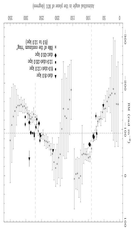
Polarization observations of M31’s extended emission show that there is a systematic RM variation around the observed “ring” located at a galacto-centric radius of about 10 kpc, as shown in Fig. 2, which is caused by the regular magnetic field inside the “ring” (Beck [1982]; Berkhuijsen et al. [1987]; Beck et al. [1989]; Berkhuijsen et al. in preparation). The gas layer causing the observed RM variations is primarily the near half, in contrast to the full thickness of the disk where the emission comes from. The RM variation with azimuthal angle of such a continuum “ring” should have the same shape for magnetic fields of the A0 odd mode and of the S0 even mode, but they differ in amplitude by a factor of 2 according to Beck et al. ([1996]). This difference cannot be used as a criterion to distinguish A0 or S0 mode, because it is not known to which mode the observed amplitude of the RM curve refers.
The RMs of the background sources reveal the average magnetic field across the full thickness of the disk. If the toroidal magnetic field of an S0 even dynamo mode is uniform in the disk of a galaxy, the RMs of background sources should be twice that of the extended emission from M31. On the other hand, for an A0 odd dynamo field the RM contribution from the toroidal field in the near half and the far half of the disk of M31 will cancel each other and therefore there will be no net RM contribution when observing background sources.
Observations of the RMs near the minor axis, either of background sources or of the extended emission from the “ring”, could provide evidence for a symmetric poloidal field of an even dynamo mode or an antisymmetric poloidal field of an odd dynamo mode. The toroidal field near these azimuthal regions is almost perpendicular to the line of sight and therefore contributes a negligible RM. Because of the poloidal field, the RMs of the sources along the lines of sight No.1 and No.5 (or No.2 and No.4) should similarly deviate from the average foreground RM in the odd mode, while opposite deviations should be found in the even mode (Fig. 3).
In the following we will consider that the deviating RMs of the observed sources are caused by the magneto-ionic medium in either the disk or the halo of M31, or both.
| Object | RM | 1 | 1,2 | 2 |
|---|---|---|---|---|
| 37W– | (rad m-2) | () | () | (kpc) |
| 188 | 15 | 52 | 7.3 | |
| 205 | 34 | 73 | 15.1 | |
| 207B | 39 | 76 | 16.8 | |
| 219 | 59 | 83 | 27.1 | |
| 211 | 62 | 84 | 23.7 | |
| 168 | 116 | 96 | 20.6 | |
| 172 | 118 | 96 | 26.0 | |
| 91 | 188 | 213 | 4.9 | |
| 57 | 215 | 253 | 15.8 | |
| 50 | 219 | 255 | 18.3 | |
| 45 | 225 | 258 | 22.3 | |
| 94 | 246 | 265 | 10.0 | |
| 74 | 259 | 268 | 18.7 | |
| 89 | 282 | 273 | 17.6 | |
| 115 | 302 | 278 | 11.4 | |
| 131 | 321 | 284 | 26.4 | |
| 144 | 329 | 289 | 5.3 | |
| 152 | 329 | 289 | 20.3 | |
| 175 | 342 | 302 | 15.4 | |
Notes: (1) Azimuthal angles , , and are shown in Fig.1. Just for these values, they are the same in the plane of sky and in the plane of M31. (2) We assumed an inclination of and a distance to M31 of 690 kpc.
4.1 On the toroidal field
The toroidal magnetic field in M31 results in a systematic RM variation around the observed “ring” (Fig.2). The slight phase shift of the RM curve (RM at and ) is due to the pitch angle of the field in the “ring”. A detailed discussion of this RM variation, including the big jumps (Beck 1982) near and /, will be given by Berkhuijsen et al. (in preparation).
The field in the “ring” contributes to RMs of the discrete sources if they are located behind the “ring”. However, if a source has a large angular separation from the “ring”, then the field in the “ring” will not affect its RM unless the field extends to that large radius. In Table 3, we give the apparent radial distances of the sources from the M31 center and their azimuthal angle , both in the galactic plane of M31. These two parameters indicate which part of M31 affects the observed RM of the background sources. With an inclination angle of (eg. Braun [1991]; Ma et al. [1997]) and a distance111 Recently, Feast & Catchpole ([1997]) published the M31 modulus , implying a larger distance to M31 of kpc. For comparison with earlier work, we use 690 kpc. to M31 of 690 kpc (Baade & Swope [1963]), corresponds to 200 pc in the plane of M31 along the major axis. The azimuthal angle increases counter-clockwise from on the northern major axis to east (see Fig. 1). We plotted the observed RMs of discrete sources onto Fig. 2 with different symbols indicating the range of apparent distances to the center of M31.
Most of the observed sources are near the azimuthal angles and (Fig. 2), and therefore have a RM not deviating much from the average RM or from the RM variation of the “ring”, except for a few.
Three sources interior to the “ring” (see Fig. 1) with quite different azimuthal angles have apparent distances less than 8.0 kpc (Tab.2) and are located far from the minor axis of M31. Note that two of them, 37W188 (RM =) and 37W91 (RM =), have RMs quite consistent with those of the continuum “ring”. First of all, this indicates that the field with the same structure as in the “ring” also extends to the inner part of M31. Second, the field very probably has an even mode, eg. no field reversal below and above the galactic plane of M31. Otherwise there should be no net RM from M31. Third, this means that the strength of the regular magnetic field has about one half of the strength compared to that in the “ring”, if the electron density were constant. The third source, 37W144 (RM =), has a large positive RM after the foreground RM is subtracted, opposite to that of the continuum “ring”. This source is exactly located behind a dust lane (Walterbos & Kennicutt [1988]) and an Hi spiral arm (Brinks & Shane [1984]). Comparison with the spiral structure of M31 (Braun [1991]) suggests some strong local perturbation of the magnetic field from the Hii regions in this direction, or possibly a field reversal in the dust arm.
Two sources appear on the ring, 37W94 (RM =) and 37W115 (RM =). Both of them probably are background sources, as indicated by the Hi absorption lines (Braun & Walterbos [1992]). The former one has an RM deviating from the average twice as much as the continuum emission, though with large error bars, indicating that the field there might be of an even mode as discussed above. 37W115 is the strongest source detected. This source has soft X-ray emission (Supper et al. [1997]), and its X-ray hardness (Supper et al. [1997]) suggests that it is a background source. However, there seems to be no net RM contribution from M31 so that the RM of this source is equal to the average (eg. the foreground RM). This could happen if the 3 spiral arms (Braun [1991]), through which the line of sight to 37W115 passes, have reversed field directions. The RM of the extended polarized emission from the “ring” is not cancelled because it mainly emerges from one arm (Berkhuijsen et al. [1993]). Another sources, 37W89 (RM = and ), not on the ring, is located at a similar , but this source may be a supernova remnant within M31 (Dickey & Brinks [1988]), which explains the small RM contribution from M31.
Sources exterior to the “ring” are interesting as well. Compared with the spiral structure given by Braun ([1991]), we found that only 37W131 (RM =) is far away from the spiral arms, and has an RM equal to the average, which means that the magneto-ionic medium does not extend to kpc in this part of M31. However, in the lower part of Fig.1, most sources are in the spiral region outlined by Braun ([1991]) and their RMs are consistent with the RM variation of the “ring”. This suggests that the magnetic field in the disk extends as far as kpc in this region, as indicated by 37W168 (RM =) and 37W172 (RM =). Furthermore, the toroidal field at this radius has the same direction as that in the “ring”, and a significant strength.
The RMs of 37W175 (= and ) suggest that the field with the same structure as in the “ring” extends to kpc but with about one half or one third of the field strength in the “ring”, assuming constant electron density. Three sources at the upper right corner of Fig.1 have about average RMs, similar to the RM of continuum “ring” at these azimuthal angles. Only the farthest one, 37W45 (RM =), has a somewhat negative deviation, which suggests that a weak field extends even to kpc. This also holds for 37W74 (RM =).
In summary, our results suggest that (1) magnetic field exists exterior as well as interior to the “ring”; (2) the magneto-ionic disk of M31 is extended, probably out to 25 kpc in the plane of the disk; and (3) the field in the extended disk generally has a well-ordered structure similar to that in the “ring”, but the field strength is smaller than in the “ring”, in agreement with the very weak synchrotron emission observed from the extended disk (Berkhuijsen & Wielebinski [1974]).
4.2 On the poloidal field
The RM data of the continuum “ring” near the azimuthal angles of and seem to give some indication for the poloidal magnetic field (in the halo and disk). As is shown in Fig.3, the RMs along lines of sight No.2 and No.4 are expected to have the largest opposite deviations from the mean curve caused by RMs originating in the poloidal field which are added to those of the toroidal field. Indeed, two opposite RM bumps, though with large error bars, appear in Fig.2 on the RM variation of the “ring” near and , which could be caused by the poloidal field (Fig.3). Since the part of M31 at is the near one, we see a smaller bump. This indicates that the poloidal field of M31 is of even mode as is shown for the S0 dynamo field in Fig.3. The field is directed inwards near the galactic plane, but is oppositely going outwards when it is far from plane. If this opposite deviation could be confirmed by more RM data of background sources, then the magnetic field in the halo of M31 is most probably generated by an even mode dynamo, consistent with the ring field in the disk. The toroidal field in the M31 disk should then be mirror-symmetric with respect to its galactic plane without a vertical field reversal.
No matter what kind of dynamo operates in the halo of M31, if we attribute the deviating RMs of the bumps, rad m-2, to the poloidal field, we can estimate an upper limit of the field strength. Assuming a thermal electron density of 0.003 cm-3 and a line of sight of 20 kpc through the thick disk or halo, then this upper limit is about 0.3G, almost the same as the halo field of our Galaxy near the sun (Han & Qiao 1994; Han et al. [1998]).
4.3 Concluding remarks
Our RM observations of background radio sources suggest that the regular magnetic field in the bright “ring” of M31 extends from a radius of about 5 kpc interior to the “ring” to as far as 25 kpc from the center, probably with similar structure. We presented evidence that the magnetic field of M31 has the structure of an even mode dynamo field (S0). The poloidal field of even symmetry has a strength G.
Acknowledgements.
We are grateful to Prof. P.P. Kronberg and Prof. R. Wielebinski for suggesting the project. We thank our internal referee, Prof. P.P. Kronberg, and the referee, Dr. R.A.M. Walterbos, for their careful reading of the manuscript and helpful comments, and Prof. M. Urbanik for checking Fig. 3 by means of computer simulations. JLH is grateful to Prof. R. Wielebinski for his continuous support and stimulating discussions. This work has been done under the exchange program between the Chinese Academy of Sciences and the Max-Planck-Gesellschaft. JLH acknowledges support from the Astronomical Committee of the Chinese Academy of Sciences and the Director Foundation of BAO. The National Radio Astronomy Observatory is a facility of the National Science Foundation operated under cooperative agreement by Associated Universities, Inc.References
- [1963] Baade W., Swope H.H., 1963, AJ 68, 435
- [1982] Beck R., 1982, A&A 106, 121
- [1980] Beck R., Berkhuijsen E.M., Wielebinski R., 1980, Nat 283, 272
- [1989] Beck R., Loiseau N., Hummel E., et al., 1989, A&A 222, 58
- [1996] Beck R., Brandenburg A., Moss D., Shukurov A. Sokoloff D., 1996, ARA&A 34, 155
- [1998] Beck R., Berkhuijsen E.M., Hoernes P., 1998, A&AS, in press.
- [1972] Berkhuijsen E.M., 1972, A&AS 5, 263
- [1974] Berkhuijsen E.M., Wielebinski R., 1974, A&A 34, 73
- [1987] Berkhuijsen E.M., Beck R., Gräve R., 1987, in: Interstellar Magnetic Fields, (eds.) Beck R. & Gräve R., Springer, p.38
- [1991] Berkhuijsen E.M., Golla G., Beck R., 1991, in: The Interstellar Disk-Halo Connection in Galaxies, (ed.) H. Bloemen, IAU Symp.144, p.233
- [1993] Berkhuijsen E.M., Bajaja E., Beck R., 1993, A&A 279, 359
- [1997] Berkhuijsen E.M., Horellou C., Krause M., et al., 1997, A&A 318, 700
- [1985] Beuermann K., Kanbach G., Berkhuijsen E.M., 1985, A&A 153, 17
- [1991] Braun R., 1991, ApJ 372, 54
- [1992] Braun R., Walterbos R.A.M., 1992, ApJ 386, 120
- [1984] Brinks E., Shane W.W., 1984, A&AS 55, 179
- [1992] Clegg A.W., Cordes J.M., Simonetti J.H., Kulkarni S.R., 1992, ApJ 386, 143
- [1998] Condon J.J., Condon W.D., Greisen E.W., et al., 1998, AJ 115(5), in press
- [1990] Daly R.A., Loeb A., 1990, ApJ 364, 451
- [1988] Dickey J.M., Brinks E., 1988, MNRAS 233, 781
- [1997] English J., Irwin J.A., 1997, AJ 113, 2006
- [1974] Emerson D.T., 1974, MNRAS 169, 607
- [1996] Fan Z., Lou Y.-Q., 1996, Nat 383, 800
- [1997] Feast M.W., Catchpole R.M., 1997, MNRAS 286, L1
- [1981] Gräve R., Emerson D.T., Wielebinski R., 1981, A&A 98, 260
- [1994] Han J.L., Qiao G.J., 1994, A&A 238, 759
- [1997] Han J.L., Manchester R.N., Berkhuijsen E.M., Beck R., 1997 A&A 322, 98
- [1998] Han J.L., Manchester R.N., Qiao G.J., 1998, MNRAS, in press
- [1997] Howard A.M., Kulsrud R.M., 1997, ApJ 483, 648
- [1991] Hummel E., Beck R., Dahlem M., 1991, A&A 248, 23
- [1982] Innanen K.A., Kamper K.W., Papp K.A., van den Bergh S., 1982, ApJ 254, 515
- [1997] Kulsrud R.M., Cen R., Ostriker J.P., Ryu D., 1997, ApJ 480, 481
- [1997] Ma J., Peng Q.-H., Gu Q.-S., 1997, ApJ 490, L51
- [1998] Moss D., Shukurov A., Sokoloff D.D., Berkhuijsen E.M., Beck R., 1998, A&A, in press
- [1995] Oren A.L., Wolfe A.M., 1995, ApJ 445, 624
- [1993] Poezd A., Shukurov A., Sokoloff D., 1993, MNRAS 264, 285
- [1969] Pooley G.G., 1969, MNRAS 144, 101
- [1988] Ruzmaikin A.A., Shukurov A.M., Sokoloff D.D., 1988, “Magnetic Fields of Galaxies”, Kluwer, p.207
- [1980] Simard-Normandin M., Kronberg P.P., 1980, ApJ 242, 74
- [1991] Sukumar S., Allen R.J., 1991, ApJ 382, 100
- [1997] Supper R., Hasinger G., Pietsch W., et al., 1997, A&A 317, 328
- [1978] Volodin Yu. V., Dagkesamanskii R.D., 1978, Astrophysics 13, 367
- [1988] Walterbos R.A.M., Kennicutt Jr., R.C., 1988, A&A 198, 61
- [1985] Walterbos R.A.M., Brinks E., Shane W.W., 1985, A&AS 61, 451
- [1976] Wielebinski R., 1976, A&A 48, 155
- [1993] Wielebinski R., Krause F., 1993, A&A Rev., 4, 449