Abstract
The design, construction and operation of the University of Durham ground-based gamma ray telescope is discussed. The telescope has been designed to detect gamma rays in the GeV region and to achieve good discrimination between gamma ray and hadron initiated showers in the higher energy region ( GeV). The telescope was commissioned in 1995 and a description of its design and operation is presented, together with a verification of the telescope’s performance.
Key words: gamma ray astronomy, gamma ray telescopes, atmospheric Čerenkov technique
Section 1 Introduction
1.1 Ground-based Gamma Ray Astronomy
Very high energy (VHE) gamma ray astronomy using the ground-based atmospheric Čerenkov technique has conventionally covered energies in the range 300 GeV to 30 TeV. In recent years it has been firmly established as a fruitful area for astronomical investigation (see, for example, ?, ?, ?, ?, ?, ?).
Ground-based gamma ray astronomy in the VHE region makes use of atmospheric cascading, where a gamma ray strikes the top of the atmosphere and initiates a cascade of electrons and photons. The electrons in this cascade, which are above the Čerenkov threshold in air, produce a flash of optical radiation via the Čerenkov process. This flash of light, which lasts a few ns, penetrates to ground level where it is spread over an area of about . In this way, a ground-based detector of limited size can have an effective collecting area approaching the extent of the Čerenkov flash, and so the intrinsically low VHE gamma ray flux ( for a typical source at an energy threshold of 300 GeV) can be detected at a reasonable rate. As an example, the Crab has a VHE -ray flux of for energies GeV, leading to a detection rate of gamma per minute with a typical ground-based Čerenkov telescope.
The major difficulty in applying this technique successfully has been the presence of a high rate of background of flashes due to the spatially and temporally isotropic charged cosmic rays. Cosmic rays (mainly protons) of similar energy to the gamma rays of interest interact and produce cascades and Čerenkov flashes which are similar to those from gamma ray initiated cascades. For a telescope with an energy threshold of hundreds of GeV and an aperture of 1 sq degree, a typical gamma ray to proton flux ratio is about 0.03, and so the effects of the background contamination are formidable.
First-generation Čerenkov telescopes addressed the problem of the proton background by matching the telescope aperture to the angular size of the gamma ray flash, a typical example being the University of Durham Mark 3 telescope [Brazier et al. (1989)]. Many of the potential astrophysical sources of VHE gamma rays would be expected to produce modulated signals (e.g. pulsars, X-ray binaries, cataclysmic variables). Thus, techniques based on well established methods of phase sensitive detection were used to enhance the detection of the gamma rays against the randomly arriving background [Gibson et al. (1982)].
There are, however, differences in the detailed structure of the detected Čerenkov flash due to two facts: the proton background is isotropic while the gamma rays emanate from point sources, and the physics of the cascade process is different in detail for hadronic and electromagnetic initiated showers. A major breakthrough in discrimination between the Čerenkov signal due to gamma rays and and that due to the proton background was the successful application of imaging (?, ?, ?, ?, ?, ?, ?, ?). Here an array of PMTs is employed at the focus of the telescope to enable the shape and orientation of the Čerenkov flash to be measured. On the basis of this information, it is possible to reject more than 99% of the incident protons while retaining over 50% of the gamma rays detected (?, ?, ?, ?). This technique has formed the basis for many new telescopes.
1.2 The University of Durham Mark 6 Telescope
The University of Durham Mark 6 telescope was constructed with the specific aim of moving to energies towards the upper end of space-accessed energies (30 GeV for the EGRET instrument onboard the Compton Gamma Ray Observatory). There are two clear requirements in fulfilling such an aim; large flux collectors combined with efficient light sensors to detect the smaller light yields, and a method of enhancing the gamma ray signal.
The first requirement has been met by constructing of mirror which, combined with efficient PMTs and the fast coincidence technique, gives a capability to detect photon densities of . The second requirement is met in two ways. The fluctuations of the position and brightness of the Čerenkov light produced in collectors will discriminate against cosmic rays in favour of gamma rays in the event selection by the telescope.
In addition, at low energies ( GeV) the problem of enhancing the signal to noise ratio may be assisted by nature as the contribution from the charged particle background will have reduced due to an effect first noted by ? [Turver and Weekes (1978)]. At these energies, the efficiency of Čerenkov light production in charged particle induced cascades decreases; for instance, an average 30 GeV proton cascade produces less than 1% of the light in a gamma ray cascade of similar energy.
At higher energies ( GeV) the second requirement is met by equipping the telescope with a 109-element camera so that imaging studies of the detected Čerenkov flash may be employed.
A large collector area is necessary to enable the small Čerenkov flash to be detected above the sky-induced detector noise. For a given mirror area, the detector energy threshold is determined by the smallest Čerenkov flash that can be distinguished from accidental events due to night sky noise. For a fixed total mirror area, it is possible to deploy the mirror in a number of ways; for example as a single collector, as multiple collectors operated in coincidence on a single mount or as multiple telescopes separated by .
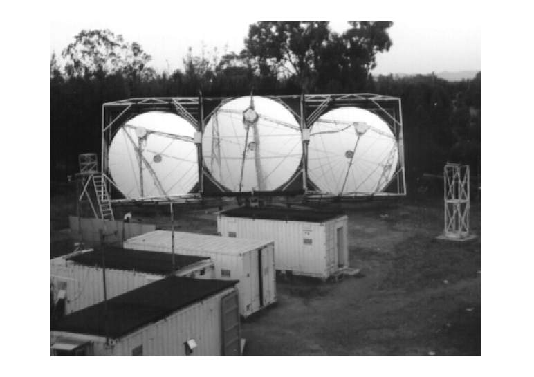
The Mark 6 telescope consists of three parabolic flux collectors mounted on a single alt-azimuth mount (see Figure 1). By operating a multiple reflector telescope and using fast coincidence techniques, it is possible, for a fixed (small) rate of accidental events, to run at a higher detector gain and so achieve a lower energy threshold than either of the other options (?, ?, ?, ?). Our previous experience has shown that a triple coincidence system is optimum for maximising the sensitivity and achieving a low energy threshold [Brazier et al. (1989)]. Further improvement may be added by requiring a spatial correlation between the three signals recorded in the three flux collectors in a narrow time window.
It is important to note that such a triple-mirror fast coincidence system removes the background due to the effects of local muons in the atmosphere and in the PMTs.
Another advantage of a triple coincidence system is that the two additional samples of Cerenkov light taken by two well-separated detectors strongly favour triggering by low energy gamma rays and allow additional proton rejection on the basis of fluctuation measures when analysing data in the higher energy region.
This paper describes in detail the design, construction and operation of the Durham University Mark 6 telescope. We also consider the basic performance characteristics of the Mark 6 telescope, and include the results of a preliminary investigation of the telescope’s energy threshold.
Section 2 Large Area Flux Collectors
2.1 Overview
The mirrors were designed be of adequate optical quality for use with imaging cameras (pixel resolution ), lightweight, of low cost and easy to produce in large numbers. A mirror focal length of and an aperture of f/1.0 has been specified to give an image scale compatible with a camera containing 91-elements of diameter and allow the effective use of light collecting cones employing no more than a single reflection. Our specification of mirror diameter, focal length and pixel size ensures that the image of a Čerenkov flash will not be distorted by the finite depth-of-field.
Ray tracing and measurements have confirmed that the off-axis performance of parabolic mirrors is adequate for our purposes. While segmented mirrors can be designed which have superior off-axis performance compared to an ideal parabolic mirror by reducing the effects of coma (e.g. the Davies-Cotton design employed by the Whipple 10 m telescope — see ?, ?), they have disadvantages for event triggering and energy threshold due to their non-isochronous performance.
2.2 Manufacture of Large Area Mirrors
The construction principle employed follows that used to produce the antenna sections for the UK millimetre-wave telescope by the staff of Rutherford Appleton Laboratory (J. Hall, private communication) and adapted by us to produce mirrors for a range of Čerenkov telescopes since 1985 (?, ?, ?, ?). For ease of manufacture, each mirror is made from 24 close fitting sectors. Each sector is filled with aluminium honeycomb material. To give rigidity, the back of the honeycomb is bonded to a dural backplate and surrounded by a dural frame. The front reflecting surface is a sheet of anodised aluminium which is vacuum formed onto a convex steel plug and bonded to the front surface of the honeycomb.
The aluminium honeycomb employed in our mirrors is Aeroweb 3003 which has a cell size of 0.8 cm and a foil thickness of 0.06 mm. The thickness of the honeycomb web is 50 mm. The adhesive used to bond the honeycomb to the front and back sheets is Redux 420A/B (Ciba-Geigy). The material used for the reflecting surface is Alanod 410G Special aluminium sheet, of thickness 0.5 mm, which is anodised during manufacture to give a specular reflection of over a wavelength range of 300 – 700 nm. The rear surface of the mirror is dural sheet of 1.6 mm thickness.
During manufacture the mirrors are cold cured for 24 hours to ensure a faithful reproduction of the shape of the plug. The mirrors formed using this technique are identical; the limit to quality is the form of the plug. After curing, the mirror segment is released from the plug and trimmed to shape. Any gaps in the rear surfaces of the mirrors are then filled with resin, and painted white to limit solar heating (which occurs when the telescope is parked with its rear to the sun).
The weight of each mirror sector is 14 kg and the material cost is £150. Manufacturing effort is technician hours per sector, excluding the fabrication of the plug.
Further improvements to these mirrors are possible by reskinning with a new Alanod reflective surface formed over a more accurate plug.
2.3 Characteristics of Mirrors
2.3.1 Reflectivity
The total reflectivity of the mirror surface material was measured to be over the wavelength range of interest to us () (T.C. Weekes, private communication; A.F. Vickers, private communication). Specular reflection is measured to be . The reflectivity of a sample of the front surface material was not significantly deteriorated by exposure to an industrially-polluted atmosphere over a period of 24 months. No significant deterioration in the mirrors of the Mark 3 telescope has been observed in over ten years’ exposure to the elements.
The requirement for accurate field alignment of three flux collectors, each comprising 24 of these large sectors, necessitated development of a new alignment procedure. A self contained, rotating laser system within a 4 m length of rigid aluminium channel was produced, which provided a system of parallel laser beams which could be swept over each mirror segment in turn, imitating the light from a distant light source. The spin axis of the laser system and the nominal optic axis of the flux collector were adjusted until they were coincident. The principal laser beam passed through the focus, which is at the centre of the detector package at the focal plane, and impinged on the centre of the flux collector. Once this condition was achieved the mirror sectors were adjusted successively to bring their individual foci to the collective focus of the flux collector.
2.3.2 Image Formation
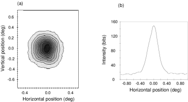
The success of the fabrication and alignment of the mirrors has been tested by focusing a stellar image onto the image plane and recording this image with a CCD camera. In Figure 2 we show the results of such a measurement. The RMS of the recorded image is . A cross-section through the image is also shown. The images formed by all three collectors are similar, and have remained stable over a period of 3 years.
Section 3 Telescope Mount and Steering
3.1 Alt-azimuth Mount
The support for the Mark 6 telescope is a purpose made alt-azimuth mount, the design of which has been influenced by those successfully employed in our earlier telescopes.
The three flux collectors are rigidly connected and are supported on a cradle by two bearings on a horizontal axis. The structure is approximately in balance at all zenith angles.
3.2 Telescope Steering/Pointing
The control of the attitude of the telescope is via DC servomotors driving onto gears mounted directly on the telescope structure. Both motors incorporate an integral gearbox, while the azimuth drive has a N m variable torque limiter to protect the motor and gearbox against damage caused by wind forces on the telescope. Angles are sensed by absolute digital 14-bit shaft encoders with a resolution of . The calculated azimuth and zenith of a source is compared by a digital servomechanism (employing 12-bit resolution) with the shaft encoder outputs at 100 ms intervals. The error signals are passed via DACs to the DC motor amplifiers. These provide damping on acceleration and stabilise the movements of the telescope structure. Thus although the telescope pointing is known to a resolution of , the source can be offset from the camera centre by up to by this mechanism. This offset is corrected for in the calculation of the image parameters used for gamma-ray selection (see ? ?, ?).
3.3 Direction Sensing/Measurement
The attitude of the telescope is measured in two ways. The shaft encoder positions are recorded for each event to 14-bit accuracy. This gives a measurement of the telescope’s pointing to within the telescope. In addition, a coaxial optical CCD camera (Santa Barbara Instrument Group ST-4 using a 50 mm lens) is mounted on the telescope and is used to absolutely calibrate the shaft encoders on a continuous basis. A typical integration time of 3 s is employed. The output of this CCD camera is continuously monitored by microcomputer, which measures the position and brightness of a nominated guide star within the field. This information is integrated into the data stream on an event-by-event basis. Guide stars of magnitude can be employed, providing absolute position sensing better than .
With a typical CCD star field the absolute pointing position of the telescope can be updated in a time of 3 s which can be compared with a typical event rate of 15 Hz. Full details of the extraction of the absolute position of the telescope will be presented elsewhere [Chadwick et al. (1998c)].
3.4 Pointing Accuracy
False source analysis has been shown to be a useful method of demonstrating that -ray like events originate from the source direction [Kifune et al. (1995)]. Conversely, such analyses may also be used to verify the steering performance of a telescope, if an established -ray emitter is observed.
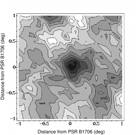
An analysis of events from PSR B1706-44 selected as -ray candidates has been made on the basis of shape alone [Chadwick et al. (1997b)], in which the position of the source has been assumed to be at a matrix of positions in the field of view of the Mark 6 telescope’s camera. For each false source position, the values of ALPHA for the events have been calculated and the selection criterion ALPHA applied. We show in Figure 3 a plot of the significance of the source detection as a function of assumed source position. The relative accuracy of the Mark 6 telescope pointing is found to be arcmin.
Section 4 Photodetectors
4.1 Overview
The Mark 6 telescope contains a camera consisting of 91 one inch diameter PMTs surrounded by a guard ring of 18 two inch diameter PMTs placed at the focus of the central flux collector. At the focus of each of the left and right flux collectors is a detector package consisting of 19 hexagonal PMTs (56 mm across the flats). All detector packages have flux concentrators fitted; in the case of the camera these are designed to increase the amount of light collected by the PMTs, whereas in the left and right triggering detectors the flux concentrators improve the temporal performance of the PMTs.
4.1.1 Hamamatsu R1924 Diameter Circular PMT
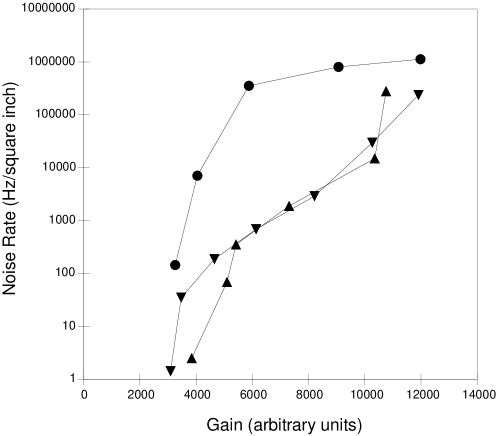
The performance of this tube is shown in Figure 4 where the noise rate (for events exceeding a 50 mV discrimination level after amplification) is plotted versus the gain. The choice of PMT for a high-resolution imaging camera was between this and the corresponding Burle tube (type S83062E); the choice was determined largely on the basis of ease of mechanical assembly, since the performance of the two PMTs was similar.
4.1.2 Phillips XP3422 55mm Hexagonal PMT
The Phillips XP3422 is an 8-stage hexagonal PMT, with 56 mm useful width across the flat sides and a bi-alkali photocathode. It has not been used previously in ground-based gamma-ray astronomy. It has a linear focussed dynode structure with CuBe dynodes. The nominal risetime (10% – 90%) of the tube is ns and the FWHM is ns, with a transit time of ns.
A potential limitation of PMTs with large area photocathodes is the dependence of transit time on the point of incidence of the photon on the photocathode. We have measured transit time relative to the response of a Hamamatsu PMT. The transit time for the Phillips XP3422 PMT is at least 12 ns greater than that for the PMT. Furthermore, the variation in transit time between photons arriving on the central axis and those arriving at the vertices of the PMT face is 10 ns. Although the nominal timing characteristics of this tube are worse than those of the 8575 diameter and R1924 diameter PMTs, the inevitable degradation of the signal when transmitted down m of cable from the telescope and the effect of the recording electronics limits the importance of this disadvantage. The temporal performance provides the motivation for the addition of flux concentrators to direct the Čerenkov light towards the centre of the photocathode. The flux concentrators are described in Section 4.2.
A subset of a large sample of these tubes has been found to have an unusually good ratio of the response to Čerenkov light to the noise — see Figure 4. Thus, although the inherent temporal response of these hexagonal tubes is relatively poor, the greatly improved noise performance and the use of light cones to enhance the temporal performance results in these tubes being useful for experiments aiming to detect low energy -rays.
4.2 Triggering detectors
The photodetectors of the left and right flux collectors each consist of 19 Phillips XP3422 hexagonal tubes and are primarily used as a part of the event selection system. The PMTs are arranged in a close packed hexagonal pattern (see Figure 5(b)). They are magnetically shielded and electrically insulated, and are mounted with their shielded hexagonal faces touching. The signal from the last dynode is taken from the detector package to the control room via 50 m of coaxial cable (type CT100). The applied voltages and gains of the PMTs are individually adjustable.
We have added light concentrators to improve the temporal respose of these PMTs. These are designed to concentrate the incident light on the central 44 mm diameter circle of the hexagonal photocathode, and are scaled-up versions of those developed for the PMTs. While employment of these light concentrators reduces the total amount of light detected by the PMT by a few per cent, the rise time of the signal reduces by 15% and, most importantly, the height of the signal increases by 15% corresponding to a decrease in threshold of a similar amount.
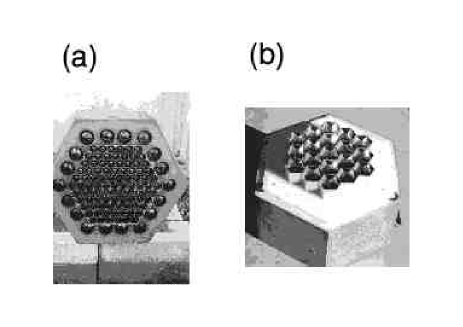
4.3 Camera Detectors
The detector package for the central collector of the camera consists of 91 circular Hamamatsu R1924 PMTs arranged in a close-packed hexagonal array, giving a pixel size of , and surrounded by 18 circular Burle 8575 PMTs which form a guard ring. The arrangement of tubes is shown in Figure 5(a). Since the dead area between the tubes amounts to 45%, we have constructed conical reflective light guides for these tubes resulting in a 70% increase in the detected light pulse.
Section 5 Telescope Trigger
The Mark 6 telescope uses a 3-fold spatial and 4-fold temporal coincidence system. The event selection for the Mark 6 telescope consists of two elements:
-
1.
The left/right flux collectors, each viewed by 19 hexagonal PMTs. An event selection is initiated whenever a signal is detected from a pair of PMTs at similar positions in the left/right detectors.
-
2.
The central flux collector. This is viewed by the ‘camera’, which includes 91 PMTs which cover a similar area of the sky as the left/right PMT matrices. For an event to be selected, it is required that any 2 of the 7 camera PMTs which cover the same area of sky as the left/right PMTs which have responded also produce a signal and that the 2 PMTs are adjacent.
In the Mark 6 telescope, selections 1 and 2 above are both achieved using a hardware first-level trigger with a decision time of ns (see Section 6.3). The discriminator threshold is set at 50 mV for all PMTs, the signals from which are first subject to amplification. The most sensitive element of the system at present is the central flux collector/camera combination; work on increasing the sensitivity of the left/right detectors continues.
Section 6 Electronic Systems
6.1 Overview
The design of the recording and control electronics for the Mark 6 telescope has followed the pattern developed for our previous telescopes. We separate the telescope performance monitoring and data logging functions, and employ a network of distributed computers to control and monitor the telescope’s performance and log the data.
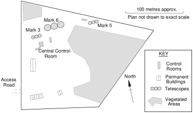
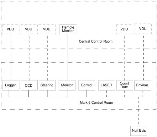
The Mark 6 telescope has been designed to be integrated into the Narrabri telescope environment, where it operates in conjunction with the existing telescopes. A schematic diagram of the telescope environment is shown in Figure 6. Each telescope has a self-contained control room adjacent to it, which houses the control and logging electronics and computers.
The central control room, from which the operation of all the telescopes can be monitored, is near the Mark 3 telescope. The individual telescopes’ control rooms and the central control room are connected by two local area networks (LANs), a medium bandwith LAN for control purposes and a high bandwidth LAN for data transfer. Each telescope passes performance information to a display computer in the central control room so that its operation can be continuously monitored. Also relayed to the central control room are the steering and logging computer displays, and the display from the paraxial CCD camera, so that telescope pointing and logging can be monitored.
A rubidium oscillator is used as the site-wide local time standard (see Section 6.4). The output from this oscillator is used by each telescope for timestamping the arrival of every Čerenkov flash. A microcomputer and associated electronics produce a randomly occurring trigger pulse which is distributed to all telescopes and mixed with their event trigger to provide a measure of the digitizers’ pedestals.
Event triggers from each telescope are passed via high bandwidth cable to the Mark 5 telescope control room, where TDCs are used to measure the arrival time differences between events which trigger two or more telescopes on the site.
6.2 Telescope Performance Monitoring System
The general performance and stability of the telescope is monitored by measuring the anode currents and single-fold rates from each of the 147 PMTs, 3-fold event rates, ancillary data (mirror, laser and camera temperatures, wind speed, etc.) and steering information. Anode currents are monitored by purpose-designed ADC units, while the single-fold rates are monitored using fast scalers. In addition, the ‘2-of-7’ rates from the central camera and the 3-fold coincidence rates from each of the 19 triggering channels are measured and displayed.
The ADCs and scalers are read out by a 32-bit RISC computer which, as well as displaying the measured anode currents and single-fold and coincidence rates, performs a series of checks that the various parameters are within predefined limits and will produce audible and visible warnings for the operator should any of the parameters fall outside these limits. A schematic diagram of the telescope performance monitoring system (TPMS) is shown in Figure 7.
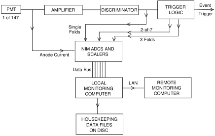
The telescope performance data are updated every 6 seconds, and this information is then broadcast over the local network to the corresponding remote monitoring computer in the central control room, which has an identical set of display and warning options. A limited subset of performance data is included in every event record; every minute, the complete performance data are recorded for subsequent off-line analysis.
6.3 Data Logging System
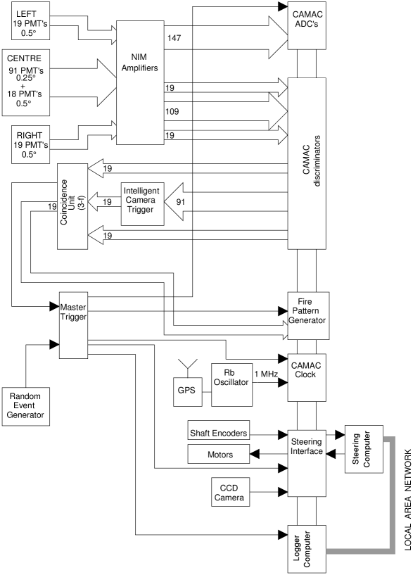
A schematic diagram of the data logging system employed in the Mark 6 telescope is shown in Figure 8. It is similar to that used in our previous telescopes [Brazier et al. (1989)].
The signal from each PMT is passed down 50 m of CT100 air-cored cable into the control room, where the signal transit time is trimmed using a short length of RG179 cable to allow for individual PMT transit time differences. The analogue signal then enters an automatic gain control (AGC) unit which performs a number of functions:
-
1.
the impedance of the signal path is changed from to for subsequent processing
-
2.
the anode current is sampled and converted to a voltage for subsequent monitoring
-
3.
the anode current may be compared with a preset value and an error signal is generated to drive an LED within the PMT’s field of view, so that the PMT can be run under constant illumination conditions, if so desired
-
4.
the analogue signal is AC coupled and output for subsequent processing.
The output from the AGC unit is passed to a fast amplifier (LeCroy Model 612A) where it is amplified by a factor of 10 and fanned out. One output from each channel is delayed by an appropriate amount and taken to the input of a fast charge digitizer (LeCroy Model 2249A). The second output from the amplifier is taken to the input of a fast discriminator (LeCroy Model 4413). An output from each of the discriminators is used for monitoring the noise rate of each PMT, while the other outputs are used to form coincidences between a pair of outputs from the left and right detectors and a corresponding response in the central camera. The coincidence system has been designed to be flexible so that various approaches to defining a camera trigger can be employed. The resulting left, right and camera signals are passed to 3-fold coincidence units (LeCroy Model 4516), with an effective coincidence resolving time of ns.
The Mark 6 telescope is normally operated in a mode where the central camera response is defined to occur when any two adjacent members of a group of seven PMTs (which view the same area of sky as an individual left/right camera PMTs) have passed a preset discrimination level. This coincidence requirement is implemented in hardware, using a purpose-designed module employing ECL logic. The resolving time for this ‘2-of-7’ circuit is less than 10 ns.
Individual ECL outputs from the logic unit, corresponding to a trigger in any of the 19 ‘3-fold’ channels, are taken to a ‘coincidence register’, where the telescope ‘fire pattern’ is latched for subsequent recording. All event rates are scaled and recorded.
The OR’ed outputs from each section of the logic units are stretched and taken to a voter coincidence unit where they are mixed with the pedestal triggers to form a master trigger for the telescope. This master trigger is then fanned out to provide (in the correct time sequence):
-
1.
an interrupt to signal an event to the logging computer
-
2.
signals to latch the coincidence registers, the telescope steering information (both from the shaft encoders and the CCD star tracker) and the event time
-
3.
gate pulses for the fast charge digitizers
-
4.
a signal for inter-telescope timing purposes.
In addition, the logger system can record a limited amount of information (event time and telescope ‘fire pattern’) for events occurring within the readout time of a preceding event.
The network of computers employed to control and monitor the Mark 6 telescope is shown in Figure 9.
The logging computer is a 32-bit RISC computer, which communicates with the CAMAC electronics via HyTec Model 1330 CAMAC interfaces. The logger is interrupt driven and has a deadtime of 2.3 ms (essentially limited by the readout time of the CAMAC crates). 0.5 kbyte of data is collected per event and data are recorded on a local 2 Gb hard disk for subsequent archiving.
The performance of the telescope is monitored using a 32-bit RISC computer (see Section 6.2), which broadcasts the monitoring information to the central control room. The CCD star tracker is also controlled by a 32-bit RISC processor (see Section 3.3). The system used for steering the telescope is described in Section 3.2; it employs an 8-bit microcomputer using a system common to all telescopes.
All the computers operating the Mark 6 telescope communicate via a LAN and all operator interaction during normal operation is via a single controlling computer, which supervises all the tasks associated with observing, including passing target coordinates to the steering computer and commanding the steering computer to commence tracking the object and controlling the logger and monitor computers.
6.4 Timekeeping
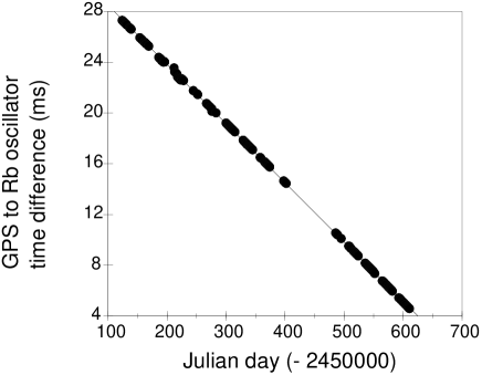
A rubidium atomic oscillator provides a frequency standard for the whole of the Narrabri site. We employ an Efratom Model FRK-L Rb oscillator, which provides a stable 10 MHz reference signal. The drift rate is regularly monitored and measured by comparison with the signal from a GPS receiver. This provides a daily absolute comparison with our local time standard. All events are time stamped to a relative accuracy of and with an absolute accuracy of . In Figure 10 we show the measured drift rate of the Rb oscillator relative to GPS-derived time over a period of 1 year.
Section 7 Calibration
In order to measure accurately the images from such a telescope it is necessary to know the gains of each PMT, so that the digitized output can be accurately related to the observed Čerenkov photon density.
7.1 Absolute Calibration
Calibration of the PMTs and electronic channels is performed initially by the use of a radioactive light pulser. This consists of dispersed in a small piece of plastic scintillator, and produces an optical flash of ns duration at a rate of about 1 kHz. The light pulser is placed at a fixed distance from the front face of each PMT in turn (in complete darkness) and the pulse area spectrum produced is recorded. Knowledge of the pulse area spectrum of each tube and the emission characteristics of the light pulser enable the absolute gains of the tubes to be calculated.
The light output of the pulser is, according to the manufacturers’ specifications, 300 photons per pulse. Independent measurements indicate an output of 70 7 photoelectrons per pulse, depending on the quantum efficiency of the PMT responsible for the measurement.
7.2 Relative Calibration
The absolute gain measurement method described above suffers from two disadvantages:-
-
1.
the amount of light emitted by the light pulser is so small that the calibration can only be done with the PMT in the dark for the signal to be detected above the noise
-
2.
calibration cannot be performed continuously throughout an observation.
To circumvent these problems, a method has been developed using a nitrogen laser to provide a diffuse source of blue light from a plastic scintillator. By arranging for the telescope to be triggered by a flash of laser induced light, gain calibration measurements can be incorporated directly into the datastream and the telescope triggering monitored. However, relative gain calibration only is possible, since the number of photons emitted per laser flash varies and depends on, for example, the laser temperature.
The 3 ns, 40 kW pulse of 337 nm radiation from a nitrogen laser (VSL Model 33700) impinges on a 5 cm cube of plastic scintillator (NE102), which converts the laser pulse to a pulse of radiation. This blue light is transmitted by means by plastic fibre optic cables to the centre of each of the three mirrors. There is little dispersion suffered by the pulse along the 20 m of fibre optic cable. The output from the fibre optic cable at the centre of each mirror is diffused using a flashed opal diffuser, producing a pulse of light which is uniform over the face of the detector package.
The lengths of the left, right and centre fibre optic cables are trimmed to enable the respective calibration pulses to trigger the telescope. A single PMT is placed in a collimator next to the camera such that it views only the light pulse produced by the laser and is shielded from light reflected off the mirror. Signals from this PMT then provide a simple means of reliably identifying and monitoring the calibration pulses, which are recorded in an identical manner to real events. The laser produces individual pulses separated by random intervals with a mean rate of 50 min-1 maintained throughout observations. This procedure allows the PMT gain to be measured to 1 – 2% for each 15 minute data segment.
7.3 Stability of Response
7.3.1 Introduction
The Mark 6 telescope is equipped with comprehensive monitoring equipment. Throughout observations, the performance of the PMTs is measured. The PMTs’ anode currents and noise rates are recorded using the TPMS and their relative gains are measured. In addition, we monitor environmental conditions such as wind speed, atmospheric pressure, air temperature and the temperatures inside the detector packages and laser system.
7.3.2 Temperature Effects on PMTs
Continuous monitoring of the performance of the Mark 6 PMTs during observations have shown that their gains are affected by temperature variations. Tests under controlled laboratory conditions confirm that the gains of the PMTs typically fall by up to for the Phillips XP3422 and for the Hamamatsu R1924 for every C rise. Power dissipated in the PMT dynode chains means that the temperature in the camera rises above ambient in the first hour of an observation, with a consequent change in PMT performance. To ensure PMT stability throughout observations, all three detectors on the Mark 6 Telescope are equipped with temperature control systems. Heaters in the detectors raise their internal temperatures before observations begin, and thereafter their temperatures are thermostatically controlled. The increase in PMT noise that this produces is small compared with night sky noise.
7.3.3 Geomagnetic Effects
The PMTs used in the Mark 6 telescope are equipped with mu-metal shielding. This has been shown to protect them from the effects of the earth’s magnetic field in laboratory and field tests. The change in gain for a 0.5 gauss change in magnetic field is for a bare tube; for a tube shielded with mu-metal we have been unable to measure an effect.
7.3.4 Laser Stability
Monitoring the laser from which we derive the relative gain calibration pulses for the Mark 6 telescope suggested that the size of the laser pulse not only varied from pulse to pulse but also changed systematically with temperature. Measurements made in the laboratory confirmed this was the case; the height of the pulse from the laser decreases by less than per ∘C increase. The temperature of the laser is measured routinely during telescope operation.
Section 8 Performance of the Telescope
The Mark 6 telescope has been operational since March 1995 and the performance is summarized below.
8.1 Response of Telescope
8.1.1 Cosmic Ray Count Rate
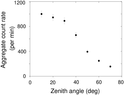
Count rates of up to 1000 per minute from a field of view of 9 square degrees have been achieved with the Mark 6 telescope pointed near the zenith. Figure 11 shows the variation of the count rate with zenith angle. The measured zenith angle distribution is typical of that observed with a multiple-mirror telescope system — the Mark 6 trigger is dominated by the medium-resolution left/right cameras.
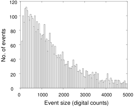
8.1.2 Event Size Distribution
The distribution of Čerenkov light flashes with event sizes expressed in terms of digital counts is shown in Figure 12 (200 digital counts is equivalent to 125 GeV of energy for a -ray event).
8.1.3 Typical High Resolution Images
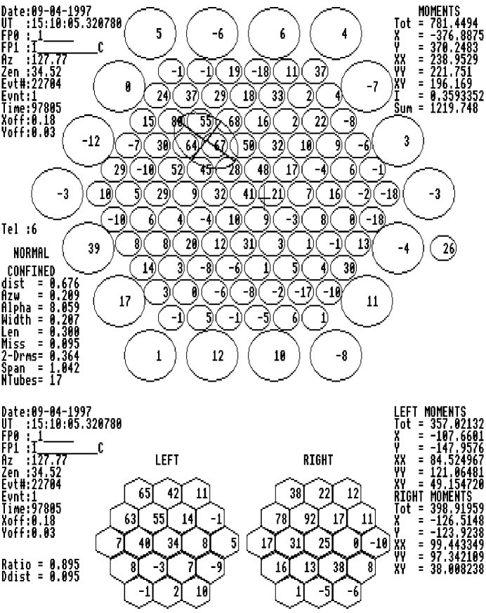
In Figure 13 we show some typical data recorded with the Mark 6 telescope. The response of each PMT in the camera has been adjusted to allow for variations in digitizer pedestal and PMT gain. Initial analysis of the camera images has followed the procedure adopted by the Whipple collaboration [Fegan et al. (1994)]. Each PMT response is labelled as (i) an ‘image’ PMT corresponding to a signal of at least 37.5% of the peak pixel, (ii) a ‘border’ PMT corresponding to a signal of at least 17.5% of the peak pixel if it is next to an ‘image’ tube or (iii) neither of these when the response is set to zero. Categories (i) and (ii) are used to calculate the shape parameters [Hillas (1985)] which describe the shape and orientation of the detected image.
8.1.4 The Responses of the Triggering Detectors
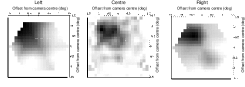
In addition to the high-resolution camera image, a 19-tube image is obtained from each of the left and right detectors. This arrangement is central to achieving a stable and low energy threshold. These detectors also provide additional information on the Čerenkov light and further background rejection criteria. In Figure 14 we show the effect of interpolation and reducing to a common display the data for the 3 imaging systems.
8.1.5 Background Rejection Using Data from the Triggering Detectors
Simulations suggest that the characteristic distance for fluctuations in the Čerenkov light produced by a primary cosmic ray proton is about 15 m. The lateral distribution of Čerenkov light from a VHE -ray is much smoother than this. The triggering detectors on the Mark 6 telescope are 15 m apart. Measurements of the fluctuations in the Čerenkov light from a shower made over this baseline can therefore be used as a method of rejecting hadronic showers. Two simple measures of fluctuation have been considered. The first is the ratio of the size of the smaller to the larger of two light samples detected (LRR). The size of the left and right samples are obtained by summing the responses of each of the 19 pixels in each camera. It was expected that -ray shower images should have values of LRR close to unity. Simulations and results from observations agree that this quantity does not produce a very efficient criterion for rejecting background events. More effective is the angular distance between the centroids of the two images (). Simulations indicate that selecting small values of produces a selection with a Q factor of 1.4. This parameter has been used as part of the routine analysis and appears to be as successful as the simulations suggested [Chadwick et al. (1997a)].
8.2 Energy Threshold
The estimation of the energy threshold for the detection of gamma rays by an atmospheric Čerenkov telescope is a difficult task [Kohler et al. (1996)]. The following is a preliminary approach to the problem of estimating the energy threshold of the Mark 6 telescope.
Monte Carlo simulations of the photon yield from hadronic air showers have been generated using the MOCCA program [Hillas (1982)]. 40000 cosmic rays were generated from a circular field of view in radius and out to a maximum impact parameter of 250 m. The simulations were performed for a telescope inclined at to the zenith. These were then presented to a model of the Mark 6 telescope, and by altering the discriminator thresholds of the telescope model, the trigger rate for the simulations was matched to the measured cosmic ray count rate. Ideally, the telescope model should be further validated by also matching the parameter distributions observed, but the preliminary investigation described here has not included this.
This model of telescope performance was then applied to results from Monte Carlo simulations of gamma ray air showers in order to estimate the expected threshold energy for the detection of photons. 50000 gamma ray showers were generated with energies ranging from 100 to GeV for a source with a power law spectrum of index . This is the same as the measured value of the differential spectral index of the Crab nebula in the VHE range [Vacanti et al. (1991)].
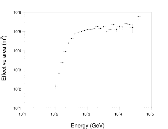
The effective detection area for a ground-based atmospheric Čerenkov telescope depends on the gamma ray energy, altitude, the Čerenkov light pool size and the triggering probability. Figure 15 shows the effective detection area for the Mark 6 telescope as a function of energy for gamma rays from a point source.
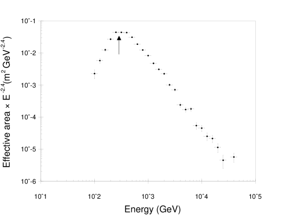
The threshold energy of such an atmospheric Čerenkov telescope may be defined in many ways. Here we use the energy at which the differential gamma ray flux is a maximum. This is illustrated in Figure 16, which predicts a threshold energy for gamma rays of GeV. There are many potential sources of error in this estimate of energy threshold. For instance, the values of spectral index, trigger conditions and mirror reflectivity applied will all introduce uncertainties. Consequently, the systematic error in the determination of the energy threshold is conservatively estimated as . It should also be noted that the values derived here are the threshold energy and mean effective area assuming 100% gamma ray retention. Any background discrimination technique inevitably also rejects a fraction of the gamma ray signal, altering the energy threshold and effective area for gamma ray detection.
Section 9 Verification of Performance
The performance of the Mark 6 telescope has been verified using data from observations of PSR B1706-44 [Chadwick et al. (1997b)] and Cen X-3 [Chadwick et al. (1998b)]. These have shown that, for events corresponding to -ray energy GeV, conventional imaging techniques enhance the -ray signal and provide a detection from 10 hours of data, after rejection of of background protons and retention of of the -rays. For our observations of PSR B1706-44 we find a Q-factor of . The -ray source is located to an accuracy of 5 arcminutes.
Section 10 Conclusions
A new large VHE gamma ray telescope (the University of Durham Mark 6 telescope) was deployed on the Narrabri site in July 1994 and has collected data since March 1995. In its present configuration, the telescope has a gamma ray energy threshold of 150 GeV. Further reductions in the energy threshold will be possible.
The telescope is equipped with a 109-element camera in the central flux collector. Imaging can provide effective discrimination between gamma-ray and hadron initiated events for gamma ray energies above 300 GeV.
Other papers in preparation will address the analysis techniques applied to the Mark 6 telescope data, including the use of the information from the left and right detectors and the low energy performance of the telescope.
Acknowledgements
This work was funded by the U.K. Particle Physics and Astronomy Research Council. We are grateful to the University of Sydney for the lease of the site at Narrabri. The assistance of the staff of the Main Workshop, the Student Workshop and the Electronics Workshop of the Physics Department, University of Durham, in the construction of the Mark 6 telescope is gratefully acknowledged.
References
- Bowden et al. (1993) Bowden, C.C.G., Bradbury, S.M., Chadwick, P.M., Cottle, P., Dickinson, J.E., Dipper, N.A., Dye, S., Hilton, S.E., Hogg, W., Lincoln, E.W., McComb, T.J.L., Orford, K.J., Osborne, J.L., Parkin, K., Rayner, S.M., Robertshaw, M., Roff, D.G., Tindale, K. and Turver, K.E.: 1993, in R.C. Lamb (ed.), Towards a Major Atmospheric Cherenkov Detector - II, Iowa State University: Ames, pp. 230–234.
- Brazier et al. (1989) Brazier, K.T., Carramiñana, A., Chadwick, P.M., Currell, T.R., Dipper, N.A., Lincoln, E.W., Mannings, V.G., McComb, T.J.L., Orford, K.J., Rayner, S.M. and Turver, K.E.: 1989, Exp. Astron., 1, 77–99.
- Cawley et al. (1990) Cawley, M.F., Fegan, D.J., Harris, K., Hillas, A.M., Kwok, P.W., Lamb, R.C., Lang, M.J., Lewis, D.A., Macomb, D., Reynolds, P.T., Schmid, D.J., Vacanti, G. and Weekes, T.C.: 1990, Exp. Astron., 1, 173–193.
- Chadwick et al. (1990) Chadwick, P.M., McComb, T.J.L. and Turver, K.E.: 1990, J. Phys. G. Nucl. Particle Phys., 16, 1773–1803.
- Chadwick et al. (1997a) Chadwick, P.M., Dickinson, M.R., Dipper, N.A., Holder, J., Kendall, T.K., McComb, T.J.L, Orford, K.J., Osborne, J.L, Rayner, S.M., Roberts, I.D., Shaw, S.E. and Turver, K.E.: 1997a, Towards a Major Atmospheric Cerenkov Detector V, in the press.
- Chadwick et al. (1997b) Chadwick, P.M., Dickinson, M.R., Dipper, N.A., Holder, J., Kendall, T.K., McComb, T.J.L, Orford, K.J., Osborne, J.L, Rayner, S.M., Roberts, I.D., Shaw, S.E. and Turver, K.E.: 1997b, Proc. 25th. Int. Conf. Cosmic Rays, 4, 189–192.
- Chadwick et al. (1998a) Chadwick, P.M., Dickinson, M.R., Dipper, N.A., Holder, J., Kendall, T.K., McComb, T.J.L, Orford, K.J., Osborne, J.L, Rayner, S.M., Roberts, I.D., Shaw, S.E. and Turver, K.E.: 1998a, Astroparticle Phys., submitted.
- Chadwick et al. (1998b) Chadwick, P.M., Dickinson, M.R., Dipper, N.A., Kendall, T.K., McComb, T.J.L, Orford, K.J., Osborne, J.L, Rayner, S.M., Roberts, I.D., Shaw, S.E. and Turver, K.E.: 1998b, Astrophys. J., in the press.
- Chadwick et al. (1998c) Chadwick, P.M., Dipper, N.A., Lyons, K., McComb, T.J.L, Orford, K.J., Osborne, J.L, Rayner, S.M., Shaw, S.E. and Turver, K.E.: 1998c, in preparation.
- Cronin et al. (1993) Cronin, J.W., Gibbs, K.G. and Weekes, T.C.: 1993, Ann. Rev. Nucl. Part. Sci. 43, 883–925.
- Fegan (1997) Fegan, D.J.: 1997, J. Phys. G. Nucl. Particle Phys., 23, 1013–1060.
- Fegan et al. (1994) Fegan, D.J., Akerlof, C.W., Breslin, A.C., Buckley, J.H., Cawley, M.F., Chantell, M., Connaughton, V., Fennell, S., Gaidos, J.A., Hagan, J., Hillas, A.M., Kerrick, A.D., Lamb, R.C., Lessard, R.W., Lewis, D.A., McEnery, J., Meyer, D.I., Mohanty, G., Punch, M., Quinn, J., Reynolds, P.T., Rovero, A.C., Rose, H.J., Schubnell, M.S., Sembroski, G., Urban, M., Weekes, T.C., West, M., Wilson, C. and Zweerink, J.: 1994, in T. Kifune (ed.), Towards a Major Atmospheric Cherenkov Detector III, Universal Academy Press: Tokyo, pp. 149–162.
- Gibson et al. (1982) Gibson A.I., Harrison, A.B., Kirkman, I.W., Lotts, A.P., Macrae, J.H., Orford, K.J., Turver, K.E. and Walmsey, M.: 1982, Nature, 296, 883–835.
- Hillas (1982) Hillas, A.M.: 1982, J. Phys. G. Nucl. Particle Phys., 8, 1475–1492.
- Hillas (1985) Hillas, A.M.: 1985, Proc. 19th. Int. Cosmic Ray Conf., 3, 445–448.
- Kifune et al. (1995) Kifune, T., Tanimori, T., Ogio, S., Tamura, T., Fujii, H., Fujimoto, M., Hara, T., Hayashida, N., Kabe, S., Kakimoto, F., Matsubara, Y., Mizumoto, Y., Muraki, Y., Suda, T., Teshima, M., Tsukagoshi, T., Watase, Y., Yoshikoshi, T., Edwards, P.G., Patterson, J.R., Roberts, M.D., Rowell, G.P. and Thornton, G.J.: 1995, Astrophys. J., 438, L91–L94.
- Kohler et al. (1996) Kohler, C., Hermann, G., Hofmann, W., Konopelko, A. and Plyasheshnikov, A.: 1996, Astroparticle Phys., 6, 77–85.
- Lewis (1990) Lewis, D.A.: 1990, Exp. Astron., 1, 213–226.
- Patterson and Hillas (1989) Patterson, J.R. and Hillas, A.M.: 1989, Nucl. Inst. Meth. Phys. Res., A278, 553–564.
- Reynolds et al. (1993) Reynolds, P.T., Akerlof, C.W., Cawley, M.F., Chantell, M., Fegan, D.J., Hillas, A.M., Lamb, R.C., Lang, M.J., Lawrence, M.A., Lewis, D.A., Macomb, D., Meyer, D.I., Mohanty, G., O’Flaherty, K.S., Punch, M., Schubnell, M.S., Vacanti, G., Weekes, T.C., and Whitaker, T.: 1993, Astrophys. J., 404, 206–218.
- Schubnell et al. (1996) Schubnell, M.S., Akerlof, C.W., Biller, S., Buckley, J., Carter-Lewis, D.A., Cawley, M.F., Chantell, M., Connaughton, V., Fegan, D.J., Fennell, S., Gaidos, J.A., Hillas, A.M., Kerrick, A.D., Lamb, R.C., Lang, M.J., Meyer, D.I., Mohanty, G., Rose, J., Rovero, A.C., Sembroski, G., Weekes, T.C., Wilson, C. and Zweerink, J.: 1996, Astrophys. J., 460, 644–650.
- Turver and Weekes (1978) Turver, K.E. and Weekes, T.C.: 1978, Nouvo Cim., 45B, 99–107.
- Vacanti et al. (1991) Vacanti, G., Cawley, M.F., Colombo, E., Fegan, D.J., Hillas, A.M., Kwok, P.W., Lamb, R.C., Lang, M.J., Lewis, D.A., Macomb, D., O’Flaherty, K.S., Reynolds, P.T. and Weekes, T.C.: 1991, Astrophys. J., 377, 467–479.
- Weekes et al. (1989) Weekes, T.C., Cawley, M.F., Fegan, D.J., Gibbs, K.G., Hillas, A.M., Kwok, P.W., Lamb, R.C., Lewis, D.A., Macomb, D., Porter, N.A., Reynolds, P.T. and Vacanti, G.: 1989, Astrophys. J., 342, 379–395.