Warps and Secondary Infall
Abstract
Secondary infall in galaxies could cause the angular momentum of the outer halo to change its orientation. The generation of warps due to this effect is studied using N-body simulations.
Kapteyn Astronomical Institute, Groningen
Canadian Institute for Theoretical Astrophysics, Toronto
1. Introduction
In many spiral galaxies the outer regions of the disk curve away from the symmetry plane of the inner disk, resembling an integral sign. This is called a warp. The cause of this phenomenon is still uncertain, but a dark halo may play an important role. Sparke & Casertano (1988) found some long-lived warping normal modes inside an oblate halo potential, but they used a halo that was unperturbed by the disk. Later, Dubinski & Kuijken (1995) and Nelson & Tremaine (1995), following a comment by Toomre (1983), showed that when the response of the halo is taken into account the Sparke & Casertano modes are no longer long-lived.
Cosmic infall of matter onto galaxies has been proposed as a possible explanation for the warp phenomenon (Ostriker & Binney 1989). This infall likely causes the net angular momentum vectors of disk galaxies to reorient each Hubble time.
In this work, we simulate and analyze the response of a disk embedded in a halo whose orientation is changed slowly. The properties of the warps generated this way are studied later, both in shape and amplitude.
2. Simulation details
2.1. Construction of the Halo - Disk models
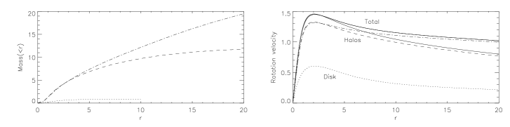
The halo and the disk have been constructed following Kuijken & Dubinski (1995), using a self-consistent approach. The halo has a lowered Evans distribution function, and the disk is modeled with concentric spinning rings. The mass profile and rotation curves of the different models can be seen in figure [1]. The main parameters of both models are summarized in table [1].
The number of particles used for each model was of particles for the halo, and 400 rings, each of them consisting of 90 particles.
| Disk | Halo | |||||||||
| Model | ||||||||||
| (1) | (2) | (3) | (4) | (5) | (6) | (7) | (8) | (9) | (10) | |
| C | 0.867 | 1 | 8 | 0.1 | 0.5 | -6.0 | 1.32 | 0.9 | 0.1 | 0.8 |
| D | 0.867 | 1 | 8 | 0.1 | 0.5 | -7.0 | 1.30 | 0.9 | 0.1 | 0.8 |
2.2. Code used to evolve the system
The N-body code use to evolve the system uses a hybrid approach: the halo is made of particles, and its effect is computed with a Self-Consistent Field code (Hernquist & Ostriker, 1992), expanding the potential in terms of some basic functions. The disk, however, is modeled using pivoted spinning rings. The dynamics on the disk are computed calculating the potential and acceleration on the “ring-particles”, and then these are used to calculate the torque on each ring. This is accomplished with a tree code (Barnes & Hut, 1986).
3. Results
The first approach to the problem was to consider a rigidly rotating halo, unaffected by the gravitational effect of the disk. The slewing rate of the halo was chosen to be H0 (100 km/s/Mpc for a disk scale length of 3.5 kpc), so that the angular momentum of the halo re-orients in the predicted timescale.The axis of rotation of the halo lies in the initial halo-symmetry plane.
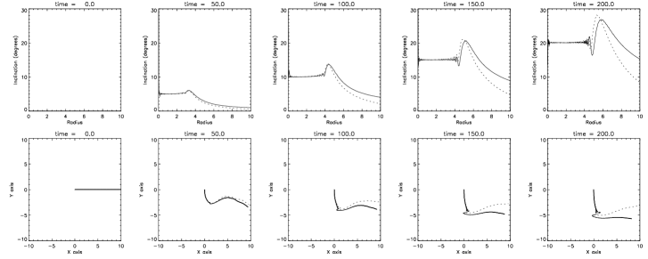
The results of the simulations for models C and D are shown in figure [2]. Here the inclination of the rings and the position angle of the line of nodes is plotted for different timesteps.
These plots show that the disk reorientation process is fast enough to follow the halo in the inner parts. The disk warps where its self-gravitation is not enough to hold it in the same plane. This is in perfect agreement with the Briggs law (Briggs, 1990): straight line of nodes in the center, leading spiral further out. If the mass of the disk is doubled, the region aligned with the symmetry plane of the halo increases (approximately one scale length), as expected.
4. Next
As mentioned in the introduction, the assumption of a non-responding halo is very simplistic. The next step is to simulate the re-orientation of a responsive halo that cosmic infall would cause. To do this we will put a rotating tidal field through the galaxy. This will make the symmetry plane of the outer halo change, gaining angular momentum
This will be done by placing 2 satellites symmetrically, so that the monopole term of the tidal field is zero, avoiding relative movements of the galaxy with respect to the satellites. This will also provide information about the influence of satellites on disks.
References
Barnes, J., Hut, P., 1986, Nature, 324, 446
Briggs, F.,1990, ApJ, 352, 15
Dubinski, J., Kuijken, K., 1995, ApJ, 442, 492
Hernquist, L., Ostriker, J. P., 1992, ApJ, 376, 375
Kuijken, K., Dubinski, J., 1995, MNRAS, 277, 1341
Nelson, R. W., Tremaine, S., 1995, MNRAS, 275, 897
Ostriker, E. C., Binney, J. J., 1989, MNRAS, 237, 785
Sparke, L. S., Casertano, S., 1988, MNRAS, 234, 837
Toomre, A., 1983, IAU Symp. 100, Internal Kinematics & Dynamics of Galaxies, ed. E. Athanassoula, pp. 177-86. Dordrecht: Reidel