Wide-field CCD imaging at CFHT: the MOCAM example
Abstract
We describe a new 40964096 pixel CCD mosaic camera (MOCAM) available at the prime focus of the Canada-France-Hawaii Telescope (CFHT). The camera is a mosaic of four Loral frontside-illuminated CCDs with 15 m pixels, providing a field of view of at a scale of 021 pixel-1. MOCAM is equipped with B, V, R and I filters and has demonstrated image quality of 05–06 FWHM over the entire field. MOCAM will also be used with the CFHT adaptive optic bonnette and will provide a field of view of 90′′ at a scale of 002 pixel-1. MOCAM works within the CFHT Pegasus software environment and observers familiar with this system require no additional training to use this camera effectively. The technical details, the performance and the first images obtained on the telescope with MOCAM are presented. In particular, we discuss some important improvements with respect to the standard single-CCD FOCAM camera, such as multi-output parallel readout and dynamic anti-blooming. We also discuss critical technical issues concerning future wide-field imaging facilities at the CFHT prime focus in light of our experience with MOCAM and our recent experience with the even larger UH 81928192 pixel CCD mosaic camera.
Laboratoire d’Astrophysique de Toulouse Observatoire Midi-Pyrénées, 14 Av. E. Belin, 31400 Toulouse, France
Dominion Astrophysical Observatory, 5071 West Saanich road, Victoria, B.C., V8X4M6, Canada
and
Institute for Astronomy, University of Hawaii, 2680 Woodlawn Drive, Honolulu, Hawaii 96822
Subject headings: instrumentation: CCD camera, data reduction, observational techniques
1 Introduction
With the coming of the new generation of giant telescopes, most 4-m class telescopes must identify observational programs where they will be the most competitive. Obviously, the outstanding image quality of the prime focus Canada-France-Hawaii Telescope over a one square degree field makes this telescope well suited for scientific programs requiring wide-field imaging with good spatial resolution. In fact, for some time there has been a general consensus that wide-field imaging should be developed at CFHT (Crampton 1992) and the recent work on weak gravitational lensing (Fahlman et al. 1994, Bonnet et al. 1994, Bonnet & Mellier 1995), and on the detection of dark halos and dust in edge-on nearby galaxies (Lequeux & Guélin 1996a, Cuillandre et al. 1996) have clearly demonstrated the unique capabilities of this telescope for high quality imaging over large fields. Strong scientific interests ranging from solar system studies to cosmology have been emphasized: e.g., detection of faint comets and Kuiper belt objects, photometry and astrometry in clusters and of stars in the galactic disk, statistical analyses of faint galaxy populations (galaxy-galaxy correlation function, galaxy-galaxy lensing, luminosity function of faint galaxies, weak lensing by clusters, superclusters and large scale structure), and multicolor photometry of faint quasars.
Wide-field imaging with subarcsecond seeing requires large CCDs capable of simultaneously covering a large field of view and adequately sampling the stellar point spread function. In addition to being physically large, with large numbers of pixels, the required CCDs should be of scientific quality, with high sensitivity, low readout noise, excellent charge transfer properties and good cosmetic quality. Moreover, the arrays must be mechanically flat and stable. From this point of view, very large monolithic arrays are potentially attractive detectors. Such devices, like the four output Loral 9K9K 8.75 m pixel CCD (Bredthauer 1995), already exist and may be a promising approach, particularly with the use of new microelectronic technologies which permit single output readout at very high speed and very low noise level (e.g. Luppino et al. 1995). At the present time, however, there exist no large monolithic devices (thinned or unthinned) capable of covering fields as large as the CFHT prime focus (1o field or 300 mm), and such devices are not expected to appear in the near future. Mosaicing the CCDs in a large focal plane is then a natural strategy to cover the wide field offered by the telescope. The detection of baryonic dark matter in galaxy halos was the first program to benefit from large mosaics: the MACHO project (Stubbs et al. 1993) uses a dual 4K4K camera, and the EROS project (Arnaud et al. 1994) uses a 3K1K mosaic. There are now several developments of large CCD mosaics already completed or still underway (see Luppino et al. 1994 for a recent review). The University of Hawaii 8K8K mosaic, in operation at CFHT and UH 2.2m since Spring 1995, is the largest astronomical CCD camera built to date (Metzger et al. 1996). However, the frontside-illuminated CCDs limit the sensitivity of these cameras, particularly in the blue, and the thinning of large devices is still a technical challenge despite many attempts using various approaches. But now, 2K4K thinned CCDs with m pixels are proposed by several builders. Future projects for wide-field imaging like the 8K10K thinned mosaic (CFH10K), and the further development of a 16K16K thinned mosaic which will cover the whole field of the CFHT prime focus (Vigroux 1995) will take advantages of these rapid developments.
The MOCAM project received strong support at the third CFHT users meeting in 1992 (Crampton 1992). A consortium was set up involving the Dominion Astrophysical Observatory (DAO), the Institut des Sciences de l’Univers (INSU), the Observatoire de Toulouse (OMP) and the University of Hawaii (UH), with additional help from CFHT. The camera was inspired by the early UH4K mosaic camera (Luppino & Miller 1992) with strong emphasis on low cost and rapid construction that would result in an easy-to-use, wide-field CCD camera for the astronomical community at CFHT. It was agreed with the CFHT executive that MOCAM should be delivered as a full CFHT instrument compatible with the CFHT Pegasus software interface environment (Christian et al. 1989). MOCAM was actually only the first step towards the development of larger mosaics for CFHT. In this respect, in addition to the strong scientific cases that motivated its development, MOCAM permitted the analysis of many of the technical and observational issues of wide-field imaging at CFHT.
This paper presents the MOCAM mosaic camera and some important issues relevant for the future of wide-field imaging at CFHT. Section 2 gives a complete overview of the technical design and the performance of MOCAM in the CFHT environment. Some details about image quality, blooming and data handling are also presented to provide practical information for CFHT users. Section 3 discusses some aspects of wide-field imaging from our experience with MOCAM and the UH8K. This section addresses important issues such as field distortion, scattered light, etc., which become important when imaging very large fields. We also point out various improvements needed at the CFHT prime focus for it to accommodate even larger arrays in the future.
2 MOCAM: a 4K4K MOsaic CAMera
Since the UH 4K4K camera (Luppino & Miller 1992) was designed for the CFHT prime focus, it was decided to simply duplicate the dewar and camera head, as well as the Loral 2K2K two-edge buttable CCDs initially used in this camera. The standard CFHT GenIII CCD acquisition system based on a San Diego State University (SDSU) controller (Leach 1988) was adapted by the Toulouse group to a parallel multi-output system, and the Pegasus software was upgraded to allow the acquisition of images as large as 33 Mbytes with the multi-output feature. The mechanical interface between the dewar and the prime focus bonnette which handles a five position filter wheel and a large iris shutter was designed and built at DAO. The whole camera was fully tested and optimized in Toulouse before shipment to CFHT for the successful November 1994 first light on the telescope.
2.1 CCDs and Dewar
The CCDs designed by J. Geary (Smithsonian Astronomical Observatory) were produced by the Loral Fairchild Imaging Sensor company (Geary et al. 1990). These thick 20482048, 15 m square pixel, two-edge-buttable CCDs have two low-noise outputs with a single serial register than can be split in two. These CCDs are fabricated on 100 mm wafers and have been laid out on the wafer with mirror symmetry, each wafer providing two left-hand CCDs and two right-hand CCDs. The mosaic is assembled from four CCDs such that all columns are oriented vertically, with the upper two devices having their serial registers at the top edge and the lower two devices with serial registers on their bottom edge. The mosaic then, must be assembled from two left-hand and two right-hand devices. Each Loral foundry run produced twenty wafers and, after three attempts, one run delivered several high quality CCDs with a yield of about 20%. The CCDs have a MPP boron implant under a parallel phase and allow high pixel capacity in partial-inverted mode while keeping the dark current as low as in the fully inverted mode. In MOCAM, a single output is used per CCD but, in case of failure, switching from the corner output to the edge output can be easily achieved; the possibility of using each alternative output is provided for in the DSP code.

The dewar design allows four 2K2K two-edge buttable CCDs to be mounted on a single alignment block upon which four kovar packages, to which the CCDs are epoxy bonded, can be inserted and removed separately (see Luppino & Miller 1992). It is then possible to test and optimize each CCD individually before integration in the mosaic. The four packages are screwed on a cross-jig that secures the alignment of chips to about 2 pixels and, most importantly, keeps the whole mosaic flat to within m in accordance with the tolerance of the depth of field at the CFHT prime focus (m at /4). The gap between the CCDs is about 500 m, or 30 pixels, which only represents 0.8% of the mosaic area. The mosaic size is 61 mm61 mm and offers a field of with a sampling of 021 pixel-1.
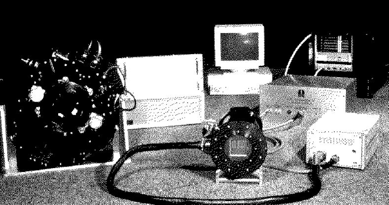
The nitrogen tank (Fig. 1) has a three liter capacity which keeps the focal plane at a temperature of C for more than 24 hours. A pressure of Torr is achieved and outgassing is extremely low, in part due to the absence of active electronics within the dewar.
Optical ray tracing analysis shows that the effect on the image quality of the curvature of the 5 mm thick, 140 mm diameter quartz window due to the vacuum is negligible. However, the image quality of the wide-field corrector does slightly degrade radially, so it is preferable to focus towards the outer parts of the field to insure the optimum image quality over the whole mosaic.

2.2 CCD acquisition hardware architecture
The CFHT GenerationIII controller (Kerr et al. 1994) is based on the San Diego State University CCD controller and VME interface board (Leach 1988). Figure 2 shows the system architecture where only one analog card is represented. A long shielded cable (2 m) connects the dewar to the controller box which houses a utility board and the four analog cards controlled in parallel by the timing board. The temperature regulation and shutter timing are controlled by the utility card. Each analog card contains one video processor and all digital to analog converters (DACs) to produce the various voltages to run a CCD. With such a configuration, each CCD of the mosaic is completely isolated from the other chips, except for the ground plane, hence strongly reducing the risks of interchip crosstalk and noise injection. Although the four CCDs are read out in parallel, the four pixels are sent sequentially to the VME interface board through the fiber optic on the host SUN SPARCengine 1E. The data are stored in a shared memory segment and then descrambled and written to disk.
In the new CFHT release of the GenIII system, there is a dewar identifier that prevents downloading and executing another chip DSP code that could potentially damage the detector.
2.3 The Pegasus CCD software
The new CCD software takes advantage of the features of the last Pegasus release and the use of a new powerful Hewlett Packard workstation 9000-747i using the PA-RISC 7100 processor running at 100Mhz. The Pegasus CCD software has been upgraded to allow fast and efficient acquisition of large images from multi-output cameras. Putting the data from all four chips into a single 33 Mbyte FITS file is still reasonable and greatly simplifies the tasks of file managing, archiving and preprocessing. Also, it gives the observer the ability to check the whole field in a single SAOimage window. The drawback is the extra time taken by the descrambling process that rearranges the data into a single FITS file as they appear on the sky. The latest Pegasus release allows the data to be concurrently written to NFS disk through the network as they are coming into the shared memory of the SPARC1E. Unfortunately it cannot descramble the data, and this process must be implemented on the HP station.

There are four concurrent processes running in parallel: the DSP program running on the timing board in the CCD controller that reads out the mosaic in parallel and sends the data sequentially through the fiber optic, the DSP program running on the VME interface board in the SPARC1E (the CCD computer) taking the data from the fiber optic and putting them in the shared memory, a Unix process running on the SPARC1E, basically writing the data as fast as possible from the shared memory to the NFS disk (local disk for the HP) as the data fill the shared memory, a program on the HP that loads the incoming data into memory data from its local disk and descrambles it. Once the last pixel is read, all the data are already descrambled and the image memory segment is then written to disk in less than 20 s. The main limiting factor is the write-to-disk through the network. The readout of the mosaic to the shared memory takes 170 s (40 s per burst of four pixels), whereas the NFS write to disk is about 220 s long. The descrambler does not add time and hence the complete readout time is 240 s.
This multi-output camera software is modular and can manage standard single output systems or simply read out a single CCD within the mosaic for raster selection and focusing. This software can be extended to larger mosaics like the future ten output CFH10K camera. The Pegasus user interface is identical to the standard FOCAM session and the multi-output feature is invisible at this level. The observers see MOCAM as a monolithic 4K4K CCD where subraster selection is possible as with any single detector, except that subrasters that span more than one CCD are not permitted. The interactive display of the data is simplified as the observers have a full 4K4K image in the SAOimage window at the end of each exposure. A complete acquisition cycle within the Pegasus session, including the display (20 s), takes less than 5 minutes. Even with 33 Mbytes per image, it is still convenient to save the data on DAT tapes or Exabyte tapes which both provide storage capacities of at least 4 Gbytes.
As for all CFHT data, the images are archived at the Canadian Astronomy Data Center (CADC). The CFHT archiving system consists of a deamon on a dedicated machine that saves, through the network, the data on a optical disk. Since all frames, regardless of their content, are archived, a huge amount of data is accumulated during the MOCAM runs and even with a 3 Gbytes per side capacity, the disk has to be changed every four days.
2.4 Filter wheel and shutter
The filter wheel and associated electronics are based on a Pro-Log controller running DAO’s Universal Controller Kernel software, which was designed, built and optimized at DAO. This software originates from the HRCam project (McClure et al. 1989). The filter position is managed from the MOCAM Pegasus session through a serial server as shown on Fig. 3. This server gets the commands from the session host over the network via the MUSIC client server protocol (Multi-User System for Instrument Control developed at the Lick Observatory) handling the Pegasus communications between all networked computers used at CFHT.
Two stepping motors control the filter wheel rotation and positioning with a repeatability of 5 m which is small compared to the pixel size (15 m). This guarantees a constant flat-field pattern which is easily removable by standard techniques. The time required to select a new filter is about eleven seconds and a confirmation message is sent to the user’s session which allows the checking of the instrument hardware status at any time. The five positions of the filter wheel presently hold four interference filters made by Barr Associates: B, V, R and I; the transmission curves are shown in Fig. 5. The filter size is 85 mm85 mm, much larger than the mosaic size (61 mm), and the thickness ranges from 4.6 mm for the V filter to 7.0 mm for the B filter.
The shutter is under the control of the CCD controller to ensure accurate timing. However exposures shorter than ten seconds suffer from the slow mechanical response of the large iris shutter (diameter 150 mm) that opens in 50 ms and closes in 200 ms, the center part of the field being exposed longer than the outside. Hence, very short exposures will yield unreliable photometric data and are not recommended. Short exposures on bright standard stars should be avoided, but defocusing these stars will lead to longer exposure times. The standard dome and twilight flat-fielding techniques that use short exposure times become inaccurate for ultra-deep imaging, and superflats (Tyson 1990) are indispensable. Surma (1993) proposed a method to calibrate the shutter response on short exposure images, but the superflat option remains more efficient, providing better precision on both small scales and large scales with a relatively small number of images.
2.5 Optimization and performances
2.5.1 Hardware optimization
Operating MOCAM in the prime focus cage of the CFHT is more difficult than on the laboratory bench. The electronic environment of the bonnette and the high-power electronics of the telescope and the dome generate additional noise through electronic coupling. The main concern was the long cable (2 m) connecting the CCD output to the controller housing the pre-amplifier (Fig. 4). This cable provides the possibility of mounting the controller separately from the rotating prime focus bonnette, but the controller was eventually mounted on the side of the dewar for security and performance reasons. During the design of the camera, the challenging problem of controlling interference was addressed, and a very highly shielded cable was built. This cable consists of four CCD harnesses completely insulated from each other to prevent interchannel crosstalking through capacitive coupling. Driving the four CCDs completely separately with the use of independent analog cards for each CCD avoids crosstalk between on-chip amplifiers which can occur when the same voltage source is used for several outputs.
The ground plane was tested and adapted on the telescope. The best configuration is a ground spider centered on the backplane of the CCD controller box while the dewar is turned into a Faraday cage by a thin boron nitride layer between the nitrogen tank cold finger and the focal plane. This layer ensures good thermal conduction while keeping the CCDs electrically insulated from the dewar body. All other power sources are kept away from the CCD controller. A high-frequency herringbone pattern appeared on bias frames at the telescope and were found to be generated by interference between the readout and another source. It was corrected by carefully adjusting the pixel frequency to s. Eventually, with this highly-protected environment, the noise in the bias frames was reduced to about 6 electrons, with neither small nor large scale patterns.
The detector security is a priority at this high altitude (4200 m) where the dryness of the air often creates favorable conditions for electrostatic discharge. The use of the dewar as a Faraday cage was also motivated by this threat. Furthermore, voltage overshoots occurring at CCD controller power up and down are particularly dangerous on this first version of the SDSU controller used with MOCAM, as they inject voltages on the CCD well beyond the rated tolerances of the components. Hopefully, the new generation of SDSU controllers is designed to set up the voltages properly and safely.
The frequency of the thermal regulation cycle can generate additional noise on the detector readout. We disabled the thermoelectric regulation, preferring to adjust the number of metal strips of various thickness that conduct the heat from the cold finger to the nitrogen tank (Fig. 1). When used in the downward configuration at the prime focus, the temperature stabilizes at C with variations less than 2 degrees during the whole night, well below the point where the temperature strongly influences the dark current generation and quantum efficiency. The drawback of this method is the longer time required to cool down the mosaic perfectly, almost 12 hours. The boron nitride layer (0.5 mm thickness) has little influence on this time.
2.5.2 CCDs tests and performances
The Loral foundry first produced calibration images at room temperature for each chip when they were still on the wafer. This facilitated a first selection of the best chip according to the apparent number of bad cosmetics and CTE problems. The selected CCDs were cut and mounted by Loral on kovar packages. Prior to integration in the mosaic focal plane, each CCD was individually tested and optimized at DAO at cryogenic temperatures. Tests included gain and CTE measurements with a 55Fe radioactive source, and linearity and cosmetic quality evaluation with an integrating sphere. All these parameters were optimized through the control of the parallel and serial transfer clocking voltages, and the output amplifier bias and clocking voltages.
All the tests had to be repeated at Toulouse once the best CCDs were put together in the MOCAM dewar. In order to find the optimal behavior of the four CCDs when run together, we considerably improved the automation of the sequences, in particular on the optical bench, in the data acquisition processes, and in the data reduction and data analysis. This allowed us to secure a large number of measurements for all sets of parameters automatically and to determine the optimum performance of the camera with a high level of confidence.
Commonly used to determine the gain and the CTE, the 55Fe source has the disadvantage of requiring a change of the quartz window with a beryllium plate or a metal cover with the 55Fe source mounted inside. To avoid changing the window, we also used a radioactive tritium source (a twelve years decay radioactive source interacting with a phosphorescent envelop generating optical photons) with the quartz window to determine the gain, the linearity and the full well pixel capacity through the photon transfer curve (Janesick et al. 1987). A large integrating sphere was used to test detector uniformity, the parallel and serial CTE through the extended edge response method, and to determine a map of cosmetic defects with low level flat-fields. The intercalibration of the four detectors showed that the quantum efficiency is very uniform from one chip to another if they originate from a same wafer lot. Measurements of the gain and CTE with the tritium source appeared to be very close to the results obtained with the 55Fe source and good enough for the precision required to qualify a CCD for an astronomical use. The characteristics of the four CCDs are very similar and summarized in Fig. 5.
As mentioned before, chip-to-chip crosstalk was a serious concern and this topic was largely tested on the optical bench. Various pickup noises were canceled thanks to shielding and appropriate design of the voltage plane. Simulating a very luminous star on one CCD allowed us to set up properly the delays in the video processing sequence (Cuillandre et al. 1995) and to eliminate crosstalk (ghost images) through capacitive coupling to a level of 0.5% between the video cables. Aperture photometry on the ghost images indicates the crosstalk was efficiently eliminated.

2.5.3 Dynamic anti-blooming
During the first observing run on the telescope in November 1994, contamination by blooming from bright stars appeared to be a serious limitation for the detection efficiency. They actually contaminate a large area of the CCD by charges spreading up and down along the columns. Janesick et al. (1992) proposed a new technique to cancel the blooming by luminous stars, dynamic anti-blooming, that has been successfully implemented by several observatories (e.g. Neely et al. 1993). Two parallel clock phases, P1 and P2 for our Loral CCDs, are clocked during integration while the barrier phase P3, the doped channel, remains inverted. This clocking sequence allows surplus electrons to recombine with holes at the Si-SiO2 interface when the two collecting phases P1 and P2 invert. The efficiency of this technique, say the number of surplus charges that can be eliminated, depends on the frequency of the clocking.

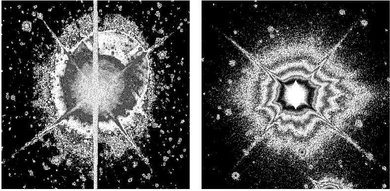
Contamination by bright stars has two consequences, a halo and blooming. The halo can be large and obliterates objects of scientific interest within this area, while the blooming contaminates the data much further away but only on a limited number of columns (Fig. 9, left). The optimum clocking frequency for MOCAM is chosen to reduce the blooming within the halo of stars fainter than 8th magnitude on exposures less than 30 mn long (the probability of finding an 8th magnitude star in a one degree field is close to one). An artificial star on an optical bench was used to measure the effectiveness of dynamic anti-blooming as a function of frequency. Figure 6 shows the size of the blooming tail versus exposure time for different frequencies. The tail size increases non-linearly as each pixel acts as an individual pump, and the upper limit depends on the star brightness and the frequency. The anti-blooming pumping efficiency increases linearly over a wide range of anti-blooming frequencies (12 Hz to 400 Hz) with a slope of 500 s-1pixel-1Hz-1, a typical value for Loral CCDs (Kohley et al. 1995). We found the 25 Hz frequency to be optimal for our imaging application at the CFHT prime focus. As proposed by Janesick for the Loral CCDs (Janesick et al. 1992), the optimal levels for the collecting phases are V and V. This second level is higher (V) than the normal voltage used during charge transfer to improve the charge collection. The usual drawback of this technique is an increase of the dark current and the generation of spurious noise due to the rising and falling slopes of the two phases during the clocking. This noise is uniform on the whole detector and increases linearly with the clocking frequency with a slope of s-1pixel-1Hz-1. This noise is remarkably low for the MOCAM CCDs, but was about ten times higher for similar chips coming from a previous run. The silicon quality seems a critical issue. CCDs from the earlier run suffered from an abnormally high dark current when operated at C. Remarkably, dynamic anti-blooming decreased this dark current by a factor of two over the standard MPP mode (see also Janesick et al. 1992).

The behavior of MPP mode noise versus signal and anti-blooming mode (ABL) noise versus signal plotted on figure 7 is different. The rough equation for CCD noise (in ADU) at high flux is (Janesick et al. 1987):
where is the average flux in the area in ADU, is the inverse gain in ADU-1 and is the quantum efficiency non-uniformity from pixel to pixel. This latter term is a result of physical differences between the photosites of each pixel, and its effect can be seen in figure 7 in the high signal regime as the data departs from the line indicating pure photon statistics. The value for can be directly measured from the average of a large number of uniformly-illuminated images, i.e., a flat-field. We found a typical value of 0.9% for the MPP mode and 0.4% for the ABL mode. This difference can be understood by examining the behavior of the photosites in the two cases. In MPP mode, the charge collection area is a result of the barrier implanted under phase 3, and any lithographic or small scale process variations during CCD fabrication in the definition of that barrier will become manifest as . During normal (non-MPP) modes, the charge collection area of a pixel is centered on and dominated by the positive phase(s). In ABL operation, which also has at least one phase positive as in the normal mode, the center of the charge collection area moves between two phases, which tends to average out some of the process variations and reduce the value of . It should be possible to further reduce this pixel response non-uniformity by clocking three phases during an exposure, at the expense of reduced resolution, as the average photosite during an exposure is broadened. In any case, the reduction of systematic errors always leads to an improvement of the data quality.
2.5.4 Tests and validation on the sky
The first tests on the sky occurred in November 1994 during a fourteen night run for Canadian and French weak lensing programs. Engineering nights were also allocated to fully evaluate the instrument on the sky. Observations in the V, R and I filters of a large stellar field, like SA 98 (Landolt 1992), showed that the image quality is uniform on the whole mosaic. Observations of this field while keeping the telescope motionless produced a large number of straight lines on the mosaic which yielded a precise measurement of the misalignment of the four chips. The deviation is about two pixels over the whole length of a chip (0.03 degree). The astrometry of the mosaic with respect to the positions of the four quadrants in the single output FITS file was easily obtained through two offset observations of the stellar field.
The intercalibration of the chips and the relative efficiency in different filters were also made using the field of SA 98 (Fig. 5). A series of calibration images was also taken during the day using dome-flats to build a photon transfer curve of the CCDs when mounted on the telescope. This test was necessary to check that the response of the detectors was still the same, despite substantial changes of the environment, air temperature, humidity and noisy electronic neighbors. A second run benefited from implementation of the dynamic anti-blooming technique which proved to be very efficient on stars as bright as 8th magnitude as shown on Fig. 9 (right) where the blooming is contained within the halo area. The observation and the photometric analysis of this stellar field (SA 110) both in MPP mode and anti-blooming mode (only at the 25 Hz frequency) confirmed that the photometry and the PSF are not affected.
Thanks to the large amount of data obtained on blank fields, superflats in different colors could be obtained. Due to their specific file format and the systematic loading of the whole image in memory, standard software packages like IRAF or MIDAS are inadequate for processing large images. With the large size of each image and the large number of images required to build a proper superflat, we developed dedicated pre-processing FITS tools in C to allow fast and easy pre-reduction of the data. These programs work with buffered access to the file and do not require a lot of memory.
3 Constraints of wide-field observations at CFHT prime focus
A few months after the arrival and the first observations of MOCAM at CFHT, the UH8K mosaic, a mosaic of eight 2K4K frontside-illuminated Loral CCDs (Metzger et al. 1996), was used at the prime focus of CFHT for solar system studies, weak lensing observations and for the detection of dust in the outer regions of M 31 (Cuillandre et al. 1996). With a field of view, this camera covers 25% of the prime focus field, offering a significant advantage for these types of wide-field programs as compared to the field offered by MOCAM. Through the experience gained during the observations and the reduction of the MOCAM and UH8K data, we found several constraints and limitations due to the combination of the use of the prime focus, its wide-field corrector and large CCD mosaics in general.
3.1 Distortion and image quality
The wide-field corrector has a well known radial distortion function established from the analysis of photographic plates and reproduced from raytrace analysis of the prime focus optics. Based on the notation used by Chiu (1976), the true radial distance (mm) can be computed from the radial distance (mm) measured on the detector:
is greater than and the corresponding true field angle on the sky in arcminutes is where the multiplicative coefficient is the scale at the center of the field in arcmin mm-1. This type of distortion is common for wide-field correctors. The presence of this distortion eliminates the possibility of drift scanning with very large mosaics with the present CFHT wide-field corrector.
The geometry of the field is an important issue for scientific programs demanding accurate positions of objects. Fortunately, this distortion acts only at large scales and the local PSF is not affected. This point was demonstrated from the high image quality data obtained with MOCAM and the UH8K. However the image quality is more sensitive in the outer parts of the field, so focusing should be carried out near the edges of the mosaic. Whatever the procedure used, focusing still remains among the most crucial and delicate processes at CFHT.
Strong distortion can also have an impact on the shift-and-add procedure. If the offset is too large, the distortion will cause objects not to line up perfectly when attempting to build a composite image with just vertical and horizontal displacements. One could avoid this problem by keeping the shifts small (less than or of order 10′′), but this will result in poor superflats and in not filling the gaps between mosaic elements. In practice, resampling the images is inevitable, to correct both for the slight offsets and orientations of the individual mosaic elements, and for the geometric distortion. This task requires powerful computing facilities, and accurate astrometric calibration of the mosaic.
3.2 Reflection and diffusion
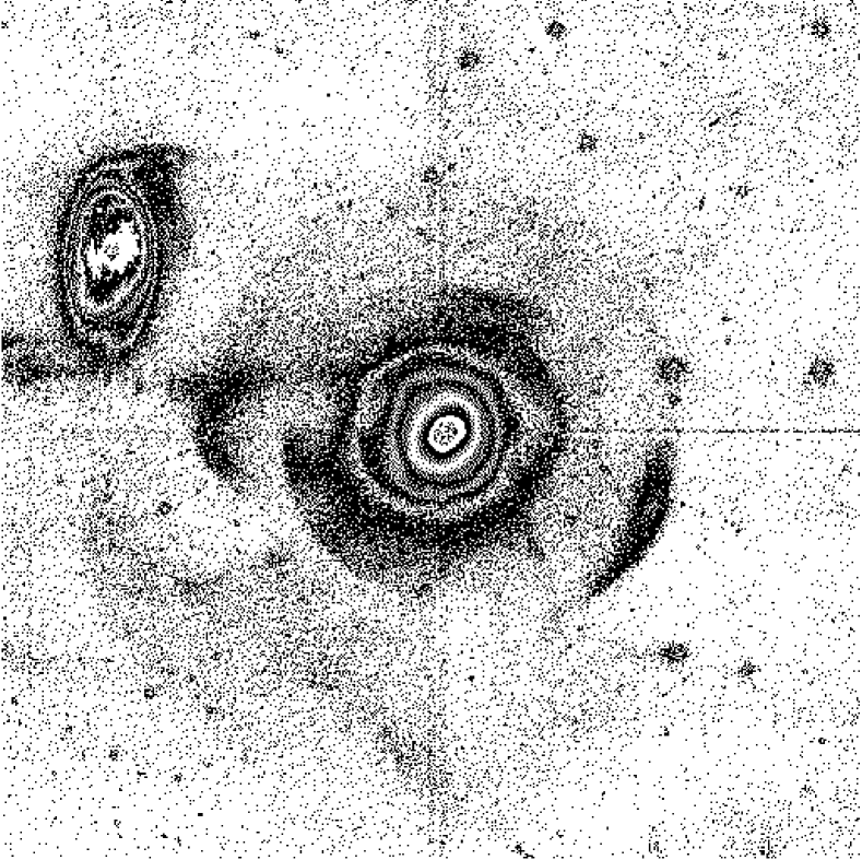
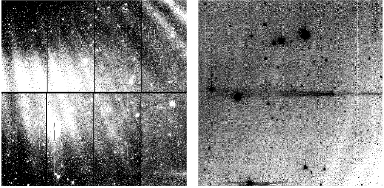
Another limitation of wide-field imaging on large telescopes comes from off-axis reflections and scattered light from bright stars. Over the whole sky, the probability of finding an 8th magnitude star in a one degree field is close to one. Brighter stars are often found in the neighborhood of the target field, as we experienced during the MOCAM and UH8K observations. If the star is in the camera field of view, the main consequence will be a large halo due to multiple reflections between the filter, the dewar window, the CCD itself, and the optical elements of the wide-field corrector (Fig. 9, left). When the star is outside the field, reflections on some mechanical parts of the wide-field corrector and/or off-axis prime focus guider create beams that seem to enter the dewar horizontally as shown in Fig. 10. These observations demonstrate that the high dynamic range and sensitivity of CCD detectors uncover factors that could limit the performance of future observations. Diffuse light is presently a strong limitation factor in deriving reliable flat-field calibration images that allow flattening the data to better than from the sky background. Proper baffling of some part of the optical path as proposed by Grundahl et al. (1996) may improve the correction to about which would be a major improvement of the detection limit and would open new possibilities for the study of extended, faint surface brightness, objects.
4 Conclusion
The CFHT now has a full wide-field imaging facility working in the Pegasus environment that can be used by any observer. Its performance for astronomy is basically the same as the usual FOCAM instrument equipped with thick CCDs, but with further attractive upgrades: a field of view which is four times larger and dynamic anti-blooming, multi-output, fast readout features. The first observations at prime focus have shown that the image quality is excellent over the whole field and in all the wavelength range (from V to I). Images as good as FWHM=042 have been achieved by Fahlman et al. (1995, private communication). The MOCAM FITS files are 33 Mbytes each, but do not require special computing facilities, nor dedicated software. Although we emphasised that buffered access to the files provide more tractable access to data, standard software like IRAF or MIDAS can also be used if the mosaic is cut into four images. First scientific results on faint halos around edge-on spiral galaxies (Lequeux et al. 1996b) demonstrate that MOCAM is a competitive instrument. Its future use on the CFHT adaptive optic bonnette (Arsenault et al. 1995) at the cassegrain focus will provide a field of 90′′ at a scale of 002 pixel-1.
Our experience gained in wide-field imaging at CFHT with MOCAM and UH8K help to improve the imaging facility at CFHT, and to prepare the arrival of the next generation of large CCD mosaics. In the near future, the Pegasus system will incorporate a real time core that will allow faster data acquisition. The network will no longer be used and the data will go directly from the CCD controller to the HP memory. In the longer term, improvements of the wide-field corrector and the telescope baffling are indispensable to reduce scattered and diffuse light in the telescope. This will considerably lower the background light and the flat-field residuals. The guide probe appeared to be a real problem in fields where a guide star couldn’t be found outside the camera field. The resulting vignetting on the mosaic obliterates the data. Further developments for star selection based on deeper guide star catalogs will be required, or even the design of a new bonnette, particularly with the arrival of the one degree field 16K16K camera. If these improvements are made, it will be possible to make ultra-deep wide-fields surveys at the CFHT prime focus.
The authors wish to thank Bernard Fort for his essential initial impulse to the project, the Loral Fairchild Imaging Sensor company for their support to our project, and all the CFHT staff, particularly Steve Massey for his help during the setups on the telescope and Tim Abbott for his contribution to the commissioning of MOCAM. We wish to thank all the members of the instrument groups who have contributed to this project: P. Couderc, G. Delaigue and H. Valentin at OMP, B. Leckie and A. Moore at DAO and R. Arsenault, B. Grundseth, D. McKenna, S. Milner and J. Thomas at CFHT.
References
- Arnaud et al. 1994 Arnaud, M., Aubourg, E., Bareyre, P., Brehin, S., Caridroit, R., De Kat, J., Dispau, G., Djidi, K., Gros, M., Lachièze-Rey, M., 1994, ExA, 4, 279
- Arsenault et al. 1995 Arsenault, R., Salmon, D., Kerr, J., Rigaut, F., Crampton, D., Grundman, W., 1995, Proceedings on the Workshop on Astronomy with the CFHT Adaptive Optics Bonnette, 1
- Bonnet et al. 1994 Bonnet, H., Mellier, Y., Fort, B., 1994, ApJ, 427, L83
- Bonnet et al. 1995 Bonnet, H., Mellier, Y., 1995, A&A, 303, 331
- Bredthauer 1995 Bredthauer, R.A., 1995, Grand Cayman Conference proceeding, in press
- Crampton 1992 Crampton, D., 1992, Proceeding of the Third CFHT User’s Meeting, 52
- Chiu 1976 Chiu, L.-T.G., 1976, PASP, 88, 803
- Christian 1989 Christian, C., Brewster, J., McGonegal, R., Grundseth, B., Kerr, J., Smith, S., Waddell, P., 1989, , A.S.P. Conference Series, 8, 209
- Cuillandre et al. 1995 Cuillandre, J.-C., Mellier, Y., Murowinski, R., Crampton, D., Luppino, G. and Arsenault, R., 1995, IAU Symposium No. 167, Kluver Academic Pub., 213
- Cuillandre et al. 1996 Cuillandre, J.-C., Lequeux, J., Mellier, Y., Allen, R. J., 1996, A&A, submitted
- Fahlman et al. 1994 Fahlman, G., Kaiser, N., Squires, G., Woods, 1994, ApJ, 437, 460
- Geary et al. 1990 Geary, J.C., Robinson, L.B., Sims, G.R., Bredthauer, R.A., 1990, SPIE, 1242, 38
- Grundahl et al. 1996 Grundahl, F., Sorensen, A.N., 1996, A&A Supplement, 116, 367
- Janesick et al. 1987 Janesick, J., Elliot, T., Collins, S., Blouke, M., Freeman, J., 1987, Optical Engineering, 26, 692
- Janesick et al. 1992 Janesick, J., Elliot, 1992, ASP Conference Series, 23, 1
- Kerr et al. 1994 Kerr, J., Clark, C.C., Smith, S.S., 1994, SPIE, 2198, 980
- Kohley et al. 1995 Kohley, R., Reif, K., Pohlmann, T., Müller, P., 1995, SPIE, 2415, 67
- Landolt 1992 Landolt, A.U., 1992, AJ, 104, 340
- Leach 1988 Leach, R.W., 1988, PASP, 100, 1287
- Lequeux et al. 1996a Lequeux, J., Guélin, M., 1996a, Proceeding of the New Extragalactic Perspectives in the New South Africa, Kluver Academic Pub.
- Lequeux et al. 1996b Lequeux, J., Fort, B., Dantel Fort, M., Cuillandre, J.-C., Mellier, Y., 1996b, A&A, in press
- Luppino & Miller 1992 Luppino, G.A., Miller, K.R., 1992, PASP, 104, 215
- Luppino et al. 1994 Luppino, G.A., Bredthauer, R.A., Geary, J.C., 1994, SPIE, 2198, 810
- Luppino et al. 1995 Luppino, G.A., Metzger, M., Miyazaki, S., 1995, IAU Symposium No. 167, Kluver Academic Pub., 297
- McClure et al. 1989 McClure, R.D., Grundmann, W.A., Rambold, W.N., Fletcher, J.M., Richardson, E.H., Stilburn, J.R., Racine, R., Christian, C.A., Waddell, P, 1989, PASP, 101, 1150
- Metzger et al. 1996 Metzger, M., Luppino, G., Miyazaki, S., 1996, PASP, submitted
- Neely et al. 1993 Neely, A.W., Janesick, J.R., 1993, PASP, 105, 1330
- Surma 1993 Surma, P., 1993, A&A, 278, 654
- Stubbs et al. 1993 Stubbs, C., Marshall, S., Cook, K., Hills, R., Noonan, J., Akerlof, C., Alcock,C., Axelrod, T., Bennet, D., dagley, K., Freeman, K., Griest, K., Park, H.-S., Perlmutter, S., Peterson, B., Quinn, P., Rodgers, A., Sosin, C., Sutherland, W., 1993, SPIE, 1900, 192
- Tyson 1990 Tyson A.J., 1990, J. Opt. Soc. Am. A., 7, 1231
- Vigroux 1995 Vigroux, L., 1995, Proceeding of the Fourth CFHT User’s Meeting, communication