A relativistic partially electromagnetic planar plasma shock
Abstract
We model relativistically colliding plasma by PIC simulations in one and two spatial dimensions, taking an ion-to-electron mass ratio of 400. Energy dissipation by a wave precursor of mixed polarity and different densities of the colliding plasma slabs results in a relativistic forward shock forming on millisecond timescales. The forward shock accelerates electrons to ultrarelativistic energies and reflects upstream ions, which drag the electrons along to preserve the plasma quasi-neutrality. No reverse shock forms. The shock may be representative for internal gamma ray burst shocks.
pacs:
98.70.Rz,52.35.Tc,52.65.Rr,52.27.NyAccreting compact objects like neutron stars or black holes are amongst the most energetic environments in the universe. Such systems can range from microquasars through active galactic nuclei to gamma ray bursts (GRBs) Piran ; Piran2 ; Waxman ; Zensus . Common to these objects is the ejection of a relativistic jet that is probably accelerated by magnetic fields Bland ; Nishikawa3 . GRB jets are ejected by a forming compact object Nature . Their high Lorentz factor introduces a radiation beaming, making GRBs detectable at cosmological distances. The GRB emissions are explained either by the fireball model, in which the plasma kinetic energy dominates Piran ; Piran2 , or by the electromagnetic model, in which the Poynting flux is dominant EM ; Lyutikov . We consider the fireball model.
The high energies involved in the thermalisation of relativistic jets imply that plasma structures form, such as phase space holes Hole . A shock description needs a kinetic approach Fahr . Particle-in-cell (PIC) simulations have modelled the external GRB shock between the jet and the ambient plasma Nishikawa1 ; Silva1 ; Silva2 ; Hededal ; Frederiksen ; Nishi3 , and have examined the magnetic field amplification and particle acceleration. The weakly magnetized external GRB shocks develop out of a broad wave spectrum Medvedev ; Bret1 ; Bret2 ; Tautz , and are thus filamentary. The internal shocks, powering the prompt emissions, form closer to the collapsing star with its strong magnetic fields. The magnetic field pressure may initially exceed the thermal pressure of the jet plasma, in contrast to the case considered by Ref. Medvedev . The magnetic field and the high plasma temperature Ryde suppress the filamentation modes Bret3 ; Nishikawa2 ; Dieck2 and other wave modes can develop.
The finite grid instability requires a high spatial resolution on electron timescales of multi-dimensional PIC simulations Dieck1 , while a relativistic shock will extend over ion scales. A large ion-to-electron mass ratio is required to model shocks Scholer . To account for these constraints, we select the initial conditions such as to physically confine the plasma dynamics to one spatial dimension (1D) and three momentum components, which allows us to restrain also the simulation geometry to one spatial dimension. We verify the validity of this assumption with the help of a two-dimensional (2D) simulation. We demonstrate that the magnetic field results in the formation of a relativistic planar shock. The energy dissipation is provided by a wave with mixed electrostatic and electromagnetic polarity, probably a nonlinear oblique whistler Oblique . This contrasts the energy dissipation by the purely electromagnetic filamentation modes considered in Refs. Silva1 ; Silva2 ; Hededal ; Frederiksen ; Nishikawa2 ; Nishi3 , and the nonrelativistic electrostatic shocks modelled in Refs. Scholer ; Sorasio . Different slab densities Sorasio facilitate the development of a shock with a Mach number of 40 and an Alfvénic Mach number of 10. The forward shock reflects upstream ions.
PIC simulation methods Eastwood solve the Maxwell equations and the relativistic equation of motion
| (1) | |||
| (2) | |||
| (3) |
and fulfill and as constraints. The electric and magnetic fields are defined on a discrete grid. Each computational particle (CP) with index of the species has the charge and mass with , where and are the physical charge and mass of the particles, represented by the species . The particle momentum is .
Two plasma slabs collide in the simulations at the position , each consisting of the electrons and ions. The ion-to-electron mass ratio is . The plasma frequency of the species with the number density is . The electrons of slab 1 have and the ions . The dense slab 1 is initially moving with the positive speed along the direction. The electrons and ions of slab 2 have and , respectively. The tenuous slab 2 moves with the speed along the direction. Initially, all mean speeds along the directions vanish. All plasma species have the observed jet temperature keV Ryde . The position and time have the units of the electron skin depth and , where is the speed of light in vacuum. Each slab initially occupies half of the simulation box. The slabs collide along the direction at the speed , which is representative of internal GRB shocks Piran2 . We introduce a spatially homogeneous oblique magnetic field. The magnetic field component with suppresses the filamentation instability Bret3 and a perpendicular enhances the energy dissipation. Initially, we set . The initial magnetic field strength is thus . The initial box-averaged plasma kinetic energy density exceeds the magnetic field energy density by a factor of . The 1D simulation box length is , which is resolved by cells. The 2D box has the extent ( cells) and ( cells) along the and directions, respectively. The boundary conditions are periodic. The 1D (2D) simulation time is (). The 2D simulation represents each plasma species by 64 particles per cell (PPC). The 1D simulation resolves each species of the dense (tenuous) slab by 576 (256) PPC.
The electric field in the 2D simulation plane at in Fig. 1 reveals a planar structure at , the leading edge of the dense plasma slab. A similar distribution is not shown. The filamentation instability would lead to the structure formation on a scale of along , and it is here suppressed by Bret3 . No strong field is present at .
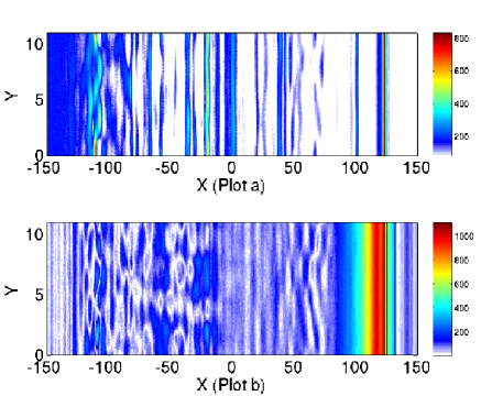
We exploit the planarity of the slab front in Fig. 1 and resort to the 1D simulation with its better statistical plasma representation.
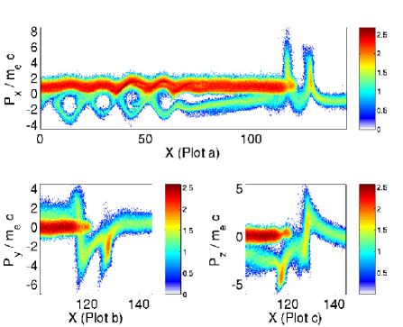
The electrons of the tenuous slab are deflected by the oblique magnetic field that is frozen into the dense downstream plasma. Since the massive upstream ions are not significantly deflected, a current and thus the electric field is building up at the leading edge of the plasma slab in Fig. 1. Further downstream, Fig. 2(a) shows the electron phase space holes, which thermalize the electrons, as in Ref. Dieck2 . These are also observed at the Earth bow shock Bale .
The energy dissipation by the electric fields eventually modulates the electrons of the dense plasma slab, giving rise to larger electric fields. Consequently, Fig. 3 demonstrates that the
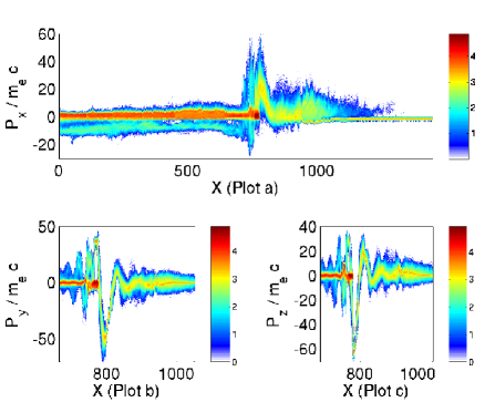
electrons are accelerated to factors of tens to hundreds and follow a corkscrew orbit. The relativistic mass of the electrons is not small compared to at . Figure 4(a) shows the ion response to the strong fields.
The spatial interval with the strongest particle acceleration at is well behind the expected slab front at . Some ions have been accelerated beyond the initial velocity by the electric field at the slab front Dieck2 and they have propagated farther upstream beyond .
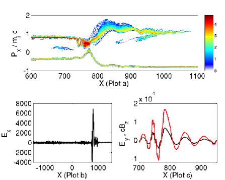
The wave modes at that grow only close to the leading edge of the dense plasma slab, as Fig. 4(b) exemplifies for the field component, could have originated from an oblique whistler instability, similar to that discussed in Ref. Oblique . The wave growth at is suppressed or delayed. This will introduce an asymmetric plasma dynamics in the intervals separated by .
The wave amplitudes in the considered plasma scale linearly with if all ratios between remain the same as discussed, for example, in Ref. Wakefield . The wave is circularly polarized, which explains the electron corkscrew orbits in Fig. 3. The peak value of in Fig. 4(c) exceeds the initial background magnetic field with V/m, and the wave in Fig. 4(c) is nonlinear. The mixed polarity of the waves allows them to interact with the plasma through their electrostatic component. The wave amplitude is sustained, because the wave is driven by the dense plasma slab that compensates damping losses. The damping may explain why and are in phase in Fig. 4(c).
At , the ion distribution in Fig. 5(a) has developed into a shock.
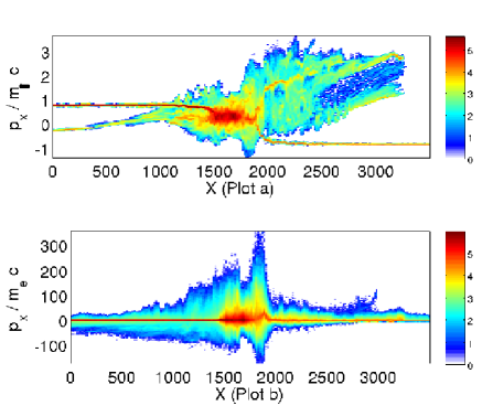
The foreshock in the interval is formed by incoming and shock-reflected ions. The electron transport with the shock-reflected ions across the upstream in Fig. 5(b) ensures the plasma quasi-neutrality. The two ion beams at result from the delayed shock formation. At , the values of the electrons are comparable to those of the ions multiplied by in the simulation reference frame. A Lorentz transformation of the electron velocity into the upstream frame, which moves with relative to the simulation box frame, yields a peak electron for our . In comparison, the filamentation instability in Ref. Nishi3 yields only a peak electron for a collision speed with . The planar electromagnetic shock considered here is a stronger electron accelerator.
The shock in Fig. 5 has formed during the time , which is 7 ms in physical units. If we assume that this shock would constitute an internal shock of a GRB and that the jet frame moves at a , the time dilation would yield a duration of seconds for the shock development in the Earth (observer) frame of reference. This is comparable to the timescale of the prompt emissions. The shock we consider is likely to form during a longer time for . The bulk Lorentz factor of GRB jets may, however, also be less than Waxman . Different jet plasma densities, which may be higher than we consider in this work Meszaros , do not strongly affect the shock development time due to a scaling of the timescales with the square root of the density Wakefield .
In summary, we have examined the collision of two plasma slabs with different densities at a relativistic speed. The bandwidth required to model the plasma dynamics at a high ion-to-electron mass ratio cannot be realized at present with PIC simulations in more than one spatial dimension due to the necessary large box size Waxman and the high-resolution grids that are required in higher dimensions to suppress the electromagnetic finite grid instability Dieck1 . The quasi-parallel magnetic field has, however, suppressed the beam filamentation, and the initial planar shock development may thus be well-approximated by a one-dimensional PIC simulation. The energy dissipation has been accomplished through a nonlinear wave of mixed polarity, which could have originated from an oblique whistler instability. Whistlers are frequently observed also at slower quasi-parallel plasma shocks and they are known to be efficient particle accelerators Vol . The large energy dissipation, which ultimately forces the shock to form, is likely to distort the guide magnetic field and the slab boundary would likely be deformed by the ram pressure excerted by the upstream plasma. However, a significant distortion of the guide magnetic field away from the flow-aligned direction introduces a stronger perpendicular magnetic field component. The latter will probably not suppress or delay the shock formation and the plasma thermalization. Our simulation may thus give a correct estimate for the shock formation time even in 3D.
The shock we consider here may thus be representative for a GRB internal shock. Such a rapid shock formation has previously been questioned, at least for purely electromagnetic or electrostatic shocks Brainerd . A Lorentz boost of the electron energy by a transformation from the jet frame into the Earth frame results in electron energies in the GeV-TeV range and could be further enhanced by the thermalization of the shock-reflected ion beam Wakefield ; McClements2 . The shock-accelerated electrons undergo rapid velocity changes at the shock, and may radiate through synchrotron emission Synchrotron and bremsstrahlung Schlickeiser . The suppressed or delayed development of a reverse shock in our simulation may explain the absence of reverse shock signatures in GRB prompt emissions Lyutikov .
Acknowledgments: The DFG (grant SH-21/1-1) and the DIAS (Ireland) have funded this work. The Irish ICHEC and the Swedish HPC2N computer centres have provided computational facilities and support.
References
- (1) T. Piran, Rev. Mod. Phys. 76, 1143 (2004).
- (2) T. Piran, Phys. Rep. 314, 575 (1999).
- (3) E. Waxman, Plasma Phys. Controll. Fusion 48, B137 (2006).
- (4) J. A. Zensus, Ann. Rev. Astron. Astrophys. 35, 607 (1997); R. Fender and T. Belloni, Ann. Rev. Astron. Astrophys. 42, 317 (2004).
- (5) R. D. Blandford and D. G. Payne, Mon. Not. R. Astron. Soc. 199, 883 (1982); R. D. Blandford and R. L. Znajek, ibid. 179, 433 (1977).
- (6) K. I. Nishikawa et al., Astrophys. J. 625, 60 (2005).
- (7) S. Campana et al., Nature 442, 1008 (2006).
- (8) C. Thompson, Mon. Not. R. Astron. Soc. 270, 480 (1994); M. Lyutikov and R. Blandford, astro-ph/0312347 (2003).
- (9) M. Lyutikov, New J. Phys. 8, 119 (2006).
- (10) K. V. Roberts and H. L. Berk, Phys. Rev. Lett. 19, 297 (1967); H. Schamel, Phys. Plasmas 7, 4831 (2000); B. Eliasson and P. K. Shukla, Phys. Rep. 422, 225 (2006).
- (11) H.-J. Fahr and M. Siewert, Astron. Astrophys. 458, 13 (2006).
- (12) K. I. Nishikawa et al., Astrophys. J. 595, 555 (2003).
- (13) L. O. Silva et al., Astrophys. J. 596, L121 (2003).
- (14) R. A. Fonseca et al., Phys. Plasmas 10, 1979 (2003).
- (15) C. B. Hededal et al., Astrophys. J. 617, L107 (2004).
- (16) J. T. Frederiksen et al., Astrophys. J. 608, L13 (2004).
- (17) K. I. Nishikawa et al., Astrophys. J. 642, 1267 (2006).
- (18) M. V. Medvedev and A. Loeb, Astrophys. J. 526, 697 (1999).
- (19) A. Bret, M.-C. Firpo and C. Deutsch, Phys. Rev. Lett. 94, 115002 (2005).
- (20) A. Bret, Europhys. Lett. 74, 1027 (2006).
- (21) R. C. Tautz, I. Lerche and R. Schlickeiser, Phys. Plasmas 13, 052112 (2006); U. Schaefer-Rolffs, I. Lerche and R. Schlickeiser, ibid 13, 012107 (2006).
- (22) F. Ryde, Astrophys. J. 614, 827 (2004).
- (23) A. Bret, M. E. Dieckmann and C. Deutsch, Phys. Plasmas 13, 082109 (2006).
- (24) C. B. Hededal and K. I. Nishikawa, Astrophys. J. 623, L89 (2005).
- (25) M. E. Dieckmann, P. K. Shukla and B. Eliasson, New J. Phys. 8, 255 (2006).
- (26) M. E. Dieckmann et al., Phys. Plasmas 13, 112110 (2006).
- (27) M. Scholer and S. Matsukiyo, Ann. Geophys. 22, 2345 (2004).
- (28) J. Zhao, J. I. Sakai and K. I. Nishikawa, Solar Phys. 168, 345 (1996); R. Ciurea-Borcia et al., Phys. Plasmas 7, 359 (2000).
- (29) G. Sorasio et al., Phys. Rev. Lett. 96, 045005 (2006).
- (30) J. W. Eastwood, Comput. Phys. Commun. 64, 252 (1991).
- (31) S. D. Bale et al., Astrophys. J. 575, L25 (2002).
- (32) M. E. Dieckmann, P. K. Shukla and B. Eliasson, Phys. Plasmas 13, 062905 (2006).
- (33) A. Panaitescu and P. Meszaros, Astrophys. J. 492, 683 (1998).
- (34) Y. Kuramitsu and V. Krasnoselskikh, Phys. Rev. Lett. 94, 031102 (2005); A. Levinson, Astrophys. J. 401, 73 (1992).
- (35) J. J. Brainerd, Astrophys. J. 538, 628 (2000).
- (36) K. G. McClements et al., Mon. Not. R. Astron. Soc. 291, 241 (1997).
- (37) S. M. Tang and S. N. Zhang, Astron. Astrophys. 456, 141 (2006).
- (38) R. Schlickeiser, Astron. Astrophys. 410, 397 (2003).