The empirical Earth rotation model from VLBI observations
Abstract
Aims. An alternative to the traditional method for modeling kinematics of the Earth’s rotation is proposed. The purpose of developing the new approach is to provide a self-consistent and simple description of the Earth’s rotation in a way that can be estimated directly from observations without using intermediate quantities.
Methods. Instead of estimating the time series of pole coordinates, the UT1–TAI angles, their rates, and the daily offsets of nutation, it is proposed to estimate coefficients of the expansion of a small perturbational rotation vector into basis functions. The resulting transformation from the terrestrial coordinate system to the celestial coordinate system is formulated as a product of an a priori matrix of a finite rotation and an empirical vector of a residual perturbational rotation. In the framework of this approach, the specific choice of the a priori matrix is irrelevant, provided the angles of the residual rotation are small enough to neglect their squares. The coefficients of the expansion into the B-spline and Fourier bases, together with estimates of other nuisance parameters, are evaluated directly from observations of time delay or time range in a single least square solution.
Results. This approach was successfully implemented in a computer program for processing VLBI observations. The dataset from 1984 through 2006 was analyzed. The new procedure adequately represents the Earth’s rotation, including slowly varying changes in UT1–TAI and polar motion, the forced nutations, the free core nutation, and the high frequency variations of polar motion and UT1.
Key Words.:
astrometry – reference systems – Earth rotation – VLBI1 Introduction
As we learn from an elementary physics course in high school, the rotation of a rigid body can be represented by three angles. Euler angles are usually selected as parameters, although it is not the only choice. We can say that rotation of an arbitrary body is defined if a functional dependence of Euler angles on time is known.
However, when we are dealing with the Earth, the traditional way of representing the kinematics of the Earth’s rotation is not as simple. In modern textbooks that follow the formalism of Newcomb-Andoyer, for instance, Seidelmann (1992), the Earth’s rotation is represented as a product of 9 matrices that depend on many parameters. Analytical expressions are provided for some of them, but other parameters are supposed to be determined from observations. These parameters are defined though intermediate quantities. These intermediate quantities like the Earth’s rotation axis, the celestial ephemeris pole, the true equinox of date, the non-rotating origin and others, are not objects that can be observed, but idealistic concepts that do not have a clear, intuitive interpretation.
According to the traditional approach, (e.g. McCarthy & Petit, eds. 2004), in order to get the Earth’s orientation at any given moment, one should first compute the values of intermediate parameters that have more than a thousand terms, then interpolate tables of corrections produced by smoothing results of analysis of observations, and finally compute the product of rotational matrices that depend on these intermediate quantities.
At first glance it seems that the complexity of representing the Earth’s rotation is unavoidable, since it should reflect the complexity of a theory for modeling the Earth’s rotation at a level of the accuracy of observations, i.e. on the order of rad111SI units are used throughout the paper. Conversion factors to non-standard units: . This would be true if theoretical models were precise to that level. Roughly speaking, the Earth’s rotation can be considered as consisting of two components, the tidally driven component with precisely known frequencies and the component driven by an exchange of the angular momentum between the solid Earth and geophysical fluids. The latter component is not predictable in principle. The atmosphere contributes to the UT1 at a level of rad, more than three orders of magnitude higher than the accuracy of observations. For a long period of time it was considered that the quasi-diurnal motion of the pole, namely the precession and nutation, can be modeled with a precision comparable to the accuracy of observations. First results of VLBI analysis presented by Herring et al. (1986) shattered this belief. It was discovered that even the most advanced nutation theory of Wahr (1980) was not accurate enough. Numerous attempts to build a theory of tidally driven quasi-diurnal motion were made, but they were not completely successful. In order to reduce the disagreement between theories and observations, the authors had to resort to adjusting some parameters of their theories to quantities derived from the same observations of the quasi-diurnal motion (Mathews et al. 1991, 2002; Getino & Ferrandiz 2001). It was also soon realized that there are two other constituents of the quasi-diurnal polar motion at a level of 1 nanoradian: the free core nutation (Moritz 1987) and the nutation excited by the atmosphere (Bizouard et al. 1998). These constituents currently cannot be predicted and, presumably, they cannot be predicted in principle. Therefore, even if a precise theory of forced nutation is built in the future, one should apply parameters determined from observations in order to represent the quasi-diurnal motion.
Recognizing that both components in the Earth rotation cannot be predicted with accuracy comparable to the precision of observations, prompts us to reconsider approaches to representing the Earth’s rotation and the role of the theory. The quasi-diurnal motion should be described with the use of parameters determined by continuous observations in a similar way as the UT1 and Chandler polar motion. The theory of nutation should be considered not as a tool for data reduction or for predicting the Earth’s orientation, but as means for validating geophysical models. At the same time a theory of the Earth’s rotation can provide valuable guidance for building empirical mathematical models.
The goals of this paper is to build such an empirical mathematical model, to demonstrate using a long dataset of observations that it is feasible and to show that this approach describes the Earth rotation at least as well as the traditional way. It should be noted that an empirical mathematical model has a different meaning than a theoretical model. The theoretical model relates a function of time that describes the Earth rotation with specific properties of the Earth’s body in the form of a solution for the equation of dynamics. The empirical mathematical model relates this function of time to observations using a parameter estimation technique. A minimal requirement for an empirical model is to represent the phenomena with the least possible errors for the entire interval of observations and to provide estimates of uncertainties. We will also try to satisfy two additional requirements: the model should be simple and the parameters of the model should not be strongly correlated. If parameter estimates are strongly correlated, their comparison with theoretical predictions becomes problematic. We will represent the Earth orientation parameters (EOP) in the form of an expansion over a family of basis functions.
The procedure for developing an empirical model of the Earth’s rotation is presented in the rest of the paper. The choice of the a priori model and basis functions is described in section 2, the proposed mathematical models is described in Sect. 3, the strategy of analysis of the 22 year long dataset of VLBI observations is presented in Sect. 4, and the results of solutions are discussed in Sect. 5. Concluding remarks are given in Sect. 6.
2 Choice of the a priori model and the basis functions
2.1 Model of observations
We consider here that stations observe celestial physical bodies. It is assumed that each station is associated with a reference point. In the case of VLBI antennas with intersecting axes, this is the intersection point of the axes. Observing stations receive electromagnetic radiation emitted by celestial bodies, and each sample of the received signal is associated with a time stamp from a local frequency standard synchronized with the GPS time. Analysis of voltage and time stamps of received radiation eventually allows us to derive photon propagation time from reference points of observed bodies to reference points of observing stations. These distances depend on the relative positions of stations with respect to the observed bodies. The instantaneous coordinate vector of station , , at a given moment of time is represented as the sum of a rotation and translation applied to a vector at initial epoch as
| (1) |
where is the rotation matrix, is the translational motion of the network of stations, and is a displacement vector. Equations of photon propagation tie the instantaneous vector of site coordinates with vectors of observed physical bodies and their time derivatives. These relationships allow us to build a system of equations of conditions. Station position vectors at a given epoch and the quantities on the right-hand side of expression 1 are estimated from a single least square solution.
The displacement vector characterizes the motion of an individual station, while matrix and vector describe the motion of the entire network. Assuming the stations are solidly connected to the Earth’s crust, we consider that this part of motion represents the motion of the entire Earth. In particular, matrix describes the Earth’s rotation. Schematically, the mechanical model of observations can be viewed as the motion of the polyhedron of observing stations with respect to the polyhedron of observed bodies (Fig. 1). It should be noted that the EOP are defined here as the parameters of an estimation model, while in the framework of the traditional approach, they are defined as angles between big circles on a sphere.

Since both and vector are functions of time, i.e. infinite sets of points, they can be evaluated from a finite set of observations only in the form of an expansion in some functions. When we say that the matrix is determined from observations, this should not be understood literally, but instead it should be construed that a mathematical model for the dependence of on time is assumed, either explicitly or implicitly. The model depends on a finite set of unknown parameters that are determined from observations.
The choice of the mathematical model is not unique. On one hand, the mathematical model should approximate the rotation with errors comparable to uncertainties of observations during the full interval of observations. On the other hand, we should be able to estimate robustly all the parameters of the model. Let us consider several approaches.
2.2 The time series approach
The easiest way to represent a rotation is to estimate the matrix at certains moment of time and, thus, generate the time series. The matrix has 9 elements, but only three of them are linearly independent. An arbitrary rotation matrix can be decomposed in a product of several elementary rotation matrices with respect to coordinate axes at certain angles. Therefore, it is sufficient to determine these rotation angles in order to determine the matrix from observations.
The fundamental problem is that no observation technique, except the laser gyroscope, is sensitive to the instantaneous Earth’s rotation vector or to its time derivatives directly. The rotation angles can be derived using the least square estimation procedure, together with evaluating other parameters. It requires accumulating sufficient amount of data in order to separate variables. The estimates of the Earth’s rotation angles cannot be sampled too fast. A typical sampling rate of estimates is one day, since this allows compensation for a certain type of systematic error. In some cases the sampling rate can be reduced to several hours.
Unfortunately, one cannot neglect changes in the Earth’s rotation angles during the sampling interval. The accuracy in determining rotation angles for the 24-hour period is nowadays at the level of rad. The amplitude of the quasi-diurnal motion around axes 1 and 2 is growing with a rate that is an order of magnitude of rad s-1. Therefore, this motion should first be separated from the slowly varying components. In the era of optical astrometry, some components of this motion, namely precession and nutation, were determined separately from observations of slowly varying components using a different technique and even different instruments. The observations of slowly varying constituents in the Earth’s rotation angles were corrected with a model of the quasi-diurnal motion. Herring et al. (1986) have demonstrated that corrections to the model of the quasi-diurnal motion around axes 1 and 2 can be estimated together with slowly varying components of the Earth rotation, if the rotation angles around coordinate axes are parameterized in the form
| (5) |
where is the nominal diurnal Earth’s rotation rate, . Parameters , , are slowly varying functions of time. This approach quickly became traditional for processing VLBI experiments, and eight parameters, are routinely determined for each individual 24 hour observing session.
2.3 Limitations of the time series approach
However, it is important to realize the limitations of the time series approach. First, the raw time series of estimates provides the values of rotation angles only at specific discrete moments. They do not determine a functional dependence of rotation angles on time. An end user needs to have a tool for computing Earth’s orientation at any moment of time within the interval of observations. Thus, the raw time series are the basis for the second step of processing that involves smoothing and interpolation. Smoothing and interpolation of the time series implicitly assumes that satisfies some mathematical model that appears to be different from the model in expression 5 used in the estimation process. The resulting smooth function of rotation angles does not provide the best fit to observations; if it did, no smoothing would have been needed.
Second, at the present level for accuracy of observations, the estimation model corresponding to Eqs. 5 is not adequate: one cannot neglect changes in and over the interval of estimation, typically 24 hours. Adjusting time derivatives makes estimates of these parameters so strongly correlated that they do not have a practical value.
Changes in the a priori model for slowly varying components of rotation angles affect all estimated parameters, including and . In order to demonstrate this, two VLBI solutions using 3563 twenty four hour observing sessions from 1984 through 2006 were computed. The USNO Finals EOP time series of pole coordinates and UT1–TAI with a time span of 1 day (Dick and Richter 2004)222Available on the Internet at ftp://maia.usno.navy.mil/ser7/finals.all were used as the a priori model in the reference solution. The Gaussian noise with standard deviation 1 nrad was added to all components of the USNO Finals EOP series, and these modified time series were used in the trial solution. The rms of differences in the total values of , i.e., the sum of a priori values and adjustments over the 24 hour time intervals, was 0.14 nrad for and 0.16 nrad for . Since the accuracy of estimates of from 24 hour VLBI experiments is currently at a 0.3 nrad level, the accuracy of the a priori EOP series should be better than 1 nrad in order to reduce the contribution its errors to a negligible level: 1/2 of the random error in estimates. In a similar way, the change in the a priori model for the quasi-diurnal motion also affects estimates of and . Although one can expect that a continuous process or refining the a priori model and subsequent least square estimation should converge, this does not happen in practice. It is known among analysts who process raw data that, if the initial a priori values are changed, the total angles, i.e. the sum of the a priori and the adjustments, come out different. Researchers who process time series are not always aware of these complications and tend to consider the results of processing the same observations by different analysts as independent “data”, so they attribute the differences between them to so-called “analyst noise”. These discrepancies occur due to an internal inconsistency between the estimation model, the a priori model, and the post-processing procedure.
Third, the second step in the analysis, smoothing and interpolation, is rather subjective. A different degree of smoothing produces a different series.
Finally, the time series cannot be used directly for making an inference about the physical processes that affect the Earth’s rotation. The time series are transformed by various analysis procedures. The dependence of the series on the a priori model and the correlations between the elements of time series are usually ignored. The correlations between the elements are not zero, because the elements themselves were estimated together with other parameters like global site velocity or source positions that are considered common for the entire interval of observations. Although these correlations are not strong, typically at a level of 0.1, their contribution is significant when long time series are processed.
Due to the complexity of the a priori model, analysts who process the time series of estimates usually do not handle the total angles of the Earth’s rotation, but rather adjustments to the a priori values, tacitly assuming that analysts who processed the raw data strictly followed a standardized procedure for data reduction. In reality this is often not the case. This creates an additional source of confusion and errors.
These complications prompt us to look for a one-step procedure of estimation of the Earth’s orientation parameters.
3 Representation of the Earth rotation in the form of the expansion into basis functions
While Eqs. 5 represent rotation angles within a short period of time, 24 hours, they are not adequate for a longer period of time. We need to find a mathematical model which would be valid for the entire period of observations, i.e. several decades. The matrix has a non-linear dependence on its arguments. A linear estimator, the least square method, allows us to evaluate not the matrix itself, but its small perturbation. The coordinate transformation of a vector from the terrestrial coordinate system to the celestial coordinate system is then written as
| (6) |
where and designate the coordinates of the vector in the celestial and terrestrial coordinate systems, respectively, is the vector of a small perturbational rotation, is the small a priori rotation vector in the terrestrial coordinate system, and is the a priori matrix of finite rotation. Vectors and are small in the sense that we can neglect squares of their components. The vector can be set to zero by an appropriate choice of the matrix . Considering that the accuracy of determination of rotation angles averaged over a 24 hour period is currently at the level of 3 rad, and the accuracy of estimates of amplitudes of harmonic constituents averaged over the period of 20 years is at the level of rad, the components of vectors should not exceed rad. It should be noted that these requirements on accuracy of the a priori model are three orders of magnitude weaker than those needed for an unbiased estimation of time series.
In order to find an appropriate basis for expanding of , we need to use an a priori knowledge of the process under consideration. The Earth’s rotation can be considered in terms of a response to external forces. The external forces that affect rotation of the solid Earth are caused 1) by redistribution of geophysical fluids and 2) by tidal attraction of external bodies. The first process is not predictable and is dominating at frequencies by modulo much less than the diurnal frequency . The tide-generating potential exerted by external bodies can be considered to be known precisely. Its spectrum has a comb of very sharp lines as shown in Fig. 2.

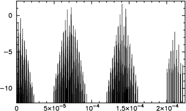
rad s-1
To characterize the Earth’s response, we should take into account that the triaxiality of the Earth’s inertia tensor is small, about . Therefore, the differential equations of the Earth’s rotation are linear. First, this leads to decoupling rotation around the axes 1 and 2, i.e. the polar motion, and rotation around the axis 3, the diurnal motion. Second, the response to harmonic external forces will result in harmonic variations of the component 2 of with the same amplitude as component 1 with the phase shifted by . Third, the excitation at the diurnal frequency will result in the appearance of cross-terms and (Moritz 1987).
Considering these factors, the following mathematical model for the the vector of a small perturbational rotation is proposed:
| (12) |
where is the B-spline function of degree determined at a sequence of knots ; are the frequencies of external forces; the coefficients ; are the parameters of the expansion, is the nominal frequency of the Earth’s rotation. Here is the dimension of the B-spline basis and is the dimension of the Fourier basis. Thus, the vector of small perturbational rotation is expanded into the basis of B-splines, which is orthogonal over the entire period of observations, and the basis of harmonic functions, which is orthogonal in the range . The first basis approximates the slowly varying component in the Earth’s rotation, the second basis approximates the quasi-diurnal component, as well as other harmonic constituents of the Earth’s rotation.
3.1 The B-spline basis
The B-spline basis functions were first introduced by Schönberg (1946). The B-spline function of degree depends on time and on a monotonically nondecreasing sequence of knots at the interval . In order to introduce splines, let us extend this sequence by adding elements at the beginning of the sequence and –1 elements at the end of the sequence such that and . At a given extended sequence of knots, B-spline functions with the pivot element are defined through a recursive relationship.
The B-spline of the 0-th degree with the pivot knot on the knots sequence , such that , is determined by
| (15) |
The B-spline of the th degree with the pivot knot on the extended sequence of knots is expressed via the B-splines of the th degree as
| (16) |
Computation of B-splines is as simple as computation of other polynomials. Similar simple recursive relationships exist for derivatives of B-splines and integrals. The B-spline of degree with the pivot element is non-zero only at the interval . It can be proved that a sequence of B-spline functions of degree with pivot elements forms a basis on the interval . The proof of this and many other useful theorems related to B-splines can be found in Nürnberger (1989).
In general, knots can be selected arbitrarily. Test runs have shown that a set of B-spline functions of the 3rd degree with equidistant knots with a time span of 3 days for components 1, 2, and 1 day for component 3 of the vector adequately represents the slowly varying component of the Earth’s rotation. Weak constraints on values of B-splines, its first and second derivatives can be imposed to ensure the stability of the solution at intervals with considerable gaps in observations and at the beginning and the end of the data set.
3.2 The Fourier basis
Modeling the quasi-diurnal components is more challenging. The tides exerted by the Moon and the Sun cause variations in sea currents and the sea surface at tidal frequencies. These variations excite changes in all components of the Earth’s rotation. The resonance near the retrograde diurnal frequency causes a significant amplification at that frequency band for components 1 and 2 of the vector . The theoretical spectrum of this motion referred to as nutation computed by Souchay & Kinoshita (1996, 1997) and Souchay et al. (1999) for the model of the rigid Earth, the REN–2000 expansion, is presented in Fig. 3.

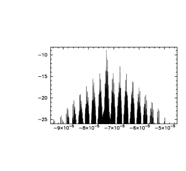
rad s-1
The problem is that the spectrum is very dense, and observations during a finite period of time cannot resolve all the constituents. The REN–2000 spectrum has 560 constituents with amplitudes greater than rad and 1551 constituents with amplitudes greater than rad with the frequency difference between some of them as low as rad s-1.
Several strategies can be used for overcoming this problem. First, we can select frequencies with maximal amplitudes from the theoretical spectrum and ignore constituents with an angular frequency separation less than , where is the interval of observations. No signal will be mismodeled if the frequency separation between the constituents , since in this case the two constituents will be indistinguishable.
However, if the constituents are not very close, the mismodeled signal will leak into adjustments at other frequencies. The sidelobe with the amplitude and frequency of the main constituent with the frequency can be omitted if the quantity is less than a certain threshold. Depending on the threshold level, there are several hundred constituents in the tidal spectrum for which this condition is not valid.
One way to mitigate this problem is to estimate the amplitude of close sidelobes, together with the amplitude of main constituents, and to impose strong constraints on the amplitude of sidelobes by using some a priori information. It is plausible to assume that the a posteriori amplitudes of constituents of the quasi-diurnal motion for the real Earth differ from the theoretical amplitudes computed for the rigid Earth by multiplicative factors called transfer function, which is a smooth function of frequency according to theory. Then we can assume that the transfer function for two close constituents with theoretical amplitudes be the same, i.e. the ratio of complex amplitudes of two close constituents is the same as for the a priori rigid Earth amplitudes, and, therefore, should satisfy this equation:
| (17) |
Although this approach reduces the leakage from a mismodeled signal, it is not fully satisfactory. In general, using strong constraints is undesirable, since this introduces a bias in estimates. The validity of Eq. 17 cannot be confirmed or refuted from observations. It comes from a theory. But if the estimation model implicitly incorporates theoretical assumptions, strictly speaking the estimates cannot be used for validation of the theory. Although Eq. 17 for EOP variations caused by the tidal potential exerted by external bodies has a sound theoretical basis, we should bear in mind that the ultimate goal of comparing theoretical predictions with observations is to check the validity of assumptions built into the foundation of the theory and to make a judgment whether the model is complete or not. If there are unaccounted additive constituents at these frequencies, for example, caused by the free motion, by the atmospheric, or by oceanic excitation, the Eq. 17 may not be valid.
An alternative to constraining sidelobes is the strategy of estimating a wide range of constituents that are multiples of or, in other words, indirectly performing the discrete Fourier transform of the perturbational rotation. With this approach, in general we are in a position to discard our a priori knowledge about the frequency structure of the signal. Estimating the signal at discrete frequencies that are multiples of , from the zero frequency through the Nyquist frequency, recovers any signal according to the sampling theorem. However, this kind of approach applied to estimating the vector has a practical value only if the number of non-negligible constituents in the discrete spectrum is significantly less than the total number of samples. Since the spectrum of the tide-generating potential consists of a set of discrete frequencies that are not commensurate to each other, the frequencies that are multiples of cannot coincide with all tidal frequencies. If the amplitude of a narrow-band harmonic signal is not estimated at its frequency, but estimated at a set of nearby frequencies that are multiples of , the signal will be recovered only partially. The wider the range of frequencies, the better the approximation. The rate of convergence depends on the amplitude of the signal and the difference between its frequency and the closest frequency used for estimation. Selection of reasonably good a priori values may significantly reduce the number of frequencies needed for estimation to reach a given level of accuracy of approximation.
Other important constituents of the signal at the retrograde diurnal band are the free near-diurnal wobble (Moritz 1987) and the atmospheric nutations (Bizouard et al. 1998; Yseboodt et al. 2002). Since this signal is excited by a broad-band stochastic process, it is expected that these constituents in the Earth’s rotation are also relatively broad-band. To model this signal, the constituents at frequencies within the range of that band need to be added to the list of constituents at tidal frequencies. It follows from the sampling theorem of Kotelnikov (1933) that a band limited signal with frequencies in the range of is completely recovered when the estimates of the sine and cosine amplitudes of the spectrum are made at discrete frequencies .
The tidal spectrum also has constituents with low frequencies, so-called zonal tides. They affect component 3 in the vector of the perturbational rotation. Their contribution dominates the rate of change for this component. It would be desirable to estimate the complex amplitude of this variations. Since the residual rate of change of is a factor of 3–10 less, constraints on a rate of change for the residual component of , modeled with an expansion over the B-spline basis can be set stronger without introducing a bias in the estimates. This improves the solution stability during intervals of time with gaps in observations. For the same reason, it would be desirable to estimate variations in components 1 and 2 of the Earth’s rotation vector at the annual and Chandler frequencies: and rad s-1 , respectively.
3.3 Decorrelation constraints
It should be noted that the estimates of harmonic constituents with lower periods than the time span between nodes of B-spline will so highly correlate with B-spline coefficients that the system of equations will be very close to singular. Decorrelation constraints on coefficients of the B-spline should be imposed in order to overcome this problem. We require that the product of expansion over basic B-spline and Fourier functions for the th frequency be zero over the interval of observations:
| (20) |
This is reduced to
| (23) |
Thus, two constraint equations for each frequency are to be imposed. The Fourier integral of a B-spline of the th degree in Eq. 23 on a knots sequence with the pivot knot such that is expressed through the Fourier integral of a B-spline of the th degree:
| (27) |
The Fourier integral of a B-spline of the 0-th degree on the same sequence with the pivot knot is
| (28) |
4 Analysis of VLBI observations
4.1 The VLBI dataset
A set of estimates of group delays at frequency bands centered around 2.2 and 8.6 GHz from January 1984 through January 2006 was used to validate the proposed approaches. The International VLBI Service for Geodesy and Astrometry (IVS) (Vandenberg 1999) provides online access to the collection of all observations made in the geodetic mode under various astrometric and geodynamics programs from 1979 through now at http://ivscc.gsfc.nasa.gov. The VLBI data set shows a substantial spatial and time inhomogeneity. Typically, observations are made in sessions with a duration of about 24 hours. Observations were sporadic in the early 80s, but in January 1984 a regular VLBI campaign for the determination of the Earth orientation parameters started first with 5-day intervals, from May 1993 with weekly intervals, and from 1997 twice a week. In addition to these observations, various other observing campaigns were running. On average, 150 sessions per year have been observed since 1984.
During that period 153 stations participated in observations, although a majority of them observed only during short campaigns. The observations at stations that participated in less than observations, and the stations that only participated in at regional networks with sizes of 2000 km and less were discarded. Forty four stations remained. Observations of sources that were observed in less than 4 sessions and gave less than 64 usable pairs of dual-band group delays were excluded. The data before January 1984 were also discarded. In total, 5% of the observations were excluded, and the remaining data from 3563 sessions between January 1984 to August 2006, more than 4.6 million of dual-band pairs of group delays, were used in the analysis.
The number of participating stations in each individual session varies from 2 to 20, although 4–7 is a typical number. No station participated in all sessions, but every station participated in sessions with many different networks. All networks have common nodes and, are therefore, tied together. Networks vary significantly, but more than 70% of them have a size exceeding the Earth’s radius.
4.2 Theoretical model
The state of the art theoretical models were used for computing the theoretical time delay and its partial derivatives. The procedure in general follows the approach presented by Sovers et al. (1998) with some minor refinements. The expression for time delay derived by Kopeikin and Schäfer (1999) in the framework of general relativity was used. The displacement caused by the Earth’s tides were computed using a rigorous algorithm Petrov & Ma (2003) with a truncation at a level of 0.05 mm using the numerical values of the generalized Love numbers presented by Mathews (2001). The displacements caused by ocean loading were computed by convolving the Greens’ functions with ocean tide models using the NLOADF algorithm of Agnew (1997). The GOT00 model (Ray 1999) of diurnal and semi-diurnal ocean tides, the NAO99 model (Matsumoto et al. 2000) of ocean zonal tides, the equilibrium model of the pole tide and the tide with period of 18.6 years were used. The atmospheric pressure loading was computed by convolving the Greens’ functions with the numerical model of the atmosphere NCEP Reanalysis (Kalnay et al. 1996). The algorithm of computations is described in full details in Petrov & Boy (2004).
The a priori path delay in the atmosphere caused by the hydrostatic component was calculated as a product of the zenith path delay computed on the basis of surface pressure using the Saastamoinen (1972) expression and the isobaric mapping function (Niell & Petrov 2004) computed using the geopotential height of the 20 kPa pressure layer provided by the numerical weather model NCEP Reanalysis. The isobaric mapping function describes the dependence of path delay on the angle between the local axis of symmetry of the atmosphere and the direction to the observed sources. The direction of this axis from the zenith was considered to coincide with the normal to the surface of the geopotential height at the 20 kPa pressure level. This normal was computed using the NCEP Reanalysis dataset.
Since the accuracy requirements to the of the a priori Earth rotation model are very low in the framework of the present approach, we can exploit this to use the simplest possible model. The following expression for the a priori matrix of the Earth’s rotation according to the Newcomb-Andoyer formalism was used:
| (31) |
where is a rotation matrix around the axis . For the variables the following simplified expressions were used:
| (41) |
Here is TAI time elapsed from 2000 January 01, 12 hours. It should be noted that expressions 41 differs from those used in the framework of the traditional approach (McCarthy & Petit, eds. 2004). Some of these parameters were taken from theory, some of them were found with the LSQ fit of time series of adjustments of pole coordinates and UT1–TAI. The numerical values of parameters used in data analysis are presented in the online Tab. 3. The rms of the adjustments of the perturbational vector of the Earth rotation with respect to the a priori matrix presented in expressions 31 and 41 over the period of 1984–2006 was less than rad for each component.
4.3 Basic estimation model
Several solutions were produced. Each solution used the basic parameterization which was common for all runs, and a specific parameterization for an individual solution. Basic parameters belong to one of the three groups:
-
—
global (over the entire data set): positions of 598 sources and proper motions of 169 sources; positions and velocities of 44 stations; coefficients for the expansion into B-spline basis of positions of 7 stations, DSS15, DSS65, GILCREEK, HRAS_085, MEDICINA, MOJAVE12, PIETOWN, (Petrov 2005); coefficients for harmonic position variations of all sites at the annual and the semi-annual frequency (Petrov & Ma 2003); coefficients of the B-spline for modeling the perturbational Earth’s rotation vector at a set of equidistant knots with a time span of 3 days for components 1 and 2 and with a time span of 1 day for component 3.
-
—
local (over each session): tilts of the local symmetric axis of the atmosphere for all stations and their rates, station-dependent clock functions modeled by second order polynomials, baseline-dependent clock offsets.
-
—
segmented (over 0.33–1.0 hours): coefficients of linear spline that models atmospheric path delay (0.33 hour segment) and clock function (1 hour segment) for each station. The estimates of clock function absorb uncalibrated instrumental delays in the data acquisition system.
The rate of change for the atmospheric path delay and clock function between two adjacent segments was constrained to zero with weights reciprocal to and , respectively, in order to stabilize solutions. Strong no-net-translation and no-net-rotation constraints were imposed on the adjustments of site positions and velocities, as well as no-net-rotation constraints were imposed on adjustments of source positions and proper motions, in order to solve the LSQ problem of incomplete rank. Weak stabilizing constraints were imposed on B-spline coefficients to constrain to zero , its first and second derivatives at each knot. The reciprocal weights of constraints for the values of , components 1 and 2 were rad; the reciprocal weights for the first time derivatives were rad s-1, and for the 2nd derivatives rad s-2. The reciprocal weights in , , for component 3 were rad, rad s-1, and rad s-2.
4.4 VLBI solutions
Several solutions have been computed with different a priori vectors of the perturbational rotation and with a different set of harmonic constituents of the vector .
In solution A, the a priori vector was set to zero. A set of sine and cosine amplitudes of the perturbational rotation vector was estimated as global parameters. The frequencies of these estimates were selected according to the following process. First, the frequencies for components 1 and 2 of this vector in the range of the near-diurnal retrograde wobble and hypothetical near-diurnal prograde wobble (see, for instance, Dehant (1993)) were sampled with step . This step of frequency sequences corresponds to where is the interval of observations, 22.6 years. Then the frequencies of constituents with the amplitudes exceeding in the REN–2000 expansion were added to the list of constituents in order of decreasing their amplitudes, provided the minimal difference in the frequencies of the constituents was less than . If two constituents have difference in frequencies less than that, the constituent with smaller amplitude was discarded.
Second, all constituents at positive and negative diurnal, semi-diurnal, and ter-diurnal bands of the tide-generating potential with amplitudes greater than 0.003 of the amplitude of the tide were selected. At negative frequencies, all three components of the vector were estimated, while only the components 1 and 2 were estimated at positive frequencies. The same rejection criteria for the constituents with close frequencies was enforced.
Third, the harmonic signal in components 1 and 2 of at the Chandler and annual frequencies, and the harmonic signal in the component 3 at 14 frequencies of zonal tides with amplitudes greater than 3% of the amplitude of the tide generating potential at the Mf frequency rad s-1 were estimated. Decorrelation constraints were imposed on estimates of B-spline coefficients.
Solution B is similar to solution A, but constituents at the 76 frequencies that have a close companion, a sidelobe, and that satisfy the criteria in Sect. 3, , were not rejected as in solution A, but remained on the list. Strong constraints with reciprocal weight in the form of Eq. 17 were imposed. The purpose of this solution was to investigate the effects of omitted sidelobes.
A family of solutions C was computed. The purpose of this solution was to evaluate a harmonic signal at non-tidal frequencies. In addition to the frequencies used in the solution A, a possible non-tidal signal was sought in eight frequency bands at the frequencies equally sampled with the step . The low and high edges of each frequency band are shown in Tab. 1. The total number of constituents of the perturbational rotation vector estimated for components 1 and 2 was 20 093 and and for component 3 was 9885. Since the total number of global parameters was at a level of 70 000, well beyond the capabilities of a personal computer, 20 individual solutions were performed. In each individual solution of family C, the sine and cosine amplitudes of constituents at frequencies were estimated. The estimates of constituents are correlated at a level of 0.02–0.20, since other common parameters were estimated, such as source coordinates and station positions. Strictly speaking, the procedure of estimating the spectrum by parts is not perfectly correct. But it was assumed that such a procedure may result in a false detection, but not miss the signal present in the data. In the final run of a solution of family C, 680 non-tidal frequencies were selected. The signal was detected at a 95% confidence level at these frequencies in the previous runs.
| Frequency band | Components | |
|---|---|---|
| low | high | |
| 1, 2, 3 | ||
| 1, 2, 3 | ||
| 1, 2, 3 | ||
| 1, 2, 3 | ||
| 1, 2 | ||
| 1, 2 | ||
| 1, 2 | ||
| 1, 2 | ||
The purpose of solution D was to investigate whether the process of frequency selection for solution A picked up all the signals in the diurnal band. In this solution the a priori vector was generated from the REN–2000 nutation expansion. It had all the constituents with amplitudes greater than rad, except the constituents with frequencies , , and rad s-1, because they had already been included in the matrix . For selection of the frequencies, at which the harmonics of the perturbational rotation vector was to be estimated, the time series of on the interval [1984.0, 2006.6] with a step of 0.125 days were produced, and its power spectrum was computed. Here is the vector of the adjustments of perturbational rotation in solution B and vectors , where are the a priori perturbational vectors used. The frequencies of constituents run from 0 through with step . Not all of them were estimated, but only those that had the frequency by module less than and that satisfied one of the three conditions: a) to be in the range for taking the near-diurnal wobble and the signal excited by the atmosphere into account, or b) to have the square root of the power greater than rad for taking the signal at tidal frequencies into account, or or c) to be in the range of non-tidal frequencies identified in solutions C. In total, 3676 parameters at 1706 frequencies, which are a multiple of the frequency , were selected.
The software Calc/Solve was used for these solutions. Results of analysis are available on the Web at http://vlbi.gsfc.nasa.gov/erm.
5 Discussion of results
5.1 Differences with respect to the traditional approach
Analysis of the results showed that the approach for the direct estimation of the perturbational rotation vector in the form of expansion into basic functions from VLBI observations allows us to represent the Earth’s rotation adequately. The fit of the least square solutions, 21.9 ps, was the same as the fit in solutions that followed the traditional time series approach. The slowly varying component was compared with the USNO EOP model. The USNO Finals EOP time series with 1 day steps was derived by averaging results of analysis of GPS and VLBI observations and smoothing. To compare results, the USNO series of polar motion, , and UT1–TAI with respect to the a priori Earth rotation model in expressions 41:
| (46) |
where , and parameters are from expressions 41. The coefficients of the interpolation spline for were computed. These coefficients form the USNO Earth rotation model as a continuous function of time. Since the GPS results almost entirely dominate components 1 and 2 of the Earth rotation vector from that model, they can be considered independent from our analysis of VLBI observations.
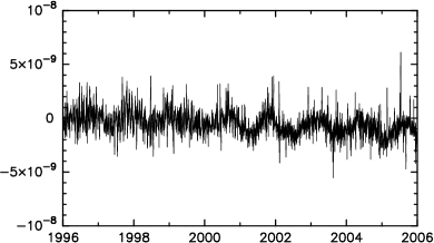
The differences for component 1 between the USNO model and our results from solution B after removal the contribution of harmonic variations with periods less than 2 days are shown in Fig. 4. No pattern of systematic differences is revealed. The statistics of these differences for all three components of the small vector of the Earth rotation and their time derivatives computed at the equidistant grid with time interval 2.5 hours are presented in the 1st row of Tab. 2.
Since the VLBI observations are not carried out continuously due to budget limitations, the accuracy of the Earth orientation model is the highest within an interval of observations and the lowest at moments of time when there were no observations. In the framework of the traditional approach, the EOP are estimated on moments of time in the middle of a 24 hour observing session. The statistics of the differences of the EOP series from analysis of VLBI observations gsf2006c333Available on the Web at http://vlbi.gsfc.nasa.gov/solutions/2006c for moments in the middle of 1426 observing sessions are shown in the 3rd row of Tab. 2. For comparison, the EOP were computed from results of solution B at exactly the same epochs, and these statistics of the differences with respect to the USNO model are presented in the 2nd row of this table.

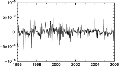
Time in years
| Solution | ||||||
|---|---|---|---|---|---|---|
| ERM all | rad | rad | rad | rad s-1 | rad s-1 | rad s-1 |
| ERM exp | rad | rad | rad | rad s-1 | rad s-1 | rad s-1 |
| gsf2006c | rad | rad | rad | rad s-1 | rad s-1 | rad s-1 |
Analysis of statistics shows that the differences in components 1 and 2 of the Earth’s orientation according to the proposed and traditional approaches do not exceed 20%. At the same time the proposed approach gives the estimates of all the components of the Earth’s angular velocity vector by a factor of 1.5–2.0 closer to the GPS results than the estimates produced in the framework of the traditional approach. According to the traditional approach, the EOP rates and nutation daily offsets are computed for each session independently, which makes them less stable. With the proposed approach, at a given epoch several experiments contribute to estimates of EOP rate, which makes them more robust.
Analysis of the differences in amplitudes of the harmonic terms of components 1 and 2 of the vector of perturbational rotation at the retrograde diurnal band with respect to the semi-empirical MHB2000 expansion (Mathews et al. 2002), showed they can reach 0.2 nrad for some terms. Detailed analysis of these differences is beyond the scope of the present paper. In order to test results, the empirical Earth rotation model from solution B was used as the a priori for the solution that estimated the time series of daily offset to nutations. The weighted root mean square of the differences for the period of [1996.0, 2006.0] is 0.39 nrad when results of solution B were used as the a priori, and 0.98 nrad when the MHB2000 was used. The daily offsets to nutation in obliquity with respect to both models are shown in Figs. 5–6.

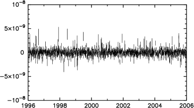
Time in years

Time in years
5.2 Harmonic components in the Earth’s rotation
Analysis of estimates of the harmonic components showed excessive power near the frequency of the near-diurnal retrograde wobble, as was expected. The spectrum turned out rather broad, spanning a rather wide band, and it partly overlaps with the tidal frequency that corresponds to the annual retrograde nutation as shown in Fig. 7. It was found by Herring et al. (1986) that the near-diurnal wobble cannot be represented by a purely harmonic model with a constant amplitude. This means that when this component of the Earth’s rotation is represented in the frequency domain, several constituents in the spectrum will correspond to it.

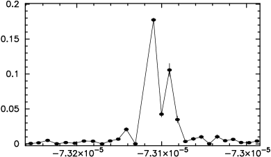
rad s-1
Analysis of the results of the C family solutions revealed several constituents with the non-tidal signal. The spectrum of components 1 and 2 in the vicinity of the frequency , i.e. the tide, turned out rather broad. The excerpt of the power spectrum produced from estimates of sine and cosine amplitudes of the components 1 and 2 is shown in Fig. 8. This signal cannot be attributed to the spectral leakage, since no excessive power was found in the vicinity of even a stronger tide at the frequency. A relatively broad-band signal in the vicinity of the frequency, i.e. , was found at the 3rd component of the rotation vector. The excerpt of the power spectrum produced from estimates of sine and cosine amplitudes of the component 3 is shown in Fig. 9. A weaker signal in the estimates can also be revealed in the vicinity of the frequency. A similar signal can be seen at prograde frequencies in the vicinity at components 1 and 2444Since component 3 was considered as a real value process, its spectral power at negative frequencies is the same as at positive frequencies..
Another peculiarity of the spectrum are sharp peaks at frequencies at a level of 2–7 above the noise level. No convincing explanation was found, but it is suspected that this signal in the estimates may be an artifact caused by errors in modeling by analogy with a detection of a very strong signal in estimates of the harmonic constituents of the perturbational Earth’s rotation from GPS time series at frequencies that are multiple to the diurnal frequency: , etc., reported by Rothacher et al. (2001). It should be noted that no non-tidal signal at frequencies is seen from analysis of VLBI group delays.

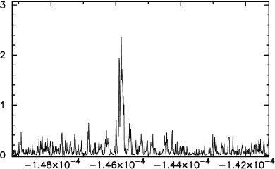
rad s-1

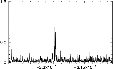
rad s-1
Solution D did not reveal other missed harmonic signals in the diurnal band.
5.3 Error analysis
The formal uncertainties of the amplitudes on harmonics constituents can be evaluated on the basis of the signal-to-noise ratio of fringe phases used for computing group delay by invoking the law of error propagation. These uncertainties are in a range of 5–12 prad. Analysis of the estimates of the constituents at the frequency bands where no tidal or no-tidal signal was detected provides a more reliable measure of noise in adjustments. It is 16 prad for components 1,2 and 13 prad for component 3 for the diurnal band; 13 prad and 10 prad for these components at other frequency bands. This corresponds to displacements of 0.06–0.12 mm at the Earth’s surface. Evaluation of the level of systematic errors is more problematic. The major possible source of systematic errors is considered to be a residual motion of the individual stations. In fact, the rotation of the station polyhedron was evaluated, and it was assumed that the motion of this polyhedron is a representative measure of the Earth’s rotation. This assumption is valid to the extent that residual horizontal motion of individual observing stations is negligible. Petrov & Ma (2003) estimated harmonic site position variations and found that the accuracy of modeling the horizontal motion of individual stations is at the level of 0.4 mm. In the case of the errors of modeling being completely uncorrelated, this error will be diluted as , where is the effective number of observing stations, 10–44, depending on how to define the effective number of stations. Unfortunately, the distribution of residual motions of stations at tidal frequencies shows a pattern of a systematic behavior, which does not support the hypothesis of uncorrelated errors. A conservative estimate of the possible contribution of the unmodeled residual motion of the network of stations to the estimates of harmonic constituents of the perturbational rotation suggests a dilution factor of 2, i.e. the surface displacements mm. That means systematic errors may be two times greater than random errors.
Dehant et al. (2003) investigated the influence of systematic errors due to the neglect of the modeling source structure. It was suggested to split the observed radio sources into two classes, “stable” and “unstable”, and either to remove unstable sources from analysis or to estimate the time series of their positions. In this paper a different approach was used: proper motion of those sources that had a long enough history of observations was estimated. This method is supposed to reduce systemic errors in the estimates of the harmonic constituents in the perturbational rotation vector.
6 Conclusion
It was demonstrated that the empirical Earth rotation model can be determined directly from observations over a period of 22 years using the least square estimation technique. The advantage of the proposed approach is that a continuous function describing the Earth’s orientation is determined in one step without producing intermediate time series. The consistency between station positions, source coordinates, and the empirical Earth rotation model is automatically achieved. Another advantage of the proposed approach is that a simplified a priori model with only 31 numerical parameters is sufficient, while the traditional approach needs a complicated a priori model of precession, nutation, high frequency harmonic variations of the Earth’s rotation, and a filtered and smoothed time series of the Earth orientation parameters produced in the previous analysis, in total numerical parameters (McCarthy & Petit, eds. 2004).
The traditional approach to describing the Earth’s rotation follows the formalism of either Newcomb and Andoyer or Guinot (1979) and Capitaine et al. (1986), and involves such notions as the celestial intermediate pole, the point of the vernal equinox, the non-rotating origin, the ecliptic, and other axes, points, planes, and circles on the celestial sphere. The advantage of the empirical Earth rotation model is that it is conceptually simpler, since it is built entirely kinematically and does not require introduction of intermediate points, axes, planes that are not observable.
It was demonstrated that the empirical Earth rotation model derived from analysis of VLBI observations gives the differences with respect to the EOP derived from analysis of independent GPS observations at moments of observation at the same level, within 20%, as the differences of the VLBI EOP series produced with the traditional approach. The advantage of the proposed approach is that the estimates of the EOP rates are a factor of 1.5–2.0 closer to the GPS time series than the VLBI EOP rates estimated following the traditional approach.
When results of analysis of observations are compared with theoretical predictions, two approaches can be taken: a) the parameters that describe empirical data are formulated through parameters of the theoretical models; b) theoretical predictions are transformed to a form that can be unambiguously determined from the observations. Representation of the Earth’s rotation in the form of the expansion into basis functions establishes a foundation for the second approach.
Scientific interpretation of the results of estimation of the empirical Earth rotation model will be given in the next paper.
Acknowledgements.
This work was done while the author worked at the National Observatory of Japan, Mizusawa, as a visiting scientist. The author would like to thank S. Manabe, T. Sato, Y. Tamura, D. Rowlands, Ch. Bizouard and an anonymous referee for useful discussion that helped to improve the manuscript.References
- Agnew (1997) Agnew, D. C., 1997, J. Geophys. Res., 102, 5109
- Aoki (1982) Aoki, S., Kinoshita, H.; Guinot, B., 1982, å, 105, 359
- Bizouard et al. (1998) Bizouard C., Brzezinski, A., Petrov S., 1998, J. of Geodesy, 72, 561
- Capitaine et al. (1986) Capitaine, N., Guinot, B., & Souchay, J., 1986, Celest. Mech., 39, 283
- Dehant (1993) Dehant, V., 1993, Adv. Space Res., 13, 235
- Dehant et al. (2003) Dehant, V., Feissel-Vernier M., de Viron O. et al., 2003, J. Geophys. Res., 108, 2275
- Dickman (1993) Dickman, S. R, 1993, Geophys. J. Int., 112, 448
- Dick and Richter (2004) Dick W. R. and B. Richter ed., 2005, IERS Annual Report 2004 of the International Earth Rotation and Reference Systems Service, Frankfurt am Main: Verlag des BKG, 152 p.
- Eubanks (1993) Eubanks, T. M., 1993, Contributions of Space Geodesy to Geodynamics: Earth Dynamics: Geodynamics Series, vol. 24, ed. by D. E. Smith & D. L. Turcotte, AGU
- Getino & Ferrandiz (2001) Getino J. & Ferrandiz J. M., 2001, MNRAS, 322, 785
- Guinot (1979) Guinot, B. 1979, In Time and the Earth’s Rotation, ed. McCarthy D. D., & Pilkington, J. D. (D. Reidel Publishing Company), 7
- Herring et al. (1986) Herring, T. A., Gwinn, C. R. & Shapiro, I. I., 1986, J. Geophys. Res., 91, 4745
- Kalnay et al. (1996) Kalnay E., M. Kanamitsu, R. Kistler, et al., 1996, Bullet. Amer. Meteorol. Soc., 77, 437
- Kopeikin and Schäfer (1999) Kopeikin, S. M. and Schäfer, G., 1999, Phys. Rev. D, 124002
- Kotelnikov (1933) Kotelnikov, V. A., 1933, In Proceedings Materialy k I vsesouznomu s’ezdu po voprosam technicheskoj rekonstruktcii dela svyazi i razvitija slabotochnoj promyshlennosti
- Mathews et al. (1991) Mathews, P. M., Buffett, B. A., Herring, T. A. & Shapiro, I. I., 1991, J. Geophys. Res., 96, 8219
- Mathews (2001) Mathews, P. M., 2001, Journal of the Geodetic Society of Japan, 47, 231
- Mathews et al. (2002) Mathews P. M., Herring, T. A., & Buffett B. A., 2002, J. Geophys. Res., 107, 10.1203/2001JB1000390
- Matsumoto et al. (2000) Matsumoto, K., T. Takanezawa, & M. Ooe, 2000, Journal of Oceanography, 56, 567
- McCarthy & Petit, eds. (2004) McCarthy D. & G. Petit, eds., IERS Conventions, 2004, Verlag des Bundesamtes fuer Katrografie und Geodaesie, 127
- Moritz (1987) Moritz H., Earth Rotation: Theory and Observation, 1987, Frederick Ungar, 617
- Niell & Petrov (2004) Niell, A & Petrov L., 2004, In Proceedings of the workshop ’The State of GPS Vertical Positioning Precision: Separation of Earth Processes by Space Geodesy’, ed. by T. van Dam and O. Francis, Luxembourg, 55
- Nürnberger (1989) Nürnberger, G., 1989, Approximation by spline functions, Springer-Verlag
- Petrov & Ma (2003) Petrov L., & C. Ma, 2003, J. Geophys. Res., 108, doi: 10.1029/2002JB001801, 2190
- Petrov & Boy (2004) Petrov L., & Boy, J.-P. 2004, J. Geophys. Res., 109, 10.1029/2003JB002500, B03405
- Petrov (2005) Petrov L., 2005, In Proceedings of the 17th working meeting on European VLBI for geodesy and astrometry, ed. by M. Vennenbusch & A. Nothnagel, 113
- Ray (1999) Ray, R. D., 1999, NASA/TM-1999-209478, 58
- Rothacher et al. (2001) Rothacher, M., G. Beutler, R. Weber, and J. Hefty, 2001, J. Geophys. Res., 106, 13,711
- Saastamoinen (1972) Saastamoinen, J., 1972, In The Use of Artificial Satellites for Geodesy, Geophys. Monogr., AGU, 15, 247
- Schönberg (1946) Schönberg, I. J., Contributions to the problem of approximation of equidistant data by analytic functions, 1946, Quart. Appl. Math., 4
- Seidelmann (1992) Seidelmann, P. K., 1992, Explanatory Supplement to the Astronomical Almanac
- Simon et al. (1994) Simon, J. L. & Bretagnon, P., Chapront, J. & Chapront-Touze, M., 1994, A&A, 282, 663
- Souchay & Kinoshita (1996) Souchay J. & Kinoshita H., 1996, A&A, 312, 1017
- Souchay & Kinoshita (1997) Souchay J. & Kinoshita H., 1997, A&A, 318, 639
- Souchay et al. (1999) Souchay J., Loysel B., Kinoshita H., and Folgueira M., 1999, A&AS, 135, 111
- Sovers et al. (1998) Sovers, O. J, J. L. Fanselow, and C. S. Jacobs, 1998, Review of Modern Physics,70, 1393
- Vandenberg (1999) International VLBI Service for Geodesy and Astrometry, 1999 annual report, ed. N. Vandenberg, NASA/TP-1999-209243, Greenbelt, 308
- Wahr (1980) Wahr, J. M., 1981, Geophys. J. R. Ast. Soc., 64, 705
- Yseboodt et al. (2002) Yseboodt, M., de Viron O., Chin T. M., & Dehant V., 2002, J. Geophys. Res., 107, 2036, doi:10.1029/2000JB000042
| Var | Value | Units | Source |
|---|---|---|---|
| rad | Simon et al. (1994) | ||
| Simon et al. (1994) | |||
| Simon et al. (1994) | |||
| rad | Simon et al. (1994) | ||
| Simon et al. (1994) | |||
| Simon et al. (1994) | |||
| rad | Simon et al. (1994) | ||
| Simon et al. (1994) | |||
| Simon et al. (1994) | |||
| rad | Simon et al. (1994) | ||
| Simon et al. (1994) | |||
| Simon et al. (1994) | |||
| rad | Aoki (1982) | ||
| Aoki (1982) | |||
| rad | Souchay & Kinoshita (1996) | ||
| rad | Souchay & Kinoshita (1996) | ||
| rad | Souchay & Kinoshita (1996) | ||
| rad | Souchay & Kinoshita (1996) | ||
| rad | Simon et al. (1994) | ||
| rad | Simon et al. (1994) | ||
| Simon et al. (1994) | |||
| Simon et al. (1994) | |||
| rad | LSQ fit | ||
| LSQ fit | |||
| LSQ fit | |||
| rad | Dickman (1993) | ||
| rad | Dickman (1993) | ||
| rad | LSQ fit | ||
| rad | LSQ fit | ||
| Dickman (1993) | |||
| LSQ fit |