Spin-Kick Correlation in Neutron Stars: Alignment Conditions and Implications
Abstract
Recent observations of pulsar wind nebulae and radio polarization profiles revealed a tendency of the alignment between the spin and velocity directions in neutron stars. We study the condition for spin-kick alignment using a toy model, in which the kick consists of many off-centered, randomly-oriented thrusts. Both analytical considerations and numerical simulations indicate that spin-kick alignment cannot be easily achieved if the proto-neutron star does not possess some initial angular momentum, contrary to some previous claims. To obtain the observed spin-kick misalignment angle distribution, the initial spin period of the neutron star must be smaller than the kick timescale. Typically, an initial period of a hundred milliseconds or less is required.
1 Introduction
It is well known that pulsars have much larger space velocities than their progenitors, implying a kick at neutron star (NS) birth (e.g., Lorimer et al. 1997; Arzoumanian et al. 2002; Chatterjee et al. 2005; Hobbs et al. 2005; Winkler & Petre 2006). The physical mechanism for the kick, however, remains unclear (e.g., Lai 2004; Janka et al. 2005). One of the reasons that it has been difficult to constrain various kick mechanisms is the lack of correlations between kick velocity and the other properties of NSs. This situation has been changed due to the recent high-resolution Chandra X-ray observations of pulsar wind nebulae (e.g., Pavlov et al. 2000; Helfand et al. 2001; Ng & Romani 2004), which provided the evidence for spin-kick alignment for several young pulsars (e.g, Lai et al. 2001; Romani 2004; Wang et al. 2006)111A recent re-analysis of the proper motion of the Crab pulsar (Ng & Romani 2006) indicates that the spin-kick misalignment angle is .
Another well-known method to determine the spin axis of pulsars is by the linear polarization profile of radio emission. If the polarization profile could be described by rotating vector model (RVM), one can constrain the projected spin axis by the polarization angle at the center of the pulse. Previous attempts using this method have yielded ambiguous results (e.g., Morris et al. 1979; Anderson & Lyne 1983; Deshpande et al. 1999) mainly because for many pulsars the polarization profiles are not well described by the RVM (Weisberg et al. 1999). With Parkes surveys (e.g., Manchester et al. 1996, 2001), many well-calibrated polarization profiles became available, and more pulsar rotation measures to eliminate the Faraday rotation effect (e.g. Han et al. 2006). Moreover, proper motions for more than 200 pulsars have been determined (Hobbs et al. 2005). By selecting pulsars with well calibrated polarization and proper motion measurements, Wang et al. (2006) have obtained spin-kick misalignment angle for 24 pulsars, and the data revealed a strong tendency of spin-kick alignment. Johnston et al. (2005) independently obtained similar results for 25 pulsars based on different sample.
On the other hand, one can constrain NS kicks using the orbital properties of NS binary systems (e.g., Dewey & Cordes 1987; Fryer & Kalogera 1997; Willem et al. 2004; Thorsett et al. 2005). In Wang et al. (2006), we obtained constraints on the kick magnitudes and directions for various NS binaries, including double NS systems, binaries with massive main-sequence companions, and binaries with massive white-dwarf companions. We found that the kick velocity is misaligned with the NS spin axis in a number of systems, and the NS spin period (when available) in these systems is generally longer than several hundreds milliseconds.
What is the implications of the apparent spin-kick alignment for many pulsars? One possibility which is widely discussed (e.g., Johnston et al. 2005) comes from Spruit & Phinney (1998). They suggested that the initial spin of NS may originate from off-centered kicks even when the proto-NS has no angular momentum. They further suggested that if one imagine that the kick is composed of many random thrusts, then with multiple thrusts, alignment may be easily achieved.
In this paper, we systematically study the condition of spin-kick alignment using a toy model similar to that of Spruit & Phinney (1998). We consider both the cases of zero and finite initial proto-NS spin. In §2 we introduce our toy model for kicks and describe our simulation procedure. In §3 we derive approximate but analytic conditions for spin-kick alignment. In §4, we present our simulation results (especially the distribution of spin-kick misalignment angle) under different initial conditions. We find that, consistently with our analytical estimate, without initial spin of the proto-NS, it is difficult to achieve spin-kick alignment. This is contrary to some previous claims (e.g., Spruit & Phinney 1998; Johnston et al. 2005). However, with sufficiently short initial spin period (less than the timescale for each kick thrust), spin-kick alignment can be achieved. We discuss the implications of our results in §5.
2 A Toy Model for Kicks
The basic equations governing the evolution of the center-of-mass velocity and angular velocity of a proto-NS (mass , radius ) are
| (1) | |||||
| (2) |
Here is the kick force, and specifies the location where the force is applied, is the angular momentum, with the moment of inertia. We adopt , and .
We model the kick force on the NS as consisting of thrusts, , , each has a duration . During each thrust, we construct a “temporary” body frame (xyz) corotating with the star so that is constant in this frame (see Fig. 1). We specify the kick force by the magnitude (, the same for all thrusts) and two angles . We choose (, ) randomly distributed in the range of of and . Each thrust acts at the position , which is specified by the spherical coordinates in the nonrotating frame (XYZ) at the beginning of the thrust. Note that choosing a different range of is equivalent to choosing different , as long as remains the same. During the course of each thrust (duration ), the changes in the XYZ frame as the body rotates. In our simulation, we assume is the same for all thrusts. Thus the total kick time is . We set the total momentum at the fixed range in all simulations. We fix for all thrusts. For , we consider two possibilities: (i) The kick position is randomly distributed on a sphere in the XYZ frame; (ii) The kick position is randomly distributed on a sphere in the body frame of the NS. Our simulation results reported in §4 refer to the first case. We have found that the results of the second case are similar.

For each thrust, and are fixed in the the “temporary” body frame, i.e., , and . To find the components of the force and torque in the inertial frame (XYZ), we need to solve for the time evolution of the body axes (, or ). The (XYZ) frame and (xyz) frame are related by the rotation matrix :
| (15) |
So we have the expressions of the body axes in the (XYZ) frame:
| (25) |
At the beginning of each thrust
| (29) |
The body axis evolves according to
| (30) |
Substituting Eq. (25) in Eq. (30), we obtain the evolution of each component of , e.g., , et al., where are the three components of in the XYZ frame.
Using Eqs. (1) – (30), we can directly simulate the movement and the rotation of the NS. Consider a star with initial velocity and angular velocity . Suppose it receives a thrust at a random position with duration . We use the 4th order Runge-Kutta method to integrate equations (1), (2) and (30) to obtain and , the velocity and rotation rate after the first thrust. If the star receives a new thrust, we just select a new body frame according to the new position of the thrust, considering and as the initial velocity and angular velocity, and repeat the calculation as in the first thrust and so on.
3 Analytic Consideration
Consider a proto-NS without initial spin. The kick consists of thrusts, each with the same duration . We assume in this section. After the first thrust, the star receives an angular velocity
| (31) |
and a velocity not more than . Note that after the first thrust, the star’s spin is always perpendicular to its velocity . If the duration of each thrust is larger than the spin period caused by the first thrust, i.e.
| (32) |
then the second thrust will be rotationally averaged such that the net thrust will be along (the unit vector along ). similar argument applies to additional thrusts. The final characteristic velocity and angular velocity are given by
| (33) |
| (34) |
The typical final velocity and angular velocity are aligned, with
| (35) |
Equation (32) is a sufficient condition for spin-kick alignment but not a necessary one. It’s convenient to define a critical ratio
| (36) |
For or , spin-kick alignment may or may not be achieved. If or , different thrusts add up in a random walk fashion. The final spin and kick are of order
| (37) |
with random angle between the spin and kick.
For , or , the situation is more complicated. For the first thrusts (, 2, …, ), the thrust duration satisfies , thus the characteristic velocity and rotation rate are
| (38) |
with random directions between and . For the remaining thrusts (, , …, ), , so that rotationally averaging is effective. The final velocity and angular velocity are
| (39) | |||||
| (40) |
Here has random direction compared to . So spin and kick will be aligned when , which means
| (41) |
Otherwise, spin and kick will be misaligned.
To summarize, spin-kick alignment/misalignment depends on the critical ratio (see Eq. 36). Let , , we find
| (42) |
where we have used , , and . For
| (43) |
spin and kick will be aligned, while for , spin and kick will be misaligned.
If the NS has initial spin , the sufficient alignment condition, equation (32), should be modified to
| (44) |
4 Simulation Results
In our model, the key parameters are and or , as well as the initial spin period . Depending on the kick mechanisms, the total kick duration ranges from to a few seconds (e.g., Lai et al. 2001; Socrates et al. 2005; Scheck et al. 2006; Burrows et al. 2006a, b). Note that we choose in the range of and other parameters such that the final distributions of kick velocity and spin period of NSs qualitatively agree with observations (see Hobbs et al. 2005).
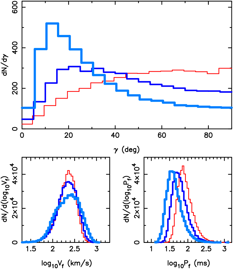
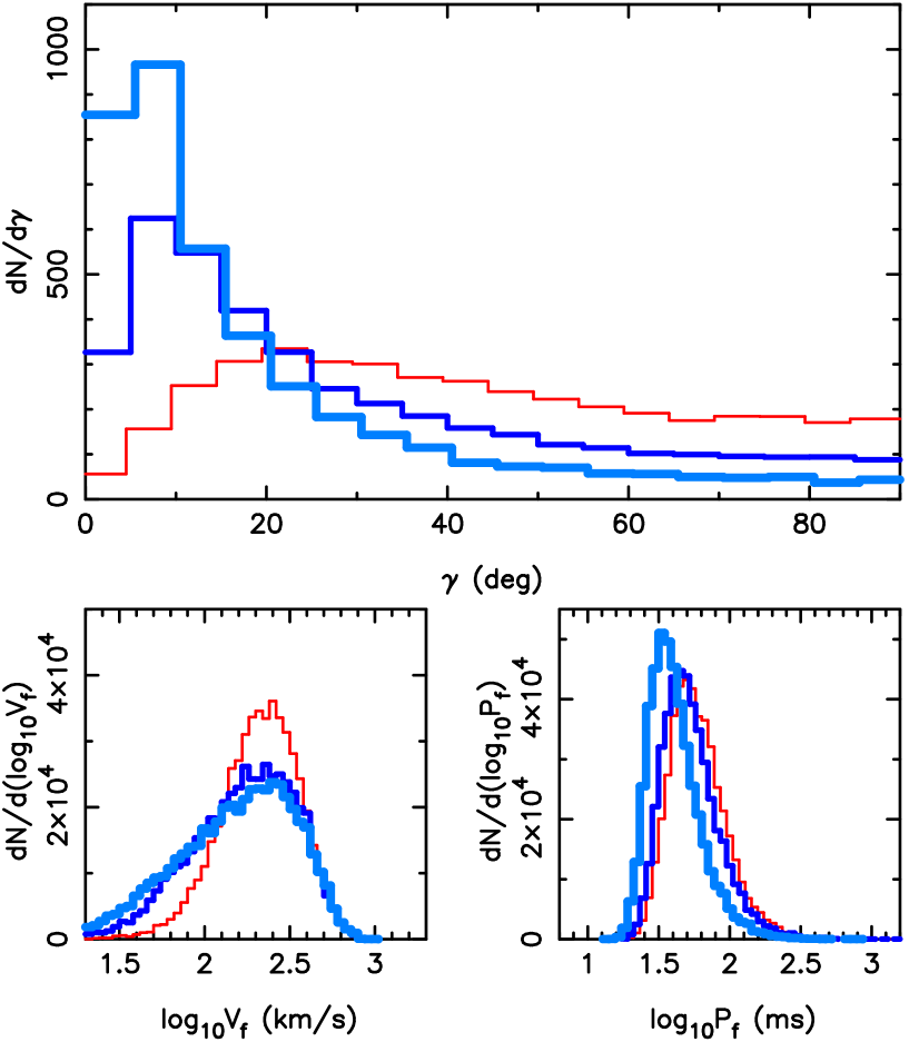
In Fig. 2 – 4, we present simulations of 20000 pulsars without initial spin (). The final spins of the NSs are all due to the off-centered thrusts. In Fig. 2, we fix the total kick duration to s, while changing the number of thrusts: , 10, 20. For these cases, (see Eq. 43). We find that an aligned distribution is produced for , but not for or 20.
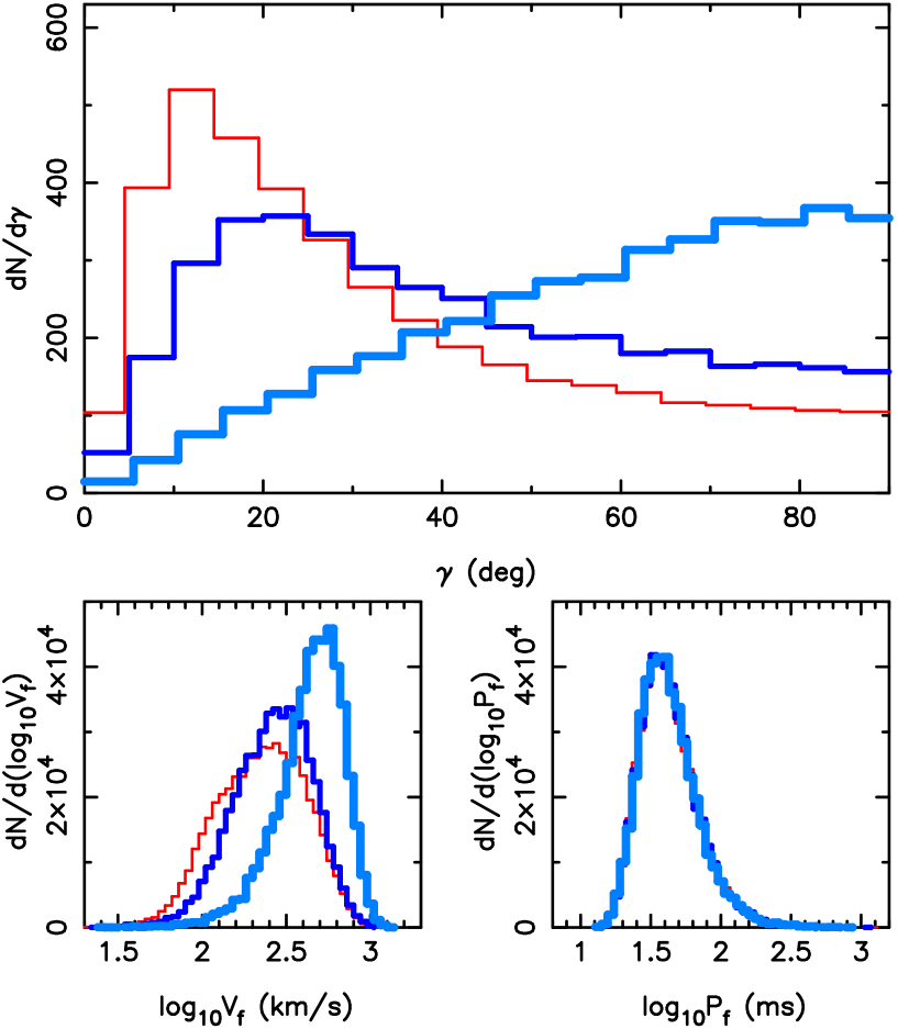
In Fig 3, we consider different values of total kick duration s, 0.5 s, 1 s, while fixing the number of thrusts to . For these cases, . So we find that for large , an aligned distribution is produced.
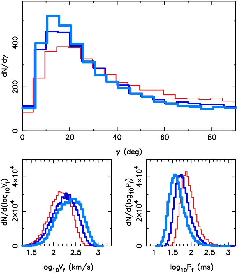
Figure 4 shows the cases with the same thrust duration s, while the number of thrusts are . Here (where ). Since either or is satisfied for these cases, the distributions all show an tendency of alignment.
Note that in the above three figures, the kick velocities are all distributed at a few hundred kilometers per second and the final spin periods are distributed from 10 to hundreds of milliseconds, in agreement with observations. Although an aligned distribution can be produced under certain conditions (see Eq. 43) without initial spin, the distributions are significantly broader than what was observed (Johnston et al. 2005; Wang et al. 2006; see Fig. 5).
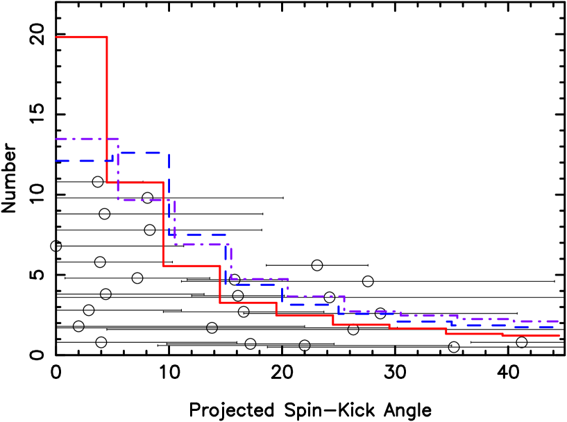
Figure 6 shows the simulations with different initial spin period ms, 100 ms and 50 ms, all with s and . Clearly, for , rotational averaging is effective, and spin-kick alignment is easily achieved. Figure 5 compares our simulation results with the observed spin-kick misalignment angles based on pulsar polarization profiles (see Wang et al. 2006), taking into account of the sky projection effect. We see that for the ms simulation depicted in Fig. 6, the simulated spin-kick distribution agrees with observational data. With ms (other parameters being the same), the simulated distribution is broader than the data. The key condition for producing alignment is Eq. (44).
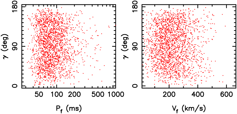
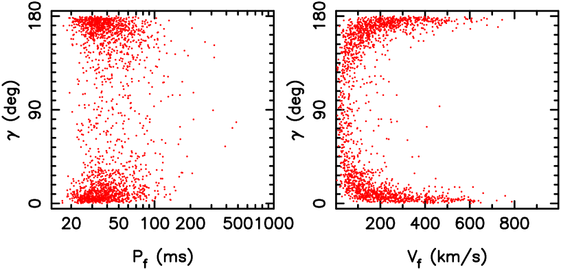
Figures 7 and 8 show the distribution of the misalignment angle as a function of and . We see that when the distribution is broad (Fig. 7), pulsars with different ’s have similar range of ’s. On the other hand, based on our toy model simulations, for an aligned distribution (Fig.8), high- pulsars have a strong tendency for spin-kick alignment. We have attempted to test such correlation in the existing sample for 24 pulsars. The current data does not show such correlation, probably because of the small sample or large error in various measurements.
5 Conclusion
In this paper, we have developed a toy model to study the conditions for pulsar spin-velocity alignment in supernova kicks. We have focused on the idea (Spruit & Phinney 1998) that multiple off-centered thrusts to the proto-neutron star may result in spin-kick alignment. We found that without initial angular momentum, the alignment cannot be easily produced. To obtain the observed spin-kick alignment distribution based on radio pulsar polarization data (Johnston et al. 2005; Wang et al. 2006), the proton-neutron stars should have appreciable rotation rate, with period less than the timescale of each kick thrust. The typical initial period required is ms.
Currently, the most conservative (and promising) kick mechanisms are “hydrodynamically driven kicks”. In particular, large-scale convections, instabilities or wave modes developed in the neutrino-heated mantle behind the shock and in the proto-neutron star may naturally lead to asymmetric explosion (e.g., Thompson 2000; Scheck et al. 2004,2006; Blondin & Mezzacappa 2006; Foglizzo et al. 2005; Burrows et al. 2006a, b; Yamasaki & Yamada 2006). The supernova simulations cited above do not include initial angular momentum, and the resulting kicks are randomly distributed. It is possible that with even a small rotation, the hydrodynamical instabilities may preferentially develop along the rotation axis. If the kick timescale is long (as indicated by recent simulations), rotational averaging may be effective and a preferentially aligned spin-kick distribution can be produced.
Other kick mechanisms (such as those based on asymmetric neutrino emissions in the proto-neutron star; e.g. Duncan & Thompson 1992; Lai & Qian 1998; Arras & Lai 1999a,b; Socrates et al. 2005) and the “electromagnetic rocket” effect (Harrison & Tademaru 1975; Lai et al. 2001) can easily result in spin-kick alignment, but they require more extreme conditions (such as superstrong magnetic field or very rapid spin) for the proto-neutron stars (see Lai 2004; Wang et al. 2006 and references therein).
References
- (1) Anderson, B. & Lyne, A. G. 1983, Nature, 303, 597
- (2) Arras, P. & Lai, D. 1999a, PhRvD, 60, 3001
- (3) Arras, P. & Lai, D. 1999b, ApJ, 519, 745
- (4) Arzoumanian, Z., Chernoff, D. F., & Cordes, J. M. 2002, ApJ, 568, 289
- (5) Blondin, J. M. & Mezzacappa, A. 2006, ApJ, 642, 401
- (6) Burrows, A. et al. 2006a, ApJ, 640, 878
- (7) Burrows, A. et al. 2006b, ApJ in press, astro-ph/0610175
- (8) Chatterjee, S. et al. ApJ, 630, 61
- (9) Deshpande, A. A., Ramachandran, R., & Radhakrishnan, V. 1999, A&A, 351, 195
- (10) Dewey, R. J. & Cordes, J. M. 1987, ApJ, 321, 780
- (11) Duncan, R. C. & Thompson, C. 1992, ApJ, 392, 9
- (12) Foglizzo, T., Scheck, L., & Janka, H. -Th, SF2A-2005: Semaine de l’Astrophysique Francaise, meeting held in Strasbourg, Edited by F. Casoli, T. Contini, J.M. Hameury and L. Pagani, published by EdP-Sciences, Conference Series, 2005, p. 483 (astro-ph/0507636)
- (13) Fryer, C. L. & Kalogera, V. 1997, ApJ, 489, 244
- (14) Han, J. L. et al. 2006, ApJ, 642, 868
- (15) Harrison, E. R. & Tademaru, E. 1975, ApJ, 201, 447
- (16) Helfand, D. J., Gotthelf, E. V., & Halpern, J. P. 2001, ApJ, 556, 380
- (17) Hobbs, G., Lorimer, D. R., Lyne, A. G., & Kramer, M. 2005, MNRAS, 475
- (18) Janka, H.-T., Scheck, L., & Kifonidis, K. et al. 2005, ASPC, 332, 363
- (19) Johnston, S., Hobbs, G., Vigelang, S., Kramer, M., Weisberg, J. M., & Lyne, A. G., 2005, MNRAS, 364, 1397
- (20) Lai, D. 2004, in Cosmic Explosions in 3D: Asymmetries in Supernovae and Gamma-ray Bursts. eds. P. Hoflich et al. (Cambridge Univ. Press), p.276 (astro-ph/0312542)
- (21) Lai, D., Chernoff, D. F., & Cordes, J. M. 2001, ApJ, 549, 1111
- (22) Lorimer, D. R., Bailes, M., & Harrison, P. A. 1997, MNRAS, 289, 592
- (23) Lai, D. & Qian, Y. Z. 1998, ApJ, 505, 844
- (24) Manchester, R. N. et al. 2001, MNRAS, 328, 17
- (25) Manchester, R. N. et al. 1996, MNRAS, 279, 1235
- (26) Morris, D., et al. 1979, A&A, 73, 46
- (27) Ng, C.-Y. & Romani, R. W. 2004, ApJ, 601, 479
- (28) Ng, C.-Y. & Romani, R. W. 2006, ApJ, 644, 445
- (29) Pavlov, G. G., Sanwal, D., & Garmire, G. P. 2000, A&AS, 196, 3704
- (30) Romani, R. W. 2004, astro-ph/0404100
- (31) Scheck, L., Kifonidis, K., Janka, H. -Th., & Mueller, E. 2006, A&A, 457, 963
- (32) Scheck, L., Plewa, T., Janka, H.-Th., Kifonidis, K., & Müller, E. 2004, PhRvL, 92, 1103
- (33) Spruit, H. C. & Phinney, E. S. 1998, Nature, 393, 139
- (34) Socrates, A., Blaes, O., Hungerford, A., & Fryer, C. L. 2005, ApJ, 632, 531
- (35) Thorsett, S. E., Dewey, R. J., & Stairs, I. H. 2005, ApJ, 619, 1036
- (36) Thompson, C. 2000, ApJ, 534, 915
- (37) Wang, C., Lai, D., & Han, J. L. 2006, ApJ, 639, 1007
- (38) Weisberg, J. M. et al. 1999, ApJS, 121, 171
- (39) Willems, B., Kalogera, V., & Henninger, M. 2004, ApJ, 616, 414
- (40) Winkler, P. F. & Petre, R. 2006, astro-ph/0608205
- (41) Yamasaki, T. & Yamada, S. 2006, ApJ, 650, 291