Evolution of Collapse Nonuniformity for Rotating Magnetic Interstellar Clouds111Submitted in Astronomy Letters, 2006, 32, 9, 622–632. Original Russian Text: A.E. Dudorov, A.G. Zhilkin, N.Y. Zhilkina, 2006, submitted in Pis’ma v Astronomicheskii Zhurnal, 2006, 32, 9, 691-702.
Abstract
We investigate the formation and evolution of isothermal collapse nonuniformity for rotating magnetic interstellar clouds. The initial and boundary conditions correspond to the statement of the problem of homogeneous cloud contraction from a pressure equilibrium with the external medium. The initial uniform magnetic field is collinear with the angular velocity. Fast and slow magnetosonic rarefaction waves are shown to be formed and propagate from the boundary of the cloud toward its center in the early collapse stages. The front of the fast rarefaction wave divides the gas mass into two parts. The density, angular velocity, and magnetic field remain uniform in the inner region and have nonuniform profiles in the outer region. The rarefaction wave front surface can take both prolate and oblate shapes along the rotation axis, depending on the relationship between the initial angular velocity and magnetic field. We derive a criterion that separates the two regimes of rarefaction wave dynamics with the dominant role of electromagnetic and centrifugal forces. Based on analytical estimations and numerical calculations, we discuss possible scenarios for the evolution of collapse nonuniformity for rotating magnetic interstellar clouds.
PACS numbers: 95.30.Qd; 97.21.+a; 98.38.Dq
DOI: 10.1134/S1063773706090076
Key words: interstellar clouds, collapse, magnetic field, rotation, magnetosonic rarefaction waves.
1 Introduction
The evolution of isothermal collapse nonuniformity for interstellar (and, in particular, protostellar) clouds is a central problem in the theory of star formation. This problem arose immediately after the first numerical simulations of the collapse of protostellar clouds in the gasdynamic approximation (Bodenheimer 1968; Larson 1969; Penston 1969).
The collapse is essentially uniform under strong gravitational nonequilibrium (Hattory et al. 1969). A major feature of the collapse of interstellar clouds under weak gravitational nonequilibrium is its nonuniformity (Penston 1969; Bodenheimer 1968; Larson 1969), which becomes self-similar with time and leads to the separation of a low-mass (, where is the mass of the collapsing cloud) opaque core and an extended envelope accreting onto it. Larson (1969) suggested considering a rarefaction wave that is produced by a pressure gradient at the outer boundary and that propagates through the gas toward the cloud center with the speed of sound as the main cause of this nonuniformity. The effect of a rarefaction wave on the pattern of collapse was first estimated by Disney (1972). Zel’dovich and Kazhdan (1970) investigated the dynamics of a rarefaction wave in a self-gravitating polytropic cloud in terms of the problem of gas outflow in to a vacuum.
The rarefaction wave generation mechanism can be easily understood in terms of the well-known piston problem (see Landau and Lifshitz 1988). For the collapse of interstellar clouds, the contact boundary between the cold dense cloud matter and the hot rarefied external interstellar medium plays the role of the piston as an interface. The gas in the inner (with respect to the contact boundary) region is compressed under cloud self-gravity.
In the simplest case of a nonrotating cloud without any magnetic field, the rarefaction wave front propagates through the collapsing gas with the speed of sound. It divides the entire cloud mass into two parts. In the inner region, the matter remains homogeneous and collapses freely (there is no pressure gradient). In the outer region, nonuniform profiles of density, velocity, and other quantities are formed.
For spherically symmetric collapse of an interstellar cloud, the rarefaction wave focusing time is defined by the dimensionless thermal parameter , which is the initial ratio of the scalar pressure integral to the magnitude of the cloud gravitational energy (see Truelove et al. 1998; Dudorov and Zhilkin 2003 (below referred to as paper 1)).
In cold clouds (), the rarefaction wave focusing time is , where is the free-fall time and is the initial density of the cloud. In this case, the characteristic self-similar profiles of density and velocity are formed in the rarefaction wave region immediately adjacent to the front (Larson 1969; Penston 1969; Shu 1977). Initially, this is a narrow region, but it expands with increasing central density. After the separation of an opaque (protostellar) core, the gas motion near it becomes accretional with a characteristic density profile .
In hot clouds (), the focusing time is shorter than the free-fall time (). A nonuniform density profile is formed in the cloud after the reflection of the rarefaction wave from the center and a pressure gradient will affect significantly the subsequent contraction. Since the contraction of such clouds will be appreciably slower, this case may correspond to quasi-static contraction of hot clouds or clouds maintained by turbulent pressure.
In rotating nonmagnetic clouds, the gas velocities along and across the rotation axis are different due to the action of centrifugal forces. Therefore, the surface of the rarefaction wave front becomes oblate along the rotation axis (Tsuribe and Inutsuka 1999). In nonrotating magnetic clouds, the magnetic field remains uniform (and, hence, force-free) in the homogeneous region. Dudorov and Zhilkin (paper 1) showed that the fast magnetosonic rarefaction wave (below called the fast MHD rarefaction wave) is the main rarefaction wave responsible for the collapse nonuniformity. Since this wave propagates across the magnetic field lines faster than along the magnetic field, the rarefaction wave front takes a prolate shape along the magnetic field lines in the initial contraction stages. The outer part of the collapsing cloud (the rarefaction wave region) takes an oblate shape along the magnetic field lines due to the action of electromagnetic forces.
In this paper, we investigate the dynamics of a rarefaction wave in collapsing rotating magnetic interstellar clouds. In this case, one might expect a great variety of rarefaction wave front shapes. To narrow this variety and to simplify the problem, we consider the case where the directions of the magnetic field and the angular velocity coincide.
2 Statement of the problem
Let us consider a homogeneous protostellar cloud (which is a special case of an interstellar cloud) of a given mass that is in pressure equilibrium with the external medium.We assume that the cloud is threaded by a uniform magnetic field collinear with the angular velocity at the initial time. The gas selfgravity is initially not balanced by any forces. Therefore, a gas motion toward the center will subsequently arise throughout the cloud. Fast and slow MHD rarefaction waves propagating toward the cloud center are formed at the cloud boundary as a result of discontinuity decay (Barmin and Gogosov 1960). The fast rarefaction wave front divides the cloud into two parts. In the inner region, the density, angular velocity, and magnetic field remain uniform. An inhomogeneous region is formed behind the fast rarefaction wave front. The slow rarefaction wave propagates against the background of this inhomogeneity and shows up as a small break in the nonuniform profile. In this paper, we focus our attention on investigating the dynamics of the fast rarefaction wave, which produces the inhomogeneity and has a decisive effect on the evolution of collapse nonuniformity.
The protostellar cloud is transparent to intrinsic infrared dust radiation in the initial collapse stages. Therefore, we will consider the problem of the collapse of a rotating magnetic protostellar cloud in the approximation of ideal isothermal self-gravitational magnetohydrodynamics. Note that this approximation must also work well for other collapsing interstellar clouds.
The system of equations to describe self-gravitating isothermal MHD flows can be written as
| (1) |
| (2) |
| (3) |
| (4) |
where is the isothermal speed of sound; the remaining quantities have their universally accepted physical values.
3 Flow configuration in the inner region
To describe the flowof gas in a collapsing cloud, we will use the cylindrical coordinates. Since the problem is axisymmetric, the variables will not depend on the azimuthal angle .
In the inner region, the gas remains uniform. The magnetic field, rotation, and the collapse itself must also remain uniform. Therefore, the solution to Eqs. (1)–(4) in the inner region can be sought in the form
| (5) |
| (6) |
where is the angular velocity of the cloud. The radial and vertical velocity components at each time depend linearly on the corresponding coordinates with the proportionality coefficients and . A similar approach without including a magnetic field was used by Lynden-Bell (1964) and Tsuribe and Inutsuka (1999).
Let us change to dimensionless variables using the relations
| (7) |
| (8) |
where and are dimensionless analogs of the functions and , respectively. Here, the characteristic gravitational time , the initial density , and the initial magnetic field are used as the main scales.
Using the introduced dimensionless variables, we can reduce the system of basic equations (1–4) to the following system of ordinary differential equations:
| (9) |
| (10) |
| (11) |
| (12) |
| (13) |
where the dot denotes differentiation with respect to the dimensionless time .
The functions and define the components of the gravitational force. Expressions for these functions can be derived by solving the Poisson equation for the gravitational potential of a uniform oblate ellipsoid of revolution:
| (14) |
| (15) |
Here, is the eccentricity of the ellipse with the semimajor and semiminor axes and , respectively. In the solution for the inner region, the quantities and act as the spatial scales in the and directions. It is easy to verify that they satisfy the equations
| (16) |
The system of equations (9)–(16) should be solved with the initial conditions
| (17) |
The order of this system can be reduced significantly using the algebraic integrals (Sedov 1981) that express the laws of conservation of mass, angular momentum, and magnetic flux:
| (18) |
Using Eqs. (16) and (18), we can reduce the system of equations (9–13) to a system of two second-order equations for the functions and :
| (19) |
where the rotational parameter is the initial ratio of the rotational energy to the magnitude of the gravitational energy of the cloud. The order of the derived system of equations can also be reduced using the energy integral (see Lynden-Bell 1964). However, this is not necessary, since an exact analytical solution of system (19) cannot be obtained anyway. At the same time, it is more convenient to solve numerically this system in form (19).
It should be noted that at at the initial time and this value of the rotational parameter defines a centrifugal barrier. The cloud will expand at radially. Therefore, in our subsequent calculations, we will assume that the rotational parameter varies within the range .
4 Motion of the rarefaction wave front
The coordinate of the fast MHD rarefaction wave front boundary satisfies the equation
| (20) |
where is the gas flow velocity,
| (21) |
is the fast magnetosonic speed, is the angle between the magnetic field vector and the normal vector to the front surface at a given point, and is the Alfvèn speed. We emphasize that the velocity of the fast MHD rarefaction wave front through a collapsing gas (21) is determined only by the characteristic structure of the MHD equations (1)–(4). Therefore, in general, it is not equal to the phase velocity of fast magnetosonic waves. A more detailed justification of Eqs. (20) and (21) for the velocity of the fast MHD rarefaction wave front in a rotating magnetic cloud is given in the Appendix.
The angle is 0 or along the magnetic field lines. Therefore, the velocity of the rarefaction wave boundary through the gas in the longitudinal direction is . In the transverse direction (), this boundary moves through the gas with the velocity . Let us analyze the propagation of the fast rarefaction wave front only in the longitudinal (along the coordinate) and transverse (along the coordinate) directions. Denoting the corresponding coordinates of the front surface by and , we obtain
| (22) |
It should be noted that . However, at the same distance from the cloud center, the radial gas velocity will be lower than the longitudinal one due to the action of centrifugal forces. Therefore, for a given time, the rarefaction wave front surface in a rotating magnetic cloud can be both prolate and oblate along the rotation axis.
Changing to the dimensionless variables and in Eqs. (LABEL:eq325), where is the initial radius of the cloud, we transform them to
| (23) |
where , , , , is the initial ratio of the magnetic energy to the magnitude of the gravitational energy of the cloud. Equations (23) with the initial conditions must be solved together with the system of equations (19).
It should be noted that the Alfvèn speed in the inner region of collapsing rotating magnetic protostellar clouds varies with time in a more complex way than it does in the case of nonrotating clouds. It can be easily shown that, in this case, it initially increases, reaching a maximum at a certain time, and then begins to decrease. The value of this maximum and the time at which it is reached are defined by the parameters , and , which characterize the initial state of the cloud.
5 Shape of the rarefaction wave front surface
Generally, no analytical solution of the system of equations (19) and (23) can be obtained. The problem can be simplified significantly in the slow-rotation approximation where is a small parameter. In this case, the equations that describe the rarefaction wave dynamics can be solved approximately using a perturbation analysis. In this approximation, the values of , , and can be sought in the form of an expansion in a power series of . Retaining the first several terms of the series (the order of smallness of the approximation), we can derive equations for the coefficients of the powers of . We derived explicit equations for these functions in the first perturbation order (see Dudorov et al. 2004).
In this paper, to investigate the dynamics of the fast MHD
rarefaction wave in collapsing protostellar clouds, we numerically
solved Eqs. (19) and (23) using the fourth-order
Runge–Cutta method. Note that the solutions of these equations depend
on three parameters, , and , which characterize
the initial state of the cloud. It makes sense to consider separately
a nonrotating magnetic cloud, , a rotating nonmagnetic cloud,
, and a rotating magnetic cloud, , .
In all cases, the thermal parameter is equal to the critical
value of (see the Introduction).
A nonrotating magnetic cloud.
In the inner region of a collapsing nonrotating magnetic protostellar cloud, the magnetic field remains uniform (and, hence, force-free) and varies with time as . Therefore, the gas velocity in the inner region can be determined by solving the problem of free-fall collapse. The weak discontinuity surface moves through the gas with the fast magnetoacoustic speed that depends on the angle between the magnetic field vector and the normal vector to a given point of the wave front surface. In paper 1, we obtained the analytical solutions of Eq. (23) for and that correspond to this case.

In Fig. 1, the ratio , which defines the
degree of elongation of the rarefaction wave front surface along the
magnetic field, is plotted against time. Different curves in the
figure correspond to different values of the parameter , which
characterizes the initial magnetic field. The figure shows that,
while and generally decrease, their ratio
and infinitely increases in a finite time.
Consequently, the shape of the rarefaction wave front surface in a
collapsing nonrotating magnetic cloud is prolate along the magnetic
field lines. The rarefaction wave focusing time defines the end of
the initial cloud contraction stage. At this time, the homogeneous
region disappears and the cloud subsequently evolves against the
background of nonuniform contraction.
A rotating nonmagnetic cloud.
In a collapsing rotating nonmagnetic protostellar cloud, the weak discontinuity surface moves through the gas with the speed of sound . The gas velocity along the rotation axis is higher than that in the transverse direction due to the action of centrifugal forces. Therefore, the shape of the rarefaction wave front surface in this case must be oblate along the rotation axis (see Tsuribe and Inutsuka 1999).

In Fig. 2, the ratio is plotted against
time. In this case, it defines the degree of flattening of the
rarefaction wave front surface. Different curves in the figure
correspond to different values of the parameter , which
characterizes the initial rotation of the cloud. The figure shows
that, while and generally decrease, their ratio
and decreases to zero in a finite time.
A rotating magnetic cloud.
In a rotating magnetic cloud, both mechanisms considered above are in operation. Therefore, the shape of the rarefaction wave front surface in such clouds can evolve in a complex way. In Fig. 3, the ratio for rotating magnetic clouds is plotted against time for . Different curves in the figure correspond to different values of the parameter .

Analysis of the behavior of the curves in the figure leads us to conclude that both rarefaction wave evolution scenarios are possible in collapsing rotating magnetic protostellar clouds. If the rotation is slow, then the magnetic field has a stronger effect on the rarefaction wave dynamics and the wave front surface takes a prolate shape along the magnetic field lines. In this case, infinitely increases with time (the two upper curves in Fig. 3). In the case of fast rotation, the centrifugal force is dominant. Therefore, the shape of the rarefaction wave front surface becomes oblate along the rotation axis with time, while the ratio decreases to zero with time (the lower curves in Fig. 3).
Interestingly, the shape of the rarefaction wave front surface in collapsing rotating magnetic protostellar clouds is always prolate along the rotation axis in the initial stage. In Fig. 3, all curves initially run above the straight line and only after a lapse of time does the ratio becomes smaller than unity in the case of fast rotation.
The critical case where the effects of magnetic field and rotation on the rarefaction wave dynamics are balanced separates the two described rarefaction wave evolution scenarios in collapsing rotating magnetic protostellar clouds. Therefore, the rarefaction wave is focused in the longitudinal and transverse directions almost simultaneously. In Fig. 3, corresponds to this case.
6 The focusing time
The focusing time is defined as the time in which the rarefaction wave front surface reaches the cloud center. The focusing time depends on three parameters: , and .
Figure 4 shows the curves of equal focusing time in the , plane in the case where the thermal parameter . The numbers on the curves indicate the focusing times calculated in units of the free-fall time . This figure shows that the focusing time decreases with increasing magnetic parameter (at fixed ) and increases with increasing rotational parameter (at fixed ). This pattern of the dependence can be easily explained. The fast magnetosonic speed increases with growing magnetic field; therefore, the focusing time must decrease with increasing magnetic parameter . On the other hand, the centrifugal force increases with increasing angular velocity and, hence, the velocity of the collapsing gas slows down. Therefore, the focusing time must increase with increasing rotational parameter .
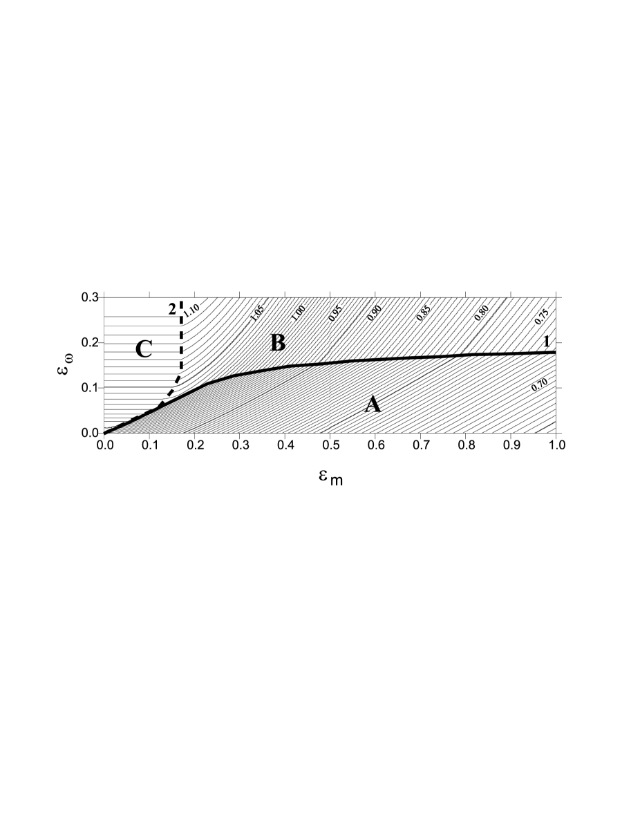
The curves of equal focusing time undergo a break on the two lines denoted by 1 and 2. Heavy solid line 1 corresponds to the critical case where the effects of electromagnetic and centrifugal forces on the dynamics of the fast MHD rarefaction wave are balanced near the focusing time. The front surface near the focusing time has a nearly spherical shape ( and tend to zero simultaneously as ). This critical curve separates two regions of parameters and . In region A below the critical curve, the magnetic field has a stronger effect on the rarefaction wave dynamics (and on the collapse as a whole). In this case, the rarefaction wave front surface has a prolate shape along the rotation axis and, hence, the focusing is transverse. In regions B and C above the critical curve, the rarefaction wave evolves with the dominant role of rotation. Near the focusing time, the rarefaction wave front surface has an oblate shape along the rotation axis. The relationship between the rotational, , and magnetic, , parameters on critical curve 1 can be roughly described by the empirical relation
| (24) |
The parameter depends on . For , .
In regions B and C, the rarefaction wave is focused in the longitudinal direction. In this case, the fast magnetosonic speed is . In region C (a weak magnetic field), the Alfvèn speed is lower than the isothermal speed of sound . Therefore, the focusing time in this region does not depend on the magnetic parameter and is the same as that for a rotating nonmagnetic cloud. The relationship between and on curve 2 that separates regions B and C can be found analytically using a perturbation analysis in the slow-rotation approximation (see Dudorov et al. 2004):
| (25) |
The focusing time also depends on the thermal parameter . We analyzed the behavior of the critical curves that separate regions A, B, and C as a function of the thermal parameter. As increases, curve 1 shifts upward, while curve 2 shifts rightward. Thus, the size of region A in which the rarefaction wave evolves with the dominant role of magnetic field increases with increasing . Accordingly, the size of the region in which the rarefaction wave evolves with the dominant role of rotation decreases. The relative size of region C, in which the focusing time does not depend on the magnetic parameter , also increases.
7 Comparison of analytical solutions with numerical simulations
The results of our analysis of the fast MHD rarefaction wave dynamics are in good agreement with our direct numerical simulations of the collapse of rotating magnetic protostellar clouds in the 2D approximation. The computations were performed on a grid in Euler variables in cylindrical coordinates using a numerical MHD code (Dudorov et al. 1999a) that is based on the total variation diminishing (TVD) scheme for MHD equations (Dudorov et al. 1999b).
Figures 5 and 6 present two cases of our numerical simulation of the collapse of rotating magnetic protostellar clouds. In both cases, the initial parameters of the clouds correspond to the thermal and magnetic parameters and , respectively. The rotational parameter is in the first case (Fig. 5) and in the second case (Fig. 6). The rotational parameter in the first case was chosen in such a way that the initial state of the cloud satisfied the conditions of region A (see Fig. 4), in which the dynamics of the fast MHD rarefaction wave is dominated by electromagnetic forces. In the second case of our simulation, the chosen initial model parameters satisfied the conditions of region B, in which the dynamics of the fast MHD rarefaction wave is dominated by centrifugal forces.
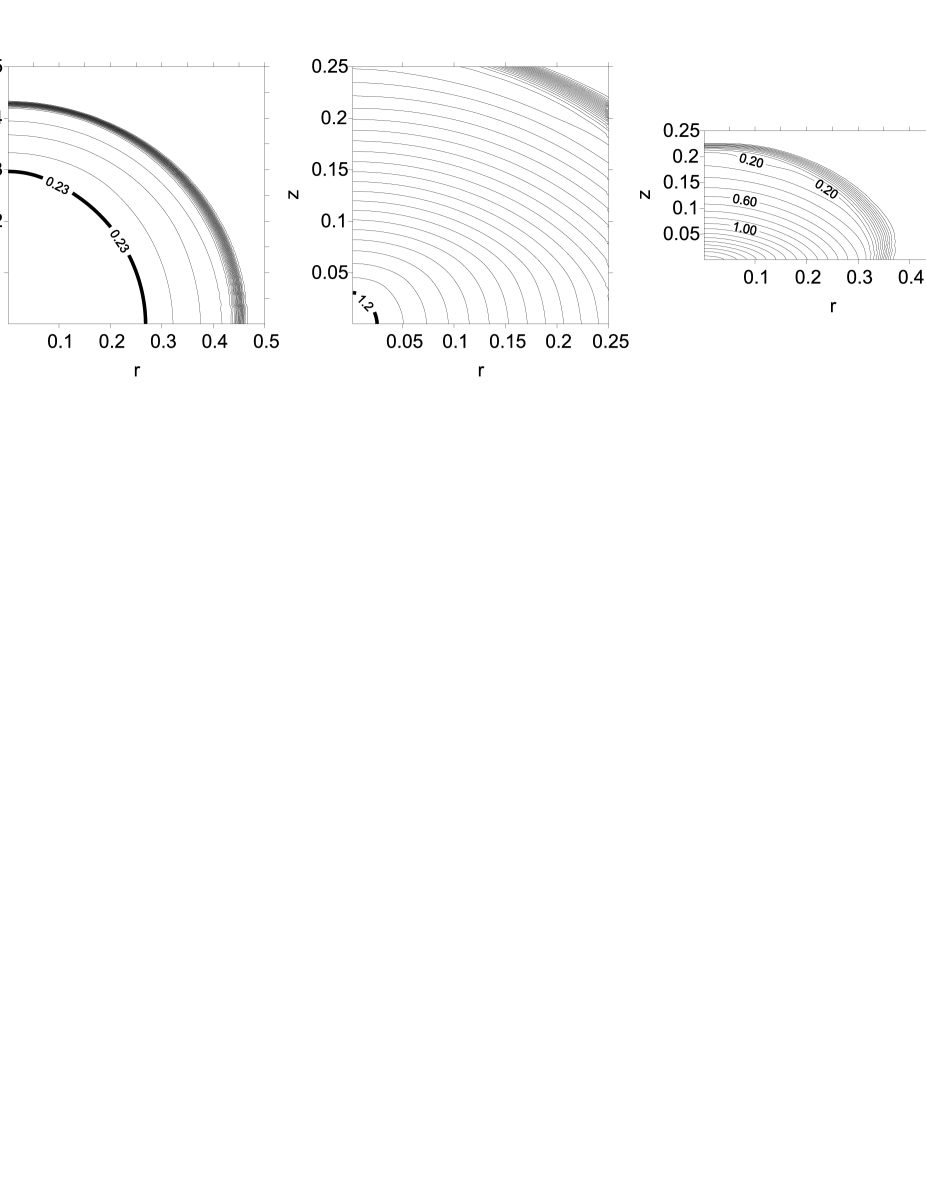
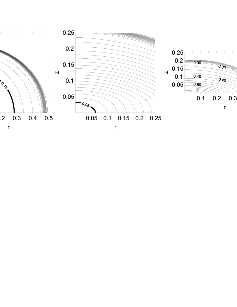
Figure 5 (the left and middle panels) shows the density distributions and positions of the fast MHD rarefaction wave front (heavy solid line) for the first case of our simulation for two times, and . The numbers on the isolines indicate the density logarithms. The rarefaction wave surface takes a prolate shape along the rotation axis similar to the shape of a prolate ellipsoid of revolution. In this case, the velocity of the collapsing gas slows down in the radial direction in the inhomogeneous region behind the rarefaction wave front due to the action of electromagnetic and centrifugal forces. Therefore, the cloud takes a flattened shape in the course of time. The middle panel corresponds to a time close to the focusing time. The shape of the rarefaction wave surface becomes highly prolate by this time. The right panel shows the density distribution in the cloud at time after the rarefaction wave focusing. The homogeneous region disappears by this time and the subsequent collapse proceeds against the background of a nonuniform density profile. In this case of our simulation, a cloud with a flattened disklike structure is formed in the final contraction stages.
The results of our numerical simulation in the second case are presented in Fig. 6. As in the first case, the left and middle panels show the density distribution and the positions of the fast MHD rarefaction wave front (heavy solid line) for times and . The rarefaction wave surface takes an oblate shape along the rotation axis similar to the shape of an oblate ellipsoid of revolution by the time . An oblate shape of the cloud is also formed behind the rarefaction wave front in the inhomogeneous region. In contrast to the previous case of our simulation, the rarefaction wave surface is identical in shape to the cloud configuration forming in the final contraction stage (see the right panel).
The focusing time of the fast MHD rarefaction wave determined by our numerical simulations is for the first case and for the second case. These values closely match the focusing times calculated analytically in this section (see Fig. 4).
8 Discussion and conclusions
In this paper, we have considered the formation of collapse nonuniformity for rotating magnetic protostellar clouds. Note that all of our results formulated for protostellar clouds are also valid for isothermal interstellar clouds. Within the framework of our statement of the problem of homogeneous cloud contraction in a pressure equilibrium with the external medium, the collapse dynamics is characterized by the generation of fast and slow MHD rarefaction waves at the cloud boundary and their subsequent propagation toward the cloud center. The surface of the fast MHD rarefaction front divides the entire volume of the collapsing cloud into two regions. In the inner region, the gas remains homogeneous and is characterized by uniform rotation and magnetic field. In this region, the pressure gradient is zero. In the outer region, nonuniform density, velocity, magnetic field, and angular velocity profiles are formed. The degree of nonuniformity can increase greatly with time. The slow MHD rarefaction wave propagates in the wake of the fast one against the background of an evolving nonuniformity, acting as a generator of perturbations in this region. Thus, the fast MHD rarefaction wave is mainly responsible for the collapse nonuniformity of rotating magnetic protostellar clouds. Its parameters (the front velocity and surface shape) determine the rate of evolution and degree of inhomogeneity of collapsing clouds.
Depending on the relationship between the parameters that characterize the initial magnetic field and rotation of the cloud, the shape of the fast MHD rarefaction wave surface can be both prolate and oblate along the rotation axis. Analyzing the rarefaction wave dynamics, we can identify two scenarios for the collapse of rotating magnetic protostellar clouds.
In the first case, the collapse takes place with the dominant role of a magnetic field. The surface of the fast MHD rarefaction wave has a prolate shape along the rotation axis and it is focused in the direction transverse to the magnetic field. In the second case, the collapse takes place with the dominant role of rotation. The surface of the fast MHD rarefaction wave has an oblate shape along the rotation axis and it is focused across the magnetic field. Here, we derived a criterion separating these two regimes of collapse (see (24)).
The cores of interstellar molecular clouds may be considered to be observational manifestations of protostellar clouds (Dudorov 1991). A direct observational confirmation of the gravitational collapse of some molecular cloud cores is the presence of characteristic signatures of contraction in molecular spectra (Tafalla et al. 1998; Williams et al. 1999; Gregersen and Evans 2000). The density distribution in the central parts of protostellar clouds is essentially uniform (Beuther et al. 2002; Caselli et al. 2002). For some clouds (L1536, L1512, L1498, L1544, L1495, TMC- 2, and others), there is observational evidence for the presence of weak discontinuities that separate the inner homogeneous region from the outer inhomogeneous region (Caselli et al. 2002). This may be considered as evidence for the existence of rarefaction waves propagating in these clouds. The shapes of the clouds themselves are also in satisfactory agreement with theoretical predictions. For example, an inner compact core of a nearly spherical or prolate (along the symmetry axis) shape and an extended oblate envelope are clearly identified in the clouds L1495, L1527, TMC-2, Per 5, Per 7, and L1582A. In other clouds (e.g., Per 6, L1400K, TMC-1, L260, and L1221), the central quasi-homogeneous core has a distinctly flattened shape along the symmetry axis. The clouds L1512 and L234A have double cores against the background of an oblate inhomogeneous envelope along the symmetry axis. This is probably because these clouds are gravitationally fragmented due to their rapid rotation. It should be noted that the observed density profiles in protostellar clouds given in the papers cited above were averaged over all directions. From the viewpoint of this paper, it would be interesting to compare the density profiles in the longitudinal and transverse directions with respect to the symmetry axis of these clouds, which is defined by the directions of the angular velocity and the largescale magnetic field.
In the outer inhomogeneous region (behind the fastMHDrarefaction wave front), differential rotation must lead to intense generation of a toroidal magnetic field. The toroidal magnetic field produces a braking torque that contributes to the redistribution of angular momentum between the central parts of the protostellar cloud and its periphery. Depending on the relationship between the parameters and , the magnetic braking of the cloud rotation can be effective or ineffective (Dudorov et al. 2004). Therefore, combining this criterion with the criterion associated with the rarefaction wave gives four fundamentally differentMHD collapse scenarios. A detailed analysis of these scenarios is the subject of a special paper. However, it is worth noting that in the case of ineffective magnetic braking, the angular momentum can be lost through other mechanisms (fragmentation, jet outflows, etc.). It should be emphasized once again that all these effects in protostellar clouds arise from the collapse nonuniformity produced by MHD rarefaction waves.
In all cases, the fast MHD rarefaction wave front surface in collapsing rotating magnetic protostellar clouds is nonspherical in shape. Therefore, its focusing and subsequent reflection from the center can be accompanied by the generation of (also nonspherical) intense nonlinear MHD waves that must affect the subsequent collapse dynamics. If the focusing time is close to the free-fall time (weak magnetic field, slow rotation, ), then the focusing will be accompanied by adiabatic gas heating in the central part of the cloud. The rise in gas temperature increases the rarefaction wave front velocity and the focusing can occur before an infinite density is reached at the cloud center (Zel’dovich and Kazhdan 1970). If the focusing time is shorter than the free-fall time (strong magnetic field, rapid rotation, ), then the focusing can occur even at the stage of isothermal contraction. Thus, in all cases, the rarefaction wave focusing acts as a physical factor that limits the density growth during collapse.
Thus, the fast MHD rarefaction wave that emerges in the early
contraction stages not only allows the collapse nonuniformity for
interstellar clouds to be explained, but also is a good tool for
studying this astrophysical phenomenon. It should be noted that the
conclusions reached here using semi-analytical methods are in good
agreement with the direct numerical simulations of the collapse of
rotating magnetic protostellar clouds that we have performed over
several years in the 1.5-D, 2-D, and 3-D approximations.
Acknowledgement. This work was supported by the Russian Foundation for Basic Research (project nos. 05-02-17070, 05-02-16123, and 04-02-96050 RFBR–Ural).
Appendix
Let us derive an expression for the velocity of a rarefaction wave front in a rotating magnetic cloud. The rarefaction wave front is the surface of a weak discontinuity on which all MHD quantities remain continuous, while their derivatives undergo a discontinuity. MHD equations (1)–(4) should be used in integral form to describe MHD flows with weak discontinuities (see Kulikovskii et al. 2001):
| (26) |
where is the vector of conservative variables, are the flux vectors in the , and directions in Cartesian coordinates, and is the source vector, which can include, for example, the gravitational force, the centrifugal force, the Coriolis force, and the like. We do not write out explicit expressions for these vectors to save space. The integration in (26) is over a certain stationary volume bounded by the surface and is an oriented element of this surface.
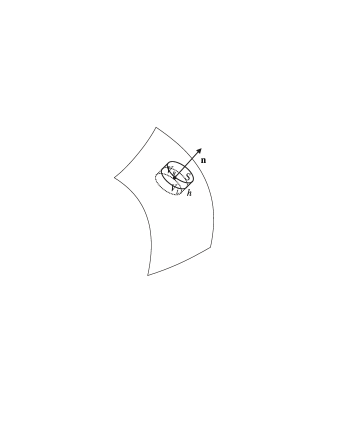
Consider a certain surface of a strong MHD discontinuity (see Fig. LABEL:fg07). Let us choose a small portion of this surface and construct a normal vector on it. As the volume , we choose a cylinder with height and base area . The discontinuity surface divides this cylinder into two regions, and (above and below the surface in the figure).
The limiting quantities to the left, , and to the right, , of the discontinuity surface near the selected small portion are related by the Hugoniot conditions. To derive these conditions, we will shrink the cylinder to the discontinuity surface () while leaving the base areas fixed. Simple calculations using (26) yield
| (27) |
where is the velocity of the discontinuity surface along the normal vector and the square brackets denote the difference between the limiting quantities . In the limit , the second and third terms on the left-hand side, the integral over the side surface of the cylinder, and the integral on the right-hand side of Eq. (27) tend to zero. As a result, we obtain the following Hugoniot conditions on the discontinuity surface:
| (28) |
where . Note, in particular, that the source terms do not appear in this relation.
To pass to the case of a weak discontinuity, we will assume that the right limiting values of differ from the left limiting values of by infinitesimals: . Expanding the right-hand side of Eq. (28) to linear terms in yields
| (29) |
where is the hyperbolicity matrix of the MHD equations. It follows from Eq. (29) that the velocity of a weak discontinuity coincides with one of the eigenvalues of the matrix , while coincides with one of its right eigenvectors. This determines the possible types of MHD weak discontinuities. For example, the fast MHD weak discontinuity (the fast MHD rarefaction wave front) considered in our paper corresponds to the eigenvalue , where is the normal (to the discontinuity surface) gas velocity and is the fast magnetosonic speed. Note that a similar result for the rarefaction wave front velocity can also be obtained more formally, by considering the conditions for the derivatives of vector u on the weak discontinuity surface.
References
-
1.
A.A. Barmin and V.V. Gogosov, Dokl. Akad. Nauk SSSR 134, 1041 (1960) [Sov. Phys. Dokl. 5, 961 (1960)].
-
2.
H. Beuther, P. Schlike, K.M. Menten, et al., Astrophys. J. 566, 945 (2002).
-
3.
P. Bodenheimer, Astrophys. J. 153, 483 (1968).
-
4.
P. Caselli, P.J. Benson, P.C. Myers, and M. Tafalla, Astrophys. J. 572, 238 (2002).
-
5.
M.J. Disney, Mon. Not. R. Astron. Soc. 175, 323 (1976).
-
6.
A.E. Dudorov, Astron. Zh. 68, 695 (1991) [Sov. Astron. 35, 342 (1991)].
-
7.
A.E. Dudorov, A.G. Zhilkin, and O.A. Kuznetsov, Mat. Model. 101, 109 (1999a).
-
8.
A.E. Dudorov, A.G. Zhilkin, and O.A. Kuznetsov, Mat. Model. 101, 101 (1999b).
-
9.
A.E. Dudorov and A.G. Zhilkin, Zh. Éksp. Teor. Fiz. 123, 195 (2003) [JETP 96, 165 (2003)].
-
10.
A.E. Dudorov, A.G. Zhilkin, N.Y. Zhilkina, MHD Rarefaction Wave as the Cause of Collapse Nonuniformity for Rotating Magnetic Protostellar Clouds. Proceedings of International Scientific Conference ”VII Zababakhin Scientific Talks”, Snezhinsk, 2004, pp. 1–16,
http://www.vniitf.ru/rig/konfer/7zst/reports/s3/s-3.html. -
11.
E.M. Gregersen and N.J. Evans, Astrophys. J. 538, 260 (2000).
-
12.
T. Hattory, T. Nakano, and C. Hayashi, Prog. Theor. Phys. 42, 4 (1969).
-
13.
A.G. Kulikovsky, N. V. Pogorelov, and A. Yu. Semenov, Mathematical Problems of the Numerical Solution of Hyperbolic Systems of Equations (Fizmatlit, Moscow, 2001) [in Russian].
-
14.
L.D. Landau and E.M. Lifshitz, Fluid Mechanics (Nauka, Moscow, 1988; Pergamon Press, Oxford, 1987).
-
15.
R.B. Larson, Mon. Not. R. Astron. Soc. 145, 271 (1969).
-
16.
R.B. Larson, Mon. Not. R. Astron. Soc. 156, 437 (1972).
-
17.
D. Lynden-Bell, Astrophys. J. 139, 1195 (1964).
-
18.
M.V. Penston, Mon. Not. R. Astron. Soc. 144, 425 (1969).
-
19.
L.I. Sedov, Similarity and Dimensional Methods in Mechanics (Nauka, Moscow, 1981; Academic, NewYork, 1959).
-
20.
F.H. Shu, Astrophys. J. 214, 488 (1977).
-
21.
M. Tafalla, D. Mardones, P.C. Myers, et al., Astrophys. J. 504, 900 (1998).
-
22.
K. Truelove, R. I. Klein,C. F.McKee, et al., Astrophys. J. 495, 821 (1998).
-
23.
T. Tsuribe and S. Inutsuka, Astrophys. J. 526, 307 (1999).
-
24.
J.P. Williams, P.C. Myers, D.J. Wilner, and J. Di Francesco, Astrophys. J. 513, L61 (1999).
-
25.
Ya. B. Zel’dovich and Ya. M. Kazhdan, Astrofizika 6, 109 (1970) [Astrophys. 6, 50 (1970)].
Translated by V. Astakhov