A mechanism for parallel electric field generation in the MHD limit: possible implications for the coronal heating problem in the two stage mechanism
Context. Using Particle-In-Cell simulations i.e. in the kinetic plasma description, the
discovery of a new mechanism of parallel electric field generation was recently
reported.
Aims. We show that the electric field generation parallel to the uniform unperturbed magnetic field
can be obtained in a much simpler framework using the ideal magnetohydrodynamics (MHD) description.
Methods. We solve numerically ideal, 2.5D, MHD equations in Cartesian coordinates,
with a plasma beta of 0.0001 starting from the equilibrium that mimics a
footpoint of a large curvature radius solar coronal loop or a polar
region plume. On top of such an equilibrium, a purely Alfvénic, linearly polarised, plane wave is launched.
Results. In ideal MHD the electric field parallel to the uniform unperturbed magnetic field
appears due to fast magnetosonic waves which are generated
by the interaction of weakly non-linear Alfvén waves with the transverse density inhomogeneity.
In the context of the coronal heating problem a new two stage mechanism of plasma heating is
presented by putting emphasis, first, on the generation of parallel electric fields within an ideal MHD description directly,
rather than focusing on the enhanced dissipation mechanisms of the Alfvén waves and, second, dissipation of these parallel electric
fields via kinetic effects.
It is shown that a single
Alfvén wave harmonic with frequency Hz and longitudinal wavelength Mm, for a putative
Alfvén speed of 4328 km s-1,
the generated parallel electric field could account for 10% of the necessary coronal heating requirement.
It is also shown that the amplitude of the generated parallel electric field
exceeds the Dreicer electric field by about four orders of magnitude, which implies realisation of the run-away regime
with associated electron acceleration.
Conclusions. We conjecture that wide spectrum (10 Hz) Alfvén waves, based on the
observationally constrained spectrum, could
provide the necessary coronal heating requirement.
The exact amount of energy that could be deposited by such waves through our mechanism of parallel electric field generation can
only be calculated once a more complete parametric study is done. Thus, the ”theoretical spectrum” of the energy stored in
parallel electric fields versus frequency needs to be obtained.
Key Words.:
Sun: oscillations – Sun: Corona – (Sun:) solar wind1 Introduction
The coronal heating problem, the puzzle of what maintains the solar corona 200 times hotter than the photosphere, is one of the main outstanding questions in solar physics (see e.g. Tsiklauri (2005) for a recent brief review on the subject). A significant amount of work has been done in the context of heating of open magnetic structures in the solar corona (Heyvaerts & Priest 1983; Nocera et al. 1986; Parker 1991; Nakariakov et al. 1997; DeMoortel et al. 2000; Botha et al. 2000; Tsiklauri et al. 2001; Hood et al. 2002; Tsiklauri & Nakariakov 2002; Tsiklauri et al. 2002, 2003). Historically, all phase mixing studies have been performed in the Magnetohydrodynamic (MHD) approximation; however, since the transverse scales in the Alfvén wave collapse progressively to zero, the MHD approximation is inevitably violated. Thus, Tsiklauri et al. (2005a, b) studied the phase mixing effect in the kinetic regime, using Particle-In-Cell simulations, i.e. beyond an MHD approximation, where a new mechanism for the acceleration of electrons due to the generation of a parallel electric field in the solar coronal context was discovered. This mechanism has important implications for various space and laboratory plasmas, e.g. the coronal heating problem and acceleration of the solar wind. It turns out that in the magnetosphere a similar parallel electric field generation mechanism in transversely inhomogeneous plasmas has been reported (Génot et al. 2004, 1999). See also Mottez et al. (2006) and references therein.
This new mechanism occurs when an Alfvén wave moves along the field in a plasma with a transverse density inhomogeneity. The progressive distortion of the Alfvén wave front due to differences of local Alfvén speed then generates the parallel electric field. In this work we show that the electric field generation parallel to the uniform unperturbed magnetic field can be obtained in a much simpler framework using an ideal MHD description, i.e. without resorting to complicated wave particle interaction effects such as ion polarisation drift and resulting space charge separation, which seems to be the fundamental cause of electron acceleration. See also the Discussion section for a more detailed account of what led us to consider the MHD approximation for parallel electric field generation.
In this paper, we also explore the implications of this effect for the coronal heating problem. Preliminary results have been reported elsewhere (Tsiklauri 2006). The present study explores the importance of MHD versus kinetic effects in solar plasmas, which has recently attracted considerable attention due to apparent difficulties in the coronal heating problem, as well as the natural tendency of wave heating models to proceed to progressively small spatial scales. Also, recent observations have indicated further sub-structuring of the coronal morphology (McEwan & DeMoortel 2006), which is relevant to our earlier work (Tsiklauri 2005).
2 The model, rationale and main results
Unlike previous studies (Tsiklauri et al. 2005a, b; Génot et al. 2004, 1999), here we use an ideal MHD description of the problem. We solve numerically ideal, 2.5D, MHD equations in Cartesian coordinates, with a plasma beta of 0.0001 starting from the following equilibrium configuration: A uniform magnetic field in the direction penetrates plasma with the density inhomogeneity across the direction, which varies according to
| (1) |
This means that the plasma density increases from some reference background value of , which in our case was fixed at g cm-3 (with a molecular weight of corresponding to the solar coronal conditions 1H:4He=10:1, Aschwanden (2004) and being the proton mass), to . Such a density profile across the magnetic field has steep gradients with a half-width of 3 Mm around Mm and is essentially flat elsewhere. Such a structure mimics e.g. the footpoint of a large curvature radius solar coronal loop or a polar region plume with the ratio of the density inhomogeneity scale and the loop/plume radius of 0.3, which is the median value of the observed range 0.15 - 0.5 (Goossens et al. 2002). The above quoted values of coordinate are in dimensionless units. We use the following usual normalisation , , . Here we fix to 100 G, and hence the dimensional Alfvén speed, turns out to be 4328 km s-1=0.0144 ( is the speed of light). The reference length was fixed to 1 Mm, i.e. the dimensionless time of unity corresponds to 0.2311 s. We usually omit the bar on the top of normalised quantities, hence when numbers are quoted without units, we refer to dimensionless units as defined above. The dimensionless Alfvén speed (normalised to ) is then . The simulation domain spans from Mm to 40 Mm in both and directions with the density ramp as described above mimicking a footpoint fragment of a solar coronal loop or a polar region plume. Our initial equilibrium is depicted in Fig. 1.

The initial conditions for the numerical simulation are and at , which means that a purely Alfvénic, linearly polarised, plane wave is launched travelling in the direction of positive s. The rest of the physical quantities, and (which would be components of fast magnetosonic waves if the medium were totally homogeneous) and and (the analogs of slow magnetosonic waves) are initially set to zero. The plasma temperature is varied as the inverse of Eq.(1) so that the total pressure always remains constant. Boundary conditions used in our simulations are periodic along the - and the zero gradient along the -coordinates. We fixed the amplitude of the Alfvén wave at 0.05 throughout. This choice makes the Alfvén wave weakly non-linear. Our motivation for this value was two-fold: First, this was the value used by Tsiklauri et al. (2005b); Génot et al. (2004), and as one of our goals here is to show that the parallel electric field generation is also possible in the MHD limit, we use this value. Tsiklauri et al. (2005b) only used one value of , while Génot et al. (2004) used several values of and showed that weak non-linearity (at ), in addition to the transverse density inhomogeneity, of course, is a key factor that facilitates parallel electric field generation. Smaller s reduced the effect of parallel electric field generation. Second, the observed values of the Alfvén waves at heights of Mm are about 50 km s-1, which for a typical Alfvén speed of 1000 km s-1 makes equal to 0.05. Such observations (see e.g. Moran (2001); Banerjee et al. (1998); Doyle et al. (1998)) indicate that off limb, heavy element (e.g. Si VIII) line broadening is beyond the thermal one, and hence mostly undamped, outward propagating Alfvén waves travel through the stratified plasma with increasing amplitude (due to the stratification).
All previous AC-type models of coronal heating focused on the mechanisms (e.g. phase mixing or resonant absorption) that could enhance damping of the Alfvén waves. However, for the coronal value of shear (Braginskii) viscosity, by which Alfvén waves damp of about m2 s-1, typical dissipation lengths (-fold decrease of Alfvén wave amplitude over those lengths) are Mm. Invoking the somewhat ad hoc concept of enhanced (anomalous) resistivity can reduce the dissipation length to the required value of the order of the hydrodynamic pressure scale height Mm. In this light (observation of mostly undamped Alfvén waves and the inability of classical (Braginskii) viscosity to produce a short enough dissipation length), it seems reasonable to focus rather on the generation of parallel electric fields which would guarantee plasma heating, should the energy density of the parallel electric fields be large enough. In both cases (AC-type MHD models and our model with parallel electric field generation) the energy comes from Alfvén waves. Therefore observing undamped Alfvén waves could mean two things: (i) the Alfvén waves observed through Doppler line broadening are low frequency ones, while high frequency Alfvén waves produce heating, hence they do not contribute to the observed line broadening. Clearly one cannot observe waves that have already dissipated; (ii) stratification (increase of Alfvén wave amplitude with height) could be balanced by the damping.
We emphasise parallel electric fields because in the direction parallel to the magnetic field electrons (and protons) are not constrained. In the direction perpendicular to the magnetic field, particles are constrained because of the large classical conductivity s-1 (for MK corona) and inhibited momentum transport across the magnetic field. The parameter that controls cross-field transport (flow) is , and not plasma which merely controls compressibility of the plasma. This is often confused in the literature.
In the ideal, linear MHD limit there are no parallel electric fields associated with the Alfvén wave. In the single fluid MHD the equation for the electric field can be obtained by differentiating Ohm’s law over time and then using Maxwell’s equations, expressing by (Krall & Trivelpiece 1973):
| (2) |
However, in the coronal plasma conductivity is so large that a more simple relation (obtained from Eq.(2)) can be used:
| (3) |
It is clear from the latter equation that the parallel electric field is
| (4) |
This means that in the considered system can only be generated if the initial Alfvén wave () is able to generate a fast magnetosonic wave (), which, in turn, is generated due to weak non-linearity and transverse density inhomogeneity.
Nakariakov et al. (1997) have investigated this possibility of growth of fast magnetosonic waves in a similar physical system, in a context other than parallel electric field generation. They used a mostly analytical approach and focused on the early stages of the system’s evolution. Later, the long-term evolution of the fast magnetosonic wave generation was studied numerically in the case of harmonic (Botha et al. 2000) and Gaussian (Tsiklauri et al. 2001) Alfvénic initial perturbations. When fast magnetoacoustic perturbations are initially absent and the initial amplitude of the plane Alfvén wave is small, the subsequent evolution of the wave, due to the difference in local Alfvén speed across the -coordinate, leads to the distortion of the wave front. This leads to the appearance of transverse (with respect to the applied magnetic field) gradients, which grow linearly with time. Nakariakov et al. (1997) have shown that with fairly good accuracy (which is substantiated by our numerical calculations presented below) the dynamics of the fast magnetoacoustic waves can be described by
| (5) |
Moreover, for small Alfvén wave amplitudes the back-reaction of the generated fast magnetosonic wave on the Alfvén wave can be neglected and Eq.(5) can be considered as a linear wave-like equation with a driver term on the right hand side where is given by the travelling wave expression . The main negative outcome of the studies with the harmonic (Botha et al. 2000) and Gaussian (Tsiklauri et al. 2001) Alfvénic initial perturbations was that despite the power-law growth in time of the driver term, which implies progressive growth of fast magnetosonic wave amplitude (at least until and reach the same amplitudes as and when the the back-reaction can no longer be neglected, rendering Eq.(5) invalid), the and amplitudes after rapid initial growth tend to saturate due to the destructive wave interference effect (Tsiklauri et al. 2001). As a self-consistency test, in the next sub-section we present results of the numerical simulation when the wavenumber of the initial Alfvén wave is . In dimensional units this corresponds to an Alfvén wave with frequency ( Hz), i.e. longitudinal wave-numbers Mm.
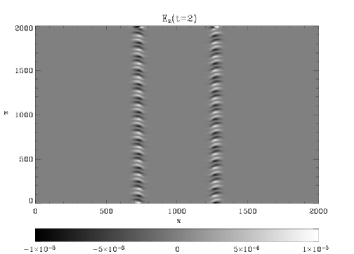
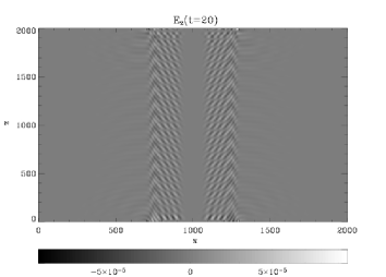
2.1 The case of an Alfvén wave with Hz
In Fig. 2 we show two snapshots of and (the latter was reconstructed using Eq.(4)) for the case of , i.e with Hz. The fast magnetosonic wave () and parallel electric field () are both generated in the vicinity of the density gradients , eventually filling the entire density ramp. This means that the generated parallel electric fields are confined by the density gradients, i.e. the solar coronal loop which the considered system tries to mimic after about 20 Alfvén time scales becomes filled with temporally oscillating parallel electric fields. Note that this can be a source of polarisation drift of ions if kinetic effects are considered.
In Fig. (3) we plot the amplitudes of and which we define as the maxima of absolute values of the wave amplitudes along the line (which track the generated wave amplitudes in the strongest density gradient regions) at a given time step. Solid lines represent solutions using the linear McCormack code, which solves Eq.(5) with the initial conditions as described above, while dash-dotted lines with open symbols are the solutions using the non-linear MHD code Lare2d (Arber et al. 2001). We refer to the McCormack code as linear because we treat Eq.(5) as a linear wave-like equation with a driver term on the right hand side where is given by the travelling wave form . Here for both runs we use a spatial grid resolution. Note that data with solid lines is plotted with much smaller time steps than those with dash-dotted lines and open symbols, which are plotted with the much coarser time step of . This is due to the fact that Lare2d uses MPI parallelisation and hence tracking time evolution of the solution at a given point of the simulation domain (which is split into many parts) is a difficult task. The linear McCormack code is serial, hence we do not encounter such problems. The two main observations are:


(i) We gather from Fig. (3) that as in the previous cases (Botha et al. 2000; Tsiklauri et al. 2001) the amplitude of initially grows rapidly and then tends to saturate at a level of , as one might expect from the weakly non-linear theory (cf. Eq.(5)).
(ii) The solutions produced by the fully non-linear MHD code and the linear McCormack code are similar but not identical. This can be explained by the fact that the amplitude of is now large enough for the non-linearity effects to be noticeable. Note that when the amplitude was much smaller, , the deviations between the two were much smaller (cf. Fig.(6) from Tsiklauri et al. (2001)). In the case of with Lare2d, weak non-linearity of the phase-mixed Alfvén wave even causes noticeable deviations in the initial background density, which is an effect previously discussed in the literature.
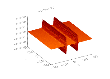
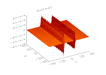
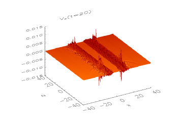
2.2 The case of an Alfvén wave with Hz
Here we present results for the case of large wave-numbers, , which in dimensional units corresponds to an Alfvén wave with Hz, and Mm. This is a regime not investigated before. Fig. (4) is similar to Fig.(2) but now , with shaded surface plots given instead of intensity plots. This is due to the fact that spiky data do not appear clearly using intensity plots. We gather from this graph that similarly to the results of Tsiklauri et al. (2005b) and Génot et al. (2004), the generated parallel electric field is quite spiky, but more importantly, large wavenumbers i.e. short wavelengths now are able to significantly increase the amplitudes of both the fast magnetosonic waves () and the parallel electric field . This amplitude growth is beyond a simple scaling (discussed in the previous sub-section). The amplitude growth is presented quantitatively in Fig. (5). The amplitude of now attains values of 0.01, unlike for moderate s. This boost in amplitude growth can be explained qualitatively by analysing Eq.(5). The driver term (right hand side of Eq.(5)) contains spatial derivatives. Thus, large wavenumbers (i.e. stronger spatial gradients) seem to boost the values of the driver term which in turn yields larger values for the level of saturation of the amplitude. In the considered case, now attains values of 0.001.
Since the amplitude of attains a sizable fraction of the Alfvén wave amplitude rendering weakly non-linear theory inapplicable, we do not plot solutions obtained from the the linear McCormack code. Instead, to verify the convergence of the solution, we plot the results of the numerical run with doubled () spatial resolution. The match seems satisfactory, which validates the obtained results.


2.3 Application of the results to the coronal heating problem
It has been known for decades (Kuperus et al. 1981) that the coronal energy losses that need to be compensated by some additional energy input, to keep the solar corona at the observed temperatures, are (in units of erg cm-2 s-1): for the quiet Sun, for a coronal hole and for an active region. Aschwanden (2004) makes similar estimates for the heating flux per unit area (i.e. in erg cm-2 s-1):
| (6) |
where erg cm-3 s-1. This yields an estimate of erg cm-2 s-1 in an active region with a typical loop base electron number density of cm-3 and MK.
The energy density associated with the parallel electric field is
| (7) |
where is the dielectric permitivity of plasma. The latter can be conveniently deduced from the expression for the polarisation current (Krall & Trivelpiece (1973), appendix I)
| (8) |
and Maxwell’s equation written as
| (9) |
The result is
| (10) |
The latter formula is different from the usual expression for the dielectric permitivity (Krall & Trivelpiece 1973):
| (11) |
because the displacement current has been neglected in the above treatment, which is a usual assumption made in the MHD limit. For the coronal conditions ( g cm-3, , Gauss) the second term in Eq.(11) is which means that for the coronal conditions in the energy density Eq.(7) the dominant term is
| (12) |
which is the kinetic energy density associated with the drift (Sturrock (1994), page 60). In Fig. (5) we saw that electric field amplitude attains a value of . In order to convert this to dimensional units we use km s-1 and G and Eqs.(3-4) to obtain statvolt cm-1 (in Gaussian units). Therefore the energy density associated with the parallel electric field (From Eq.(7)) is
| (13) |
In order to get the heating flux per unit area for a single harmonic with frequency 7 Hz, we multiply the latter expression by the Alfvén speed of 4328 km s-1 (because the fast magnetosonic waves ( and ) that propagate across the magnetic field and associated parallel electric fields () are generated in density gradients by the Alfvén waves. Hence, the flux is carried with the Alfvén speed) to obtain
| (14) |
which is % of the coronal heating requirement estimate for the same parameters made above using Eq.(6). Note that the latter estimate is for a single harmonic with frequency 7 Hz (see the Discussion section for details when a wide spectrum of Alfvén waves is considered).
3 Dissipation of the generated parallel electric fields
We now discuss how the energy stored in the generated parallel electric field is dissipated. We examine the parallel electric field behaviour at a given point in space as a function of time. In Fig. (6) we plot the time evolution of at a point for the case of , Hz, and Mm. Choice of this -value is such that it captures parallel electric field dynamics at the strongest density gradient point (across ).

We gather from Fig. (6) that is a periodic (sign-changing) function that is a mixture of two harmonics with frequencies and . This is due to the fact that is calculated using Eq.(4) where and at fixed spatial points vary in time with frequencies , while the generated and vary with frequencies (Nakariakov et al. 1997). Because of the ideal MHD approximation used in this paper, the generated electric field cannot accelerate plasma particles or cause Ohmic heating unless kinetic effects are invoked. Let us look at Ohm’s law for ideal MHD (Eq.(3)) in more detail denoting physical quantities unperturbed by the waves with subscript 0 and ones associated with the waves by a prime; initial equilibrium implies with . For the perturbed state (with Alfvén waves ( and ) launched which generate fast magnetosonic waves ( and ) ) we have
| (15) |
Note that the projection of on the full magnetic field (unperturbed plus the waves ) is zero by the definition of the cross and scalar product: . Physically this means that in ideal MHD the electric field cannot do any work as it is always perpendicular to the full (background plus wave) magnetic field. However the projection of on the unperturbed magnetic field is clearly non-zero
| (16) |
which exactly coincides with Eq.(4) that was used to calculate . The crucial next step that is needed to understand how the generated electric fields parallel to the uniform unperturbed magnetic field dissipate must invoke kinetic effects. In our two stage model, in the first stage, bulk MHD motion (waves) generate parallel electric fields, which as we saw cannot accelerate particles if we describe the plasma in the ideal MHD limit. Génot et al. (2004) and Tsiklauri et al. (2005b) showed that when the identical system is modelled in the kinetic regime particles are accelerated with such parallel fields. Génot et al. (2004) claimed that electron acceleration is due to the polarisation drift. They showed that once the Alfvén wave propagates along the density gradient that is transverse to the magnetic field, a parallel electric field is generated due to charge separation caused by the polarisation drift associated with the time-varying electric field of the Alfvén wave. Because the polarisation drift speed is proportional to the mass of the particle, it is negligible for electrons, hence ions start to drift. This causes charge separation (the effect that cannot be treated by a MHD description), which results in generation of parallel electric fields, that in turn accelerate electrons. As was shown in Fig.(6), our parallel electric field is also time-varying, hence at the second (kinetic) stage the electron acceleration can proceed in the same manner through ion polarisation drift and charge separation. The exact picture of the particle dynamics in this case can no longer be treated with MHD and a kinetic description is more relevant. The frequencies considered in the kinetic regime (Tsiklauri et al. 2005b), Hz and Hz (this paper) are different, but we clearly saw that the increase in frequency results in enhancement of the parallel electric field generation. Various effects of wave-particle interactions will rapidly dampen the parallel electric fields on a time scale much shorter than the MHD time scale. Génot et al. (2004) clearly demonstrated the role of nonlinearity and kinetic instabilities in the rapid conversion from the initial low frequency electromagnetic regime to a high frequency electrostatic one. They identified Buneman and weak beam plasma instabilities in their simulations (as they studied the time evolution of the system for longer than Tsiklauri et al. (2005b)). Fig.(11) from Génot et al. (2004) shows that wave energy is converted into particle energy on times scales of Alfvén periods. Perhaps no immediate comparison is possible (because of the different frequencies involved), but still in our case the Alfvén period when sufficient energy is stored in the parallel electric field is Hz)=0.14 s, i.e. wave energy is converted into particle energy in a short time.
Yet another important observation can be made by estimating the Dreicer electric field (Dreicer 1959). Dreicer considered dynamics of electrons under the action of two effects: the parallel electric field and friction between electrons and ions. He noted that the equation describing electron dynamics along the magnetic field can be written as
| (17) |
where is the electron drift velocity and is the electron collision frequency and dot denotes time derivative. When Eq.(17) in the steady state regime, () allows us to derive the expression for Spitzer resistivity. When , the steady state solution may not apply. In this case, when the right hand side of Eq.(17) is positive i.e. when , we have electron acceleration. This is the so-called run-away regime. In simple terms, acceleration due to the parallel electric field leads to an increase in ; in turn, this leads to a decrease in because . Thus, when the electric field exceeds the critical value (the Dreicer electric field, which is quoted here in its SI form), faster drift leads to a decrease in electron-ion friction, which in turn results in even faster drift and hence the run-away regime is reached. Putting coronal values ( cm-3, MK and ) in the expression for the Dreicer electric field we obtain 0.0054 V m-1 which in Gaussian units is statvolt cm-1. As can be seen from this estimate, the amplitudes of the parallel electric field obtained in this paper exceeds the Dreicer electric field by about four orders of magnitude. This guarantees that the run-away regime would take place leading to electron acceleration and fast conversion of the generated electric field energy into heat. In Eq.(17) is constant, while our at the point of strongest density gradient is time varying. Hence some modification of the Dreicer analysis is expected.
4 Discussion
After the comment paper by Mottez et al. (2006) we came to the realisation that the electron acceleration seen in both series of works (Tsiklauri et al. 2005a, b; Génot et al. 2004, 1999) is a non-resonant wave-particle interaction effect. In works by Tsiklauri et al. (2005a, b) the electron thermal speed was while the Alfvén speed in the strongest density gradient regions was ; this unfortunate coincidence led us to the conclusion that the electron acceleration by parallel electric fields was affected by the Landau resonance with the phase-mixed Alfvén wave. In works by Génot et al. (2004, 1999) the electron thermal speed was while the Alfvén speed was because they considered a more strongly magnetised plasma applicable to Earth magnetospheric conditions. However, the interaction of the Alfvén wave with a transverse density plasma inhomogeneity when the Landau resonance condition is met can be quite important for the electron acceleration (Chaston et al. 2000; Hasegawa & Chen 1976). Chaston et al. (2000) assert that the electron acceleration observed in density cavities in aurorae can be explained by the Landau resonance of the cold ionospheric electrons with the Alfvén wave. Hasegawa & Chen (1976) also established that at resonance the Alfvén wave fully converts into the kinetic Alfvén wave with a perpendicular wavelength comparable to the ion gyro-radius. We can then conjecture that because of kinetic Alfvén wave front stretching (due to phase mixing, i.e. due to the differences in local Alfvén speed), this perpendicular component gradually realigns with the ambient magnetic field and hence creates the time varying parallel electric field component. This points to the importance of the Landau resonance for electron acceleration when the resonance condition is met. But as seen in works of Génot et al. (2004, 1999), even when the resonance condition is not met, electron acceleration is still possible.
There were three main stages that lead to the formulation of the present model:
(i) The realisation that the parallel electric field generation (and particle acceleration) is a non-resonant wave-particle interaction effect lead us to the question: could such parallel electric fields be generated in a MHD approximation?
(ii) If one considers non-linear generation of the fast magnetosonic waves in the transversely inhomogeneous plasma, then contains a non-zero component parallel to the ambient magnetic field .
(iii) From previous studies (Botha et al. 2000; Tsiklauri et al. 2001) we knew that the fast magnetosonic waves ( and ) did not grow to a substantial fraction of the Alfvén wave amplitude. However, after reproducing the old parameter regime (k=1, i.e a frequency of 0.7 Hz), the case of k=10, i.e a frequency of 7 Hz was considered, which showed that fast magnetosonic waves and in turn a parallel electric field were more efficiently generated.
There are two main issues that need to be discussed to address the plausibility of the proposed model: (i) the plausibility of parameters used in the model and (ii) the relation to the observations.
First, the parameter space of the problem is quite large. The level at which the fast magnetosonic wave ( and ) and hence the parallel electric field () amplitudes saturate depends on several parameters. As indicated previously (Botha et al. 2000; Tsiklauri et al. 2001), this level depends on the strength of the transverse density gradient and the wavelength (width in the case of a Gaussian Alfvénic pulse) of the Alfvén wave. In particular it was found that the stronger density gradients yield lower saturation levels of the fast magnetosonic wave amplitude (due to the fact that destructive wave interference starts earlier when the density gradients are strong), while shorter wavelengths (width in the case of the Gaussian Alfvénic pulse) of the Alfvén wave generate higher levels (e.g. Figs. 11 and 12 in Tsiklauri et al. (2001)). We have not done a full parameter space investigation to demonstrate the effect, but instead we fixed the transverse density gradient guided by observations. In particular, the observed length scale of the density inhomogeneities in loops vary between 0.15 and 0.5 loop radii (Goossens et al. 2002). In our model the length scale of the density inhomogeneity (half-width) is 3 Mm and the loop radius is 10 Mm (see Fig. 1) which makes the ratio 0.3. This is the median value in the observed range (0.15 – 0.5). This eliminates one parameter of variability in the parameter space. For the Alfvén speed, we used a putative value of 4328 km s-1 and performed two numerical runs for two frequencies, 0.7 and 7 Hz. A full investigation should map a range of frequencies. Such an analysis is pending, but see below for preliminary estimates in the context of coronal heating.

Second, Alfvén waves as observed in situ in the solar wind always appear to be propagating away from the Sun and it is therefore natural to assume a solar origin for these fluctuations. However, the precise origin in the solar atmosphere of the hypothetical source spectrum for Alfvén waves (turbulence) is unknown, given the impossibility of remote magnetic field observations above the chromosphere-corona transition region (Velli & Pruneti 1997). Studies of ion cyclotron resonance heating of the solar corona and high speed winds exist which provide important spectroscopic constraints on the Alfvén wave spectrum (Cranmer et al. 1999). Although the spectrum can and is observed at distances of 0.3 AU, it can be projected back to the base of corona using empirical constraints, see e.g. the top line in Fig. 5 from Cranmer et al. (1999) (see also the more elaborate model of Cranmer & van Ballegoouen (2005)). Using the latter figure we can make the following estimates. Let us look at single harmonic, first. At a frequency of 7 Hz (used in our simulations), the magnetic energy of Alfvénic fluctuations is nT2 Hz-1. For a single harmonic with Hz this gives for the energy density G erg cm-3. Surprisingly this semi-observational value is quite close to the theoretical value given by Eq.(13). As we saw above, such a single harmonic can provide approximately 10 % of the coronal heating requirement. Next let us look at how much energy density is stored in the Alfvén wave spectrum based on the empirically guided top line in Fig. 5 from Cranmer et al. (1999). Their spectral energy density (which they call ”power”) is approximated by the so-called spectrum, i.e. nT2 Hz-1. In proper energy density units this is erg cm-3 Hz -1. Thus, the flux carried by Alfvén waves from say Hz up to a frequency would be
| (18) |
. It is instructive to look at this equation graphically in Fig.(7): the Alfvén wave spectrum from Hz up to about a few Hz carries a flux that is nearly as much as the coronal heating requirement (Eq.(6)) with MK. We do not consider higher frequencies because at about Hz, ions become resonant with circularly polarised Alfvén waves and dissipation proceeds though Landau resonance – a well-studied mechanism, but quite different from our non-resonant mechanism of parallel electric field generation.
There are several possibilities of how this flux carried by Alfvén waves (fluctuations) is dissipated. If we consider the regime of frequencies up to Hz, the ion cyclotron resonance condition is not met and hence dissipation is dominated by the mechanism of parallel electric field dissipation formulated in this paper. However, at this stage it is unclear how much energy could actually be dissipated. This is due to the fact that we only have two points, 0.7 Hz and 7 Hz, in our ”theoretical spectrum”. As we saw, a single Alfvén wave harmonic with frequency 7 Hz can dissipate enough heat to account for 10% of the coronal heating requirement. Eq.(18) shows how much flux is carried by the Alfvén waves, while in order to calculate how much of it is actually dissipated depends on what level from Eq.(14) will attain for each harmonic. Hence, the flux dissipation through our mechanism would be
| (19) |
where is the ”theoretical spectrum” of the energy stored in parallel electric fields. For a 7 Hz single harmonic it can be obtained from
| (20) |
with from Eq.(13) rendering . For a 0.7 Hz single harmonic would be different because as can be seen from Fig.(3) (as opposed to for Hz). Since scales as , then . More numerical runs are needed to fully map . This is deferred until further work is done.
A clear distinction should be made between our model and the ones that use ion cyclotron resonance damping of Alfvén waves. Low frequency (0.001-0.1 Hz) Alfvén waves dominate the power spectrum of fluctuations in the solar wind at and beyond 0.3 AU. These waves are able to transport a significant amount of energy (Cranmer et al. 1999). On the contrary, high frequency (10-10000 Hz) Alfvén waves are known to damp more easily than their low frequency counterparts, but they are not expected to contain much power. This is problematic for ion cyclotron resonance damping models because Landau resonance of ions occurs at high frequencies (few Hz). Our model on the contrary is of a non-resonant nature. Thus, it is hoped that it can provide enough heating once the frequency range 10 Hz at the base of corona is mapped numerically (i.e. once the level attained by the parallel electric field amplitudes for each frequency is determined). The proposed wide spectrum idea for Alfvén waves is not as ”theoretical-rather-than-demonstrable” as the one proposed by Tsiklauri & Nakariakov (2001) for the slow magnetosonic waves. One could question the validity of the wide spectrum idea for the slow magnetosonic waves in coronal loops as predominantly single harmonics (with periods of 3 and 5 minutes, etc.) are observed. At the same time it is not possible to observe the high frequency waves that are dissipated already. However, in the case of Alfvén waves, the presence of a wide spectrum with a frequency range of 10 Hz at the base of corona, which is actually observed at 0.3 AU, seems to be more likely. The possibility of meeting the full coronal heating requirement with the wide spectrum Alfvén waves via the proposed two stage mechanism of parallel electric field generation needs further investigation.
Acknowledgements.
The author acknowledges support from the Nuffield Foundation (UK) through an award to newly appointed lecturers in Science, Engineering and Mathematics (NUF-NAL 04), from the University of Salford Research Investment Fund 2005 grant, PPARC (UK) standard grant and use of the E. Copson Math cluster funded by PPARC and the University of St. Andrews. The author would like to thank E.R. Priest and K.G. McClements for useful discussions and criticism and the anonymous referee for useful comments and suggestions.References
- Arber et al. (2001) Arber T.D., Longbottom A.W., Gerrard C.L., et al., 2001, J. Comput. Phys., 171, 151
- Aschwanden (2004) Aschwanden M.J., 2004, Physics of the solar corona an introduction, Praxis Publishing Ltd, Chichester, UK
- Banerjee et al. (1998) Banerjee D., Teriaca L., Doyle J., et al., 1998, Astron. Astrophys., 339, 208
- Botha et al. (2000) Botha G.J.J., Arber T.D., Nakariakov V.M., et al., 2000, Astron. Astrophys., 363, 1186
- Chaston et al. (2000) Chaston C.C., Carlson C.W., Ergun R.E., et al., 2000, Phys. Scripta, T84, 64
- Cranmer & van Ballegoouen (2005) Cranmer S.R., van Ballegoouen A.A., 2005, Astrophys. J. Suppl. Ser., 156, 265
- Cranmer et al. (1999) Cranmer S.R., Field G.B., Kohl J.L., 1999, Astrophys. J., 518, 937
- DeMoortel et al. (2000) DeMoortel I., Hood A.W., Arber T.D., 2000, Astron. Astrophys., 354, 334
- Doyle et al. (1998) Doyle J., Banerjee D., Perez M., 1998, Sol. Phys., 181, 91
- Dreicer (1959) Dreicer H., 1959, Phys. Rev., 115, 238
- Génot et al. (1999) Génot V., Louarn P., Quéau D.L., 1999, J. Geophys. Res., 104, 22649
- Génot et al. (2004) Génot V., Louarn P., Mottez F., 2004, Ann. Geophys., 6, 2081
- Goossens et al. (2002) Goossens M., Andries J., Aschwanden M.J., 2002, Astron. Astrophys., 394, L39
- Hasegawa & Chen (1976) Hasegawa A., Chen L., 1976, Phys. Fluids, 19, 1924
- Heyvaerts & Priest (1983) Heyvaerts J., Priest E.R., 1983, Astron. Astrophys., 117, 220
- Hood et al. (2002) Hood A.W., Brooks S.J., Wright A.N., 2002, Proc. Roy. Soc. Lond. A, 458, 2307
- Krall & Trivelpiece (1973) Krall N.A., Trivelpiece A.W., 1973, Principles of Plasma Physics, McGraw-Hill, New York
- Kuperus et al. (1981) Kuperus M., Ionson J.A., Spicer D.S., 1981, Ann. Rev. Astron. Astrophys., 19, 7
- McEwan & DeMoortel (2006) McEwan M.P., DeMoortel I., 2006, Astron. Astrophys., 448, 763
- Moran (2001) Moran T.G., 2001, Astron. Astrophys., 374, L9
- Mottez et al. (2006) Mottez F., Génot V., Louarn P., 2006, Astron. Astrophys., 449, 449
- Nakariakov et al. (1997) Nakariakov V.M., Roberts B., Murawski K., 1997, Sol. Phys., 175, 93
- Nocera et al. (1986) Nocera L., Priest E.R., Hollweg J.V., 1986, Geophys. Astrophys. Fl. Dyn., 35, 111
- Parker (1991) Parker E.N., 1991, Astrophys. J., 376, 355
- Sturrock (1994) Sturrock P.A., 1994, Plasma Physics: an introduction to the theory of astrophysical, geophysical and laboratory plasmas, Cambridge University Press, Cambridge, UK
- Tsiklauri (2005) Tsiklauri D., 2005, Astron. Astrophys., 441, 1177
- Tsiklauri (2006) Tsiklauri D., 2006, New J. Phys. 8, 79
- Tsiklauri & Nakariakov (2001) Tsiklauri D., Nakariakov V.M., 2001, Astron. Astrophys., 379, 1106
- Tsiklauri & Nakariakov (2002) Tsiklauri D., Nakariakov V.M., 2002, Astron. Astrophys., 393, 321
- Tsiklauri et al. (2001) Tsiklauri D., Arber T.D., Nakariakov V.M., 2001, Astron. Astrophys., 379, 1098
- Tsiklauri et al. (2002) Tsiklauri D., Nakariakov V.M., Arber T.D., 2002, Astron. Astrophys., 395, 285
- Tsiklauri et al. (2003) Tsiklauri D., Nakariakov V.M., Rowlands G., 2003, Astron. Astrophys., 400, 1051
- Tsiklauri et al. (2005a) Tsiklauri D., Sakai J.I., Saito S., 2005a, New J. Phys., 7, 79
- Tsiklauri et al. (2005b) Tsiklauri D., Sakai J.I., Saito S., 2005b, Astron. Astrophys., 435, 1105
- Velli & Pruneti (1997) Velli M., Pruneti F., 1997, Plasma Phys. Control. Fusion, 39, B317