The University of Hawaii Wide Field Imager (UHWFI)
Abstract
The University of Hawaii Wide-Field Imager (UHWFI) is a focal compressor system designed to project the full half-degree field of the UH 2.2 m telescope onto the refurbished UH 8K8K CCD camera. The optics use Ohara glasses and are mounted in an oil-filled cell to minimize light losses and ghost images from the large number of internal lens surfaces. The UHWFI is equipped with a six-position filter wheel and a rotating sector blade shutter, both driven by stepper motors. The instrument saw first light in 2004 in an engineering mode. After filling the lens cell with index matching oil, integration of all software components into the user interface, tuning of the CCD performance, and the purchase of the final filter set, UHWFI now fully commissioned at the UH 2.2 m telescope.
1 Introduction
The University of Hawaii (UH) 2.2 m telescope on Mauna Kea is a Ritchey-Chretien optical system originally designed in the 1960s to image large fields in seeing-limited quality onto photographic plates. While wide-field imaging is one of the main functions provided by small and mid-sized telescopes in today’s era of large (8-m class) telescope facilities, the wide field capability of the UH telescope has not been fully utilized since photographic work was effectively abandoned some 20 years ago.
The desire to use the UH 2.2 m telescope in a flexible schedule for a variety of search and monitoring programs lead to the building of the UH 8K8K CCD camera, which was the first large mosaic CCD camera in the world (Luppino, Mezger, & Miyazaki, 1995). This original version of the UH 8K camera provided an 1818 field at the f/10 Ritchey-Chretien focus of the UH 2.2 m telescope using a field flattener lens as the dewar window. The UH 8K camera was also used at the CFHT 3.6m telescope prime focus but has since been replaced there first by the CFHT 12K camera (Starr et al., 2000) and more recently by Megacam (Boulade et al., 2003).
The UH 8K camera was recently upgraded with science-grade deep depletion CCDs. These new, backside illuminated and anti-reflection coated deep depletion CCID-20 devices give the UH 8K camera a substantially increased sensitivity per pixel, in particular in the far optical (0.8 - 1.1 m) part of the spectrum.
As an additional step toward improving the capabilities of the UH 2.2 m telescope and toward regaining the full wide field capability of this telescope we have built a new focal compression optical system, filter wheel and shutter. In conjunction with this new University of Hawaii Wide Field Imager (UHWFI), the refurbished UH 8K camera covers essentially the full field that the UH 2.2 m telescope provides. This paper describes the main design features of this new system.
2 Basic Design Choices
We initially explored various ways to increase the field coverage of the 8K CCD camera for search and monitoring programs. Building an entirely new prime focus system for the UH 2.2 m telescope was considered as a way of obtaining fields in excess of 30 but was rejected since it was prohibitively expensive and would preclude the rapid change between instruments. A simpler and more cost effective solution is to build a focal compressor and field corrector that allows the full unvignetted field of 30 of the telescope field to be observed at a seeing-limited pixel scale.
The design of a wide field corrector for the UH 2.2 m telescope was constrained by many design features of the telescope, operational considerations, and budget limitations. The UH 2.2 m telescope has two bent Cassegrain ports and the standard direct Cassegrain focus position. Operationally, using the UHWFI at one of the bent Cassegrain foci and leaving it installed there permanently would have been advantageous. However, the bent Cassegrain focus has a more limited field of view than the direct Cassegrain focus. The direct focus position was therefore chosen for UHWFI.
At the Cassegrain focus, the existing autoguider limits the field of view. We decided therefore to use UHWFI without the autoguider. For short exposure times, we can rely on the open-loop tracking of the telescope, which has been substantially improved with the new control sytem (Lovell et al., 2000) of the UH 2.2 m telescope. We have mechanically prepared the UH 8K camera focal plane assembly for the future installation of small guide CCD chips at the edges of the 8K8K CCD mosaic in a planned upgrade of this CCD camera.
3 Optics Design
The focal compressor optics are designed to shorten the focal length of the UH 2.2 m telescope from the original 22.9 m to a focal length of f=13.5 m. The focal plane scale therefore is 65.4 m/arcsec, resulting in a pixel scale of 0.229 arcsec pixel-1 for the 15 m CCD pixels of the UH 8K, and approximately a field of view, taking into account some dead space between the individual CCDs in the 8K8K mosaic focal plane. The extreme corners of the field are slightly (10%) vignetted by the secondary mirror, but the vignetting is well within what is easily correctable by proper flat-fielding of the data. Grid distortion by the focal compressor is a maximum of 2.8% in the corners of the field and can be corrected in software, for example using the IRAF ”geomap” and ”geotran” tasks.
The optical design was optimized using an as-built model of the UH 2.2 m telescope optics. The slight spherical aberration caused by the mismatch of the primary and secondary mirror conic constants was included in the optimization process of the lenses and could therefore be partly corrected.
The design of the optics for UHWFI was an iterative process, adjusting the design several times to the availability and price of optical glasses. As a result of this process, the design represents a relatively low-cost solution. All designs considered in this process consisted of a first lens group with positive optical power, doing the actual focal compression, and a field-flattening lens of negative optical power close to the focal plane. The latter also served as the CCD camera dewar window. The size of the first and largest lens is limited by the diameter of the Cassegrain port in the telescope’s primary mirror cell. For cost reasons, we were forced to abandon very good triplet designs for the first lens group that used two large CaF2 lenses in combination with a single optical glass lens of negative power. With a lens diameter of 32 cm and a thickness of 7.5 cm for the largest CaF2 lens, the cost of the CaF2 material was prohibitive for our project.
Our design now substitutes Ohara S-FPL51Y glass for CaF2. This glass is the lowest dispersion glass in Ohara’s product line that could be fabricated in the diameter required for UHWFI. Since S-FPL51Y cannot be fabricated in thick plates due to crystallization problems during the cooldown, the two thick lenses of the original CaF2 design both are split up into two thinner ones that are within the fabrication limit of the raw S-FPL51Y material. Also, as shown in Fig. 1, we are now using two different glasses between the S-FPL51Y elements in the front and back of the first lens group, for a slight gain in chromatic performance over the use of a single glass.
NOTE: Fig. 1 should be placed here.
NOTE: Table 1 should be placed here.
The first lens group thus consists of 6 lenses, four of which are Ohara glass S-FPL51Y. The second group is an individual lens that combines the functions of a field flattener and the dewar window. A problem with this design approach is the large number of internal surfaces (10) in the first lens group. Anti-reflection coatings on all air-glass interfaces could have mitigated, but not completely eliminated the double-reflection ghost images, added scattered light and overall loss of throughput caused by reflections on these 10 surfaces. Instead, our design leaves the internal surfaces in the 6-lens group uncoated and immerses these internal surfaces in a refractive-index-matching oil. Since the 6-lens group involves three different optical glasses, it is impossible to choose an oil that eliminates all internal Fresnel losses completely, but the choice of oil can be optimized to maximize the overall throughput.
Oil spaces in optical systems must be narrow to avoid problems with the strong temperature dependence of the refractive index of liquids that in large volumes can lead, effectively, to thermally induced stria. On the other hand, the spacing between the lenses must be sufficiently large to avoid differential thermal expansion between the different glasses from bringing the curved glass surfaces into direct contact at any temperature that the system will likely encounter. In the case of our choices of optical materials, the coefficients of thermal expansion vary by about a factor of 2 between S-FPL51Y and the other glasses (S-LAL10 and S-BSM81) in the lens group. Therefore, our design has matching radii on adjacent surfaces, and uses 50 m shim stock spacers to keep the lenses at a controlled spacing large enough to avoid them touching under any realistic temperature condition.
For the lens materials used in the main lens group, we use a refractive index liquid from Cargille Laboratories with nD = 1.5700.0002 at T = 25∘C that is available off-the-shelf as part of their ”A” series of refractive index liquids. At the average nighttime ambient temperature on Mauna Kea (0∘C), the refractive index changes to nD = 1.580. The liquid is transparent over the wavelength range used for UHWFI (0.4 - 1.05 m). At a wavelength of 0.405 m, the transmittance of the liquid is 97.7% for the pathlength used in our design, and reaches 99.8% at 0.484 m. While this liquid is specified for storage and use at room temperature, we found no problem with filling the lens cell at temperatures near 0∘C on Mauna Kea.
The front surface of the first lens and the back surface of the last element in the 6-lens group, as well as both surfaces of the field flattener lens are broad-band anti-reflection coated and achieve a reflectivity of less than 1% from 0.44 m to 0.82 m.
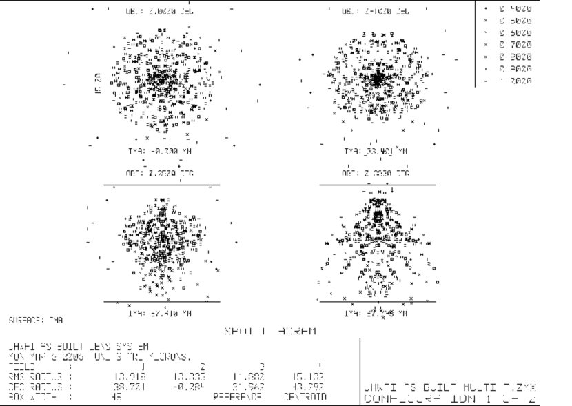
The optical design was optimized for the 0.45 - 1.0 m wavelength range with particular emphasis on the longer wavelengths, to offer the best optical performance where the new deep-depletion CCDs have their strongest competitive advantage. Over this range, the chromatic aberrations of the lens system are not significant relative to the typical seeing so that very broad filters can be used for search programs. Fig. 2 shows a geometric spot diagram of the optics, at wavelengths from 0.4 m to 1.0 m. Some of the 0.4 m spots are outside of the 3 pixel (0.7) box, while for the other wavelengths, the spots are all within that box. Fig. 3 shows the rms spot sizes integrated over the bandpasses of the ”grizy” filters listed in Table 2. The performance in the ”g” filter is not as good as in the other filters of our broad-band filter set, due to the poor performance of the optics at 0.40 m.
The optics design was optimized for 0∘C and 0.6 atm ambient atmospheric pressure, the average conditions on Mauna Kea. The performance of the optical system remains well within specification over the expected temperature range on Mauna Kea ( -5∘C to +5∘C).
The lenses were fabricated by Janos Technology, Inc. The typical lens specifications were a diameter tolerance of 0.1 mm, center thickness tolerance of 0.15 mm, edge thickness variation of 0.025 mm, and surface polish of 40/20. Surface irregularities of two interference fringes (at 0.63 m) over the full clear aperture of 93% of diameter against a testplate were acceptable. Small-scale irregularities were specified to be less than 1/6 fringe over any interferometer aperture of typically 80 mm diameter, the size of interferometer available to the lens manufacturer.
NOTE: Fig. 2 should be placed here.
NOTE: Fig. 3 should be placed here.
4 Mechanical Design
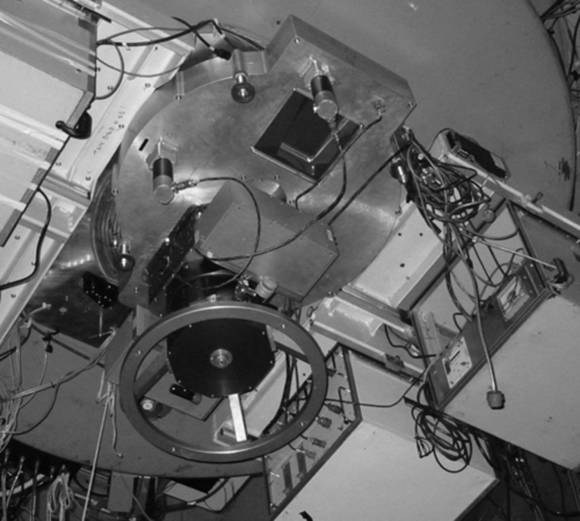
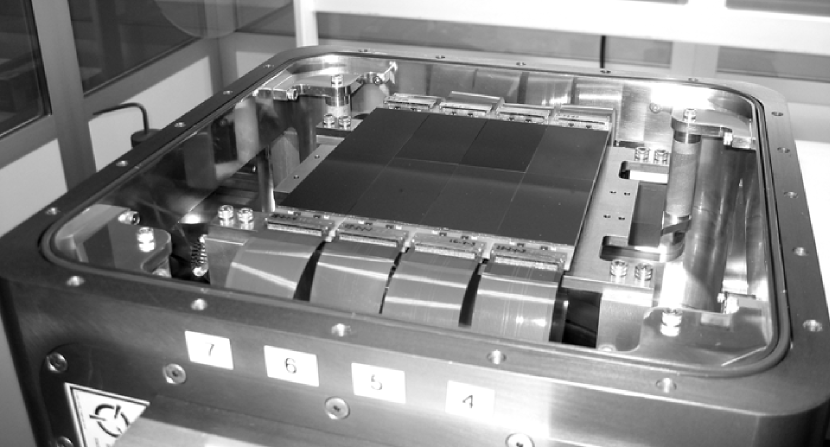
The housing of the UHWFI (Fig. 4) mounts directly to the Cassegrain rotator flange of the UH 2.2 m telescope (Fig. 5). On the top side of the housing, the lens cell is mounted and protrudes as far into the primary mirror baffle cone as is possible without substantial vignetting of the light path. On its bottom side, it interfaces to the refurbished dewar of the UH 8K camera, whose dewar window is the last element of our optical system, the field flattener lens. The housing contains the filter and shutter wheels and their motor and drive gears, as well as access ports for filter changes and the installation of the polarizer rotator HIPPO.
The UHWFI has five major mechanical components:
-
•
The focal reducer main lens group oil filled cell
-
•
The filter wheel and rotary shutter assembly
-
•
The interface to the 8K dewar including the field flattener lens that serves as the dewar window
-
•
A side access port for the HIPPO polarizer unit
-
•
The refurbished 8K CCD camera dewar
NOTE: Fig. 4 should be placed here.
NOTE: Fig. 5 should be placed here.
While the position of the filters is not in itself very critical, the filter and shutter wheel housing must be very stiff to support the lens mount and the dewar within tight tolerances imposed by the optical power of the field flattener dewar window. The housing for the filter and shutter wheel is fabricated from two thick aluminum plates, milled out to provide space and attachment points for the two wheel mechanisms, and also for weight reduction. An essential component in our design is the hollow central post in the filter and shutter wheel housing around which the co-axial filter and shutter wheels rotate on large diameter Kaydon ”Really Slim” X-contact ball bearings. This post is the only rigid support for the UH 8K camera on the side of the optical axis facing the wheels (left of the lens assembly in Fig. 4). Without this central support, an excessive wall thickness for the wheel housing would have been required to meet the rigidity requirements.
5 Detailed Design of Oil-Filled Lens
The lens cell relies on the proper centering of the lens outer diameters relative to the optical surfaces without any provisions for adjusting the centering of the lenses in the cell. This design approach required a 25 m centering precision from the lens manufacturer, which was achieved. The differential shrinkage of aluminum relative to the glasses used between the fabrication temperature (20oC) and the operating temperature (0oC) is of the same order as the alignment tolerances and was accounted for in the design of the lens cell. We are using a design similar to that used for cryogenic lenses (Hodapp et al., 2003) and support the lenses radially against two hard reference surfaces using an opposing spring loaded plunger to maintain contact with the reference surfaces in any orientation of the instrument. Prior to applying the spring preload, the lenses are not tightly constrained radially, so that they can be easily installed.
Axially, the lenses are spaced by thin (50 m) spacers, as explained above and as seen in Fig. 5. Both sides of the lens stack are axially loaded by compressed flexible Viton O-rings that also serve to seal the immersion oil cell. This arrangement avoids tight fits during assembly of the lenses and minimizes the potential for damaging the lenses, in particular the very fragile S-FPL51Y lenses, during installation.
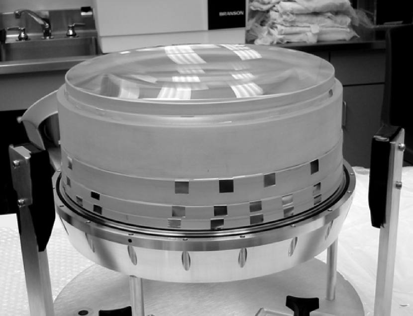
The focal compressor main lens group is assembled by first stacking the lenses upside down on the front ring of the lens assembly (Fig. 6). During the initial stack-up, the lenses are only roughly centered. After stacking, the body of the lens cell is lowered over the stack and closed, but not yet axially compressed. The lens cell is then put on its side with the two radial hard points on the bottom, so that the individual lenses will slide by 1 mm into contact with the radial support points. Next, the preload springs are installed and preloaded to keep the lenses positioned radially. Finally, the axial lens cell screws are tightened to compress the O-ring, which then define the lens positions axially and provide the main oil seal. Finally, the radial preload screw ports are sealed. The compression of the O-rings was measured and the spacing between the 6-lens group and the field flattener lens was adjusted in a final machining step to give the proper spacing of these two components.
NOTE: Fig. 6 should be placed here.
The lens system can be used in this dry condition, even though without the index matching oil, ghost imaging is more severe and the throughput is lower. Only after a successful test run at the telescope and full verification of the optical performance did we flood the cell with the index-matching oil.
NOTE: Fig. 7 should be placed here.
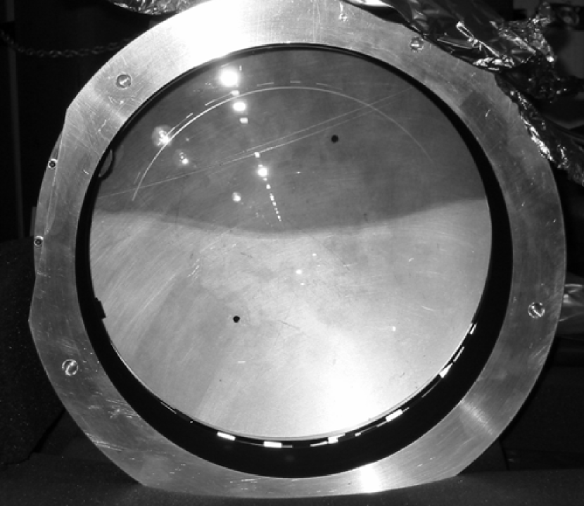
Fig. 7 shows the lens cell during the oil filling procedure. The optical axis is pointed horizontally. The index matching oil is being supplied from the lowest side of the cell and is drawn up into the lens gaps by capillary force. The supply of oil is adjusted for a very slow fill, taking about 20 hours to complete, so that the accidental inclusion of bubbles can be avoided. The image shows the lens about half filled. The reduction in the number and intensity of reflections and the substantial increase in overall throughput is clearly visible.
When the lens is filled with enough oil to fully penetrate the inter lens spaces, a bubble of air is left in the remaining volume of the lens cell. This compressible air volume is important to accommodate changes in the oil volume due to temperature changes. While this air bubble is free to move within the lens cell in response to changing orientation of the instrument, the surface tension at the oil-air interface prevents this large bubble from entering the narrow (50 m) spaces between the lenses.
6 Filter and Shutter Wheel Design
The filter wheel in UHWFI carries six filters of dimension 165165 mm and up to 15 mm thickness; the nominal filter thickness in UHWFI is 10 mm. This large wheel is driven by a Geneva drive conceptually similar to those developed by Bell et al. (1998) for some of the cryogenic instruments built at the IfA.
The advantages of this design are that it can be fully fabricated in-house, that it allows loose tolerances between the wheel and the drive, and does not pose difficult motor control requirements. Used in conjunction with a spring-loaded detent, it nevertheless achieves very high positioning precision. Similar again to the cryogenic mechanisms designed for other instruments, the wheel position is encoded by small magnets inserted into the wheel, and their magnetic field sensed by Hall effect sensors on the wheel housing. To facilitate the exchange of filters, the filters are individually mounted in cassettes that allow their handling without contact to the optical surfaces. The filter wheel housing has an access port (Fig. 4 and Fig. 5) so that filters can be exchanged easily while the instrument is mounted at the telescope.
The UHWFI is equipped with a newly designed large (diameter 71 cm) rotary sector blade shutter. The shutter blade is made of a lightweight aluminum honeycomb disk with outer diameter of 71 cm and inner diameter of 24 cm with a single machined 120∘ sector cutout. This design results in a low inertia, but still self-supporting blade. The shutter sector wheel is carefully balanced with a counterweight.
The shutter wheel is co-axial with the filter wheel. Stacking these two large wheels on top of each other offers significant design advantages over the combination of a filter wheel and a conventional linear shutter. The shutter is driven by a stepper motor (Phytron ZSH57) via a 5 mm pitch, 15 mm wide timing belt with a gear reduction of 11:1 under the control of a Galil motor controller. Position feedback is via embedded magnets in the shutter blade sensed by Hall effect sensors (from F. W. Bell).
The shutter is triggered by the rising edge of a TTL signal generated by the CCD readout Leach controller. This design was chosen for software compatibility with the existing UH CCD cameras. The shutter opens with a rapid acceleration phase of the shutter blade, essentially the maximum torque acceleration profile that the motor can supply. The acceleration phase is completed before any of the shutter blade edges intersect the optical path. While crossing the optical path, both in opening and closing direction, the shutter blade rotates at constant angular velocity. The shutter blade then decelerates again and comes to a standstill in the open position. The closing of the shutter is triggered by the trailing edge of the TTL signal from the CCD controller and proceeds similar to the opening phase.
Due to its large size and inertia, the shutter is not designed for short exposures. The shortest possible exposure time, limited by the mechanical properties of the shutter is about 1 s. The exposure times were calibrated using observations of bright stars. Above nominal exposure times of 2 s, the effective shutter open time is 0.25 s shorter than the nominal exposure time set by the duration of the CCD controller TTL signal.
7 Dewar Window
The last lens element is a field flattener lens that is required to compensate for the substantial field curvature of the original Ritchey-Chretien telescope optics and of the focal compressor lens group. To minimize the number of optical surfaces, this last lens also doubles as the dewar window. Since is is subject to high atmospheric pressure forces, we only support this lens axially on a (soft) O-ring that gets compressed by several millimeters when the dewar is evacuated. The compression of the O-ring under atmospheric pressure of 0.6 atm was measured and the design spacing adjusted to give the proper spacing of the field flattener lens relative to the focal compressor 6-lens group and the detector.
The large dewar window lens cools radiatively into the dewar when it is cold. To avoid condensation problems on its front surface, the inner volume of the UHWFI between the compressor lens group and the dewar window lens, including the filter wheel and shutter assemblies, is constantly being flushed with dry nitrogen from the dewar boil-off.
8 Control Electronics
The UHWFI control electronics operates the stepper motors for the filter and shutter wheels, and reads back home position information from the Hall effect sensors. It consists of a Galil Motion Control Inc. DMC-2120 2-axis Stand-Alone Motion Controller connected through a Galil ICM-2900 Interface Module to two Phytron Inc. ZSO MINI Bipolar Stepper Motor Driver Modules, stepper motor incremental encoders and an IfA built multi-channel Hall effect sensor support board. The host computer communicates with the motion controller via ethernet to initiate shutter or filter wheel actions or to obtain position information.
The Phytron drive modules generate the phased pulses required to move the Phytron Inc. ZSH 57 stepper motors from a dual output +62 V DC power supply. The signals from the two ZHS 57 stepper motors’ integrated incremental encoders are used to complete the DMC-2120 motion controller’s feedback control loop. The motion controller also sets the acceleration, deceleration, and maximum speed of the motors.
Hall effect sensors are used to determine positions by detecting small rare-earth magnets embedded in the shutter and filter wheels. One sensor is used to locate the ”home” or closed position of the shutter. Three sensors and associated magnets are used to uniquely identify each of the eight filter wheel positions. The IfA built multi-channel Hall effect sensor support board (same design as for the NIRI instrument (Hodapp et al., 2003)) provides precision stable voltage to the sensors and to on board voltage comparators as well as gain, filtering and conversion of the sensor signals. A Burr-Brown INA141 instrumentation amplifier provides gain and converts the differential sensor signals to single ended signals. The buffered signals are then sent to the external A/D converter of the Galil controller. The Hall effect sensors are used to initially find the wheel ”home” positions. Normal movements of the shutter or filter wheel are done by driving the motors with a predetermined number of steps and the Hall effect sensors are used only to verify the end positions.
9 The UH 8K CCD Camera
The UH 8K camera was first commissioned in the Spring of 1995 at the prime focus of the CFHT. The camera was initially equipped with 8 Loral/Fairchild 2K4K 15 m pixel CCDs and offered an image scale of 0.21″pixel-1 and a field of view of 0.47∘0.47∘ on this telescope (Luppino, Mezger, & Miyazaki, 1995). In addition, with the use of a field flattener as the camera entrance window, the camera has been used at the f/10 focus of the UH 2.2 m telescope, where the image scale is 0.14″pixel-1 and the field of view is 0.31∘0.31∘.
Because of budget constraints as well as our desire to deploy this camera as early as possible in order to take advantage of some scientific opportunities, we had elected at the time to use detectors that would not normally be considered ”science-grade.” These early detectors were operated in ”front-illuminated” mode resulting in a peak quantum efficiency of only 40% and with little or no response below 0.4 m. Furthermore, the CCDs had fairly high readnoise (10 e-), along with some serious charge transfer issues that required that we operate at a higher-than-usual temperature (-70oC). This then caused problems with spatially varying dark current. Finally, the readout time of the camera exceeded 7 minutes leading to a low duty cycle operation in practice.
We began a program to replace the UH8K camera CCDs with superb, science-grade detectors obtained as part of the UH-led MIT Lincoln Lab Consortium. The UH/MITLL project was initiated to design and build 2K4K 15 m pixel CCDs on high resistivity silicon and thin and back illuminate them to achieve the highest possible quantum efficiency over the entire optical region, but with particular emphasis on the red end (0.7 - 1.1 m) where the thicker detectors offered a real advantage over their typical thin CCD counterparts. The CCD that resulted from this effort was called the CCID-20 and these detectors have been incorporated into various large instruments including Subaru SUPRIME, Keck ESI, CFHT12K, Keck DEIMOS, ESO VLT, AAO/MSSSO WFI and UH AEOS spectrograph. They have achieved 2 e- readnoise at 100kpix s-1 readout speed, very good charge transfer efficiency, and a peak quantum efficiency at 0.6 m exceeding 90% with a QE at 1 m of 20%.
NOTE: Fig. 8 should be placed here.
We elected to upgrade the UH 8K camera following our experience building the nearly identical CFH12K (Starr et al., 2000). We rebuilt the cryostat and the focal plane (Fig. 8), and acquired new faster San Diego State University (SDSU2) controllers, identical to those used in CFH12K. With these improvements, we expected to see a substantial gain in overall performance: 7x reduction in readout time, a reduction by a factor of 3-5 in readout noise, and, on average, a factor of 2 improvement in quantum efficiency, with a larger improvement at the long wavelength end. Also, the operating temperature of the new CCDs is lower and therefore, dark currents should no longer be an issue.
NOTE: Table 2 should be placed here
The UHWFI is now equipped with a set of broad-band g, r, i, z, and y filters closely matching those planned for the Pan-STARRS project, as well as narrow-band H and [SII] filters. In addition, a wide V+R filter is being used for asteroid searches.
After the refurbishment of the UH 8K camera with new CCDs and a new set of readout electronics, the readout time is now 60 s and the total overhead over the shutter open time is 63 s per exposure. Quantum efficiency is greatly improved, as are the cosmetics of the devices and the dark current. The UH 8K camera is prepared for the installation of additional guide CCDs, if the need for such guiding becomes important, at this time, however, we are relying of open-loop tracking of the telescope.
The UH 8K user interface is a version of the ”detcom” detector controller software and its ”director” command line user interface originally developed for the CFH12K camera (Starr et al., 2000). The control of the filter wheel and shutter wheel was integrated into the ”director” user interface.
At this time, we don’t have any guiding of the telescope during the exposure. However, with the new telescope control system, the UH 2.2 m telescope tracks well enough for exposures of up to about 5 minutes. The image quality achieved by UHWFI is limited by the performance of the telescope optics. These suffer from complex aberrations that have a strong component of astigmatism. In practice, most observers focus the telescope to the best compromise focus where the images appear nearly round, but are slightly blurred beyond what seeing would produce. The telescope focus depends on temperature and telescope position, due to imperfections in the mirror support. In practice, focus adjustments are required about every 15 minutes. Also, astigmatism produced by focus errors is often hard to distinguish from telescope tracking imperfections. In combination, these characteristics of the UH 2.2 m telescope force observers to choose relatively short integration times. In addition, the thick deep depletion devices now used in UHWFI have a much higher cross section for cosmic rays, and therefore cosmic ray hits begin to limit the integration times. In practice, most observers use integration times of 3 to 5 minutes. This is enough to be sky background limited in all broad filters and to be marginally sky background limited in the H and [SII] filters. In such short exposures, and with proper attention paid to focus control, we are typically achieving image quality of 0.75 FWHM.
References
- Luppino, Mezger, & Miyazaki (1995) Luppino, G. A., Mezger, M. R., Miyazaki, S. 1995, IAU Symposium No. 167, ”New Developments in Array Technology and Applications”, eds. A. G. D. Philip, K. A. Janes and A. R. Upgren, Kluwer Academic Publishers, Dordrecht, p.297.
- Boulade et al. (2003) Boulade, O., Charlot, X., Abbon, P., Aune, S. Borgeaud, P., Carton, P.-H., Carty, M., Da Costa, J., Deschampls, H., Desforge, D., Eppellé, D., Gaillais, P., Gosset, L., Granelli, R., Gros, M., de Kat, J., Loiseau, D., Ritou, J., Roussé, J. Y., Starzynski, P., Vignal, N., & Vigroux, L. G. 2003, SPIE 4841, 72
- Starr et al. (2000) Starr, B. M., Luppino, G. A., Cuillandre, J.-C., Isani, S. 2000, SPIE 4008, 1022.
- Wei & Stover (1998) Wei, M. & Stover, R. J. 1998, SPIE 3355, 598.
- Bell et al. (1998) Bell, J., Douglass, J., Hodapp, K.-W., Robertson, L., Tokunaga, A. T., & Young, T. T. 1998, SPIE 3354, 1103.
- Hodapp et al. (2003) Hodapp, K. W., Jensen, J. B., Irwin, E. M., Yamada, H., Chung, R., Fletcher, K., Robertson, L., Hora, J. L., Simons, D. A., Mays, W., Nolan, R., Bec, M., Merrill, M., & Fowler, A. M. 2003, PASP 115, 1388.
- Lovell et al. (2000) Lovell, R., Sousa, E, Inouye, M., Maesato, K., Pickles, A., Tonry, J., Mizoshiri, A, Oshiro, P., Amano, L., & Motomura, H. 2000, Astronomical Data Analysis Software and Systems IX, ASP Conference Proceedings, Vol 216, editors Nadine Manset, Christian Veillet, and Dennis Crabtree, Astronomical Society of the Pacific, p. 275
| Optical Element | Material | Thickness | Radius-1 | Conic C. | Radius-2 | Diameter | Distance to next |
|---|---|---|---|---|---|---|---|
| Description | of Element | of Curvature | Constant | of Curvature | Element | ||
| Primary Mirror | Mirror | 0 | -12345 mm | -1.0535 | 2262 mm | 4640 mm | |
| Secondary Mirror | Mirror | 0 | -4198 | -3.604 | 556 mm | 5012 mm | |
| Lens-1 | S-FPL51 Y | 39.0 | 313.7 | 0 | 840.5 | 320 mm | 0.05 mm |
| Lens-2 | S-FPL51 Y | 39.0 | 840.5 | 0 | -1200 | 318 mm | 0.05 mm |
| Lens-3 | S-LAL10 | 15.0 | -1195 | 0 | plano | 316 mm | 0.05 mm |
| Lens-4 | S-BSM81 | 15.0 | plano | 0 | 325.0 | 314 mm | 0.05 mm |
| Lens-5 | S-FPL51 Y | 30.0 | 325.0 | 0 | 840.5 | 296 mm | 0.05 mm |
| Lens-6 | S-FPL51 Y | 30.0 | 840.5 | 0 | -2195 mm | 176.1 mm | |
| Filter | BK7 (nominal) | 10.0 | plano | 0 | plano | 26.2 mm | |
| Lens-7 | S-TIM2 | 15.00 | -3000 | 0 | 325.0 mm | 32.8 mm |
| Bandpass | ||
|---|---|---|
| g | 402 | 552 |
| r | 552 | 691 |
| i | 691 | 818 |
| z | 818 | 922 |
| y | 948 | 1060 |
| H | 652 | 661 |
| 667 | 677 |