22email: burigana@iasfbo.inaf.it
Zodiacal Light Emission in the Planck mission
Abstract
Context. The Planck satellite, scheduled for launch in 2007, will produce a set of all sky maps in nine frequency bands spanning from 30 GHz to 857 GHz, with an unprecedented sensitivity and resolution. Planets, minor bodies and diffuse interplanetary dust will contribute to the (sub)mm sky emission observed by Planck, representing a source of foreground contamination to be removed before extracting the cosmological information.
Aims. The aim of this paper is to assess the expected level of contamination in the survey of the forthcoming Planck mission.
Methods. Starting from existing far-infrared (far-IR) models of the Zodiacal Light Emission (ZLE), we present a new method to simulate the time-dependent level of contamination from ZLE at Planck frequencies.
Results. We studied the possibility of Planck to detect and separate the ZLE contribution from the other astrophysical signals.
Conclusions. We discuss the conditions in
which Planck will be able to increase the existing information
on the ZLE and IDP physical properties.
This work is done in the framework of the Planck/LFI activities.
Key Words.:
Interplanetary Medium – Infrared: Solar System – Submillimeter – Methods: numerical – Space vehicles: instruments – (Cosmology): Cosmic Microwave Background1 Introduction
The ESA Planck satellite 111http://www.rssd.esa.int/planck (Tauber 2003), scheduled for launch in 2007 222 While this paper was at the end-stage of the editorial process, the launch has been posponed to 2008. This will not affect the results in this paper. , is a full-sky surveyor dedicated to cosmic microwave background (CMB) and millimetric (mm) and sub-mm astronomy. It is a third generation microwave mission, after the NASA COBE and WMAP missions. The surveyor will observe the sky through a 1.5 m Gregorian aplanatic telescope carrying two instruments on the focal surface operating at the frequency bands centred at 30, 44, and 70 GHz (Low Frequency Instrument, LFI; Mandolesi et al. 1998) and 100, 143, 217, 353, 545, and 857 GHz (High Frequency Instrument, HFI; Puget et al. 1998). Planck will be injected in a Lissajous orbit around the Sun-Earth Lagrangian point L2 of the Sun-Earth system at a distance of Km AU from the Earth, from which it will observe the microwave sky for at least 15 months, necessary to complete two surveys of the whole sky with all the receivers. The LFI beams are located on the Planck telescope field of view in a ring with a radius of about 4∘ around the telescope line of sight (LOS) pointing at a scan angle from the satellite spin axis. The HFI beams, located closer to the centre, may be also at few degrees from the LOS. In the simplest scanning strategy, the spin axis, chosen pointed in the opposite direction from the Sun, will be kept parallel to the Sun-spacecraft direction, re-pointed by once an hour ( per day) in order to follow the revolution of the L2 Lagrangian point, and will spin at 1 RPM. Planck will scan the sky in nearly great circles approximately orthogonal to the ecliptic plane at a rate of 24 circles per day, each circle being scanned consecutively 60 times per hour. In this way Planck will produce at least two full sky maps for each frequency channel with an unprecedented resolution (FWHM from to ) and sensitivity (in the range of mJy on a FWHM2 resolution element). Although the detailed scanning strategy is currently under study (Dupac & Tauber 2005), its general properties imply that only objects located at from the Sun will enter the large circles traced in the sky by the main beams. Solar System objects then will be observed nearly in quadrature with the Sun i.e. within few degrees from a solar elongation of .
Why would a cosmological mission like Planck consider the Solar System in its scientific program? How should Solar System studies take advantage from a mission like Planck? A valuable contribution has been provided by the COBE mission to solar system studies (Kelsall et al. 1998). The scanning strategy of Planck assures that all the Solar System components located outside the Earth Orbit, except Mars, will enter at least once into the field of view of the surveyor during the mission. In this way point-like Solar System objects (external planets; Burigana et al. 2001 , Page et al. 2003, Schaefer et al. 2004, asteroids; Cremonese et al. 2002, Schaefer et al. 2004, comets) and the thermal emission of the diffuse interplanetary dust will represent foregrounds which have to be detected and properly removed in order to avoid the introduction of systematic errors in the cosmological measures (Maris, et al. 2003; Maris et al. 2004a).
The Zodiacal Light Emission (ZLE) due to thermal emission from the Interplanetary Dust Particles (IDPs) is the far-IR counterpart of the familiar Zodiacal Light due to scattering of the solar light by IDPs. Most of the properties of the ZLE below 300 m have been studied by IRAS (Wheelock et al. 1994), COBE (Kelsall et al. 1998) and ISO (Reach et al. 1996, 2003). Peaking at m, the ZLE is one of the major contributors to the sky background in the far-IR domain at low ecliptic latitudes. A first detection in the band has been assessed by Fixsen & Dwek (2002) using yearly averaged COBE/FIRAS data. Even a quick look at the data reported in Kelsall et al. (1998) and Fixsen & Dwek (2002) allows us to predict a contribution of ZLE in the 857 GHz channel of Planck of MJy/sr. It is evident that at the Planck lowest frequencies its contribution is much weaker than the Galaxy emission. On the other hand, at the Planck intermediate and high frequencies the ZLE is significantly weaker than the Galactic emission only at low Galactic latitudes while it is comparable to it outside the Galactic plane (for example, near the poles the Galactic emission is MJy/sr at 857 GHz). The expected ZLE contribution is larger than the instrumental noise at the Planck highest frequencies. Therefore, a careful analysis of the ZLE in the Planck data is required. Since the ZLE varies over angular scales it can be properly studied by working at a resolution of . At this scale the expected sensitivity per FWHM2 at 857 GHz at the end of the mission is MJy/sr (Lamarre et al. 2003). The extrapolated background from the Galaxy, representing the main large scale background component at this frequency, is MJy/sr. Because of the different tilt on the ecliptic of the Galactic plane and of the IDP cloud, for most of the scan circles observed by Planck, the sky position of the maximum of the ZLE will fall close to that of the minimum of the Galactic emission. In this case the ZLE is extrapolated to be about half of the Galactic emission. Of course one may wonder whether ground-based or balloon born CMB experiments may have been able to detect such a contribution. Looking at some of the most recent balloon-borne experiments, ARCHEOPS (Benoit et al. 2003) has constructed maps by bandpassing the data between 0.3 and 45 Hz, corresponding to about 30∘ and scales, respectively. MAXIMA (Lee et al. 2001) covered the multipole range or angular scales smaller that . The CMB power spectrum of BOOMERANG (Netterfield et al. 2002) covers multipoles from to , equivalent to angular scales . From ground based experiments, DASI (Pryke et al. 2002) measured the power spectrum for or angular scales less than . Among these experiments it seems that only ARCHEOPS is able to detect the large scale brightness variation connected with the ZLE. We then expect that the ZLE will be observable as an excess of signal superimposed on the Galaxy or it may be considered as a source of systematics in studying the large scale Galactic emission.
Our strategy, in line with past studies, exploits the existing far-IR observations, included in models, to derive the spatial distribution of the ZLE and to extrapolate its Spectral Energy Distribution (SED) at Planck frequencies. We take as a reference the yearly averaged values of Fixsen & Dwek (2002). Our starting point to model the spatial distribution of the ZLE, the work of Kelsall et al. (1998) for the ZLE based on the COBE data (hereafter indicated as the COBE-model), has many similarities with the IRAS model by Wheelock et al. (1994). It describes in detail the emissivity of the IDP cloud, assumed to extend up to AU from the Sun, for wavelengths up to about 300 m. According to the COBE-model four components contribute to the ZLE: the dominating smooth component, the Earth orbit locked ring of dust (or circumsolar ring), the trailing blob, and three bands of dust.
In this work only the standard IDP component has been considered. The analysis of the plausible, but not yet determined, contribution from the Kuiper Belt dust grains (Landgraf et al. 2002) will be the subject of another work.
With respect to other foregrounds usually considered in CMB studies, the ZLE (as the other Solar System objects) is peculiar, depending for its surface brightness not only on the pointing direction but also on the instantaneous position of the observer within the Solar System. Galactic and extragalactic foregrounds are generated by sources located so far from the observer that parallactic effects due to the motion of the observer within the Solar System are negligible compared to the instrumental resolution of CMB observatories. On the contrary, since the observer is located within the Solar System, the orbital motion about the Sun leads to changes in the ZLE brightness distribution as a function of the pointing direction. This underlines the relevance of studying the ZLE not only on maps but also on time ordered data streams (TODs). Moreover, the accurate simulation of observations for a satellite mission like Planck cannot be based on maps since the details of the orbit will have to be considered in addition to the usual scanning law.
The main aim of this work is to contribute to the following subjects: i) to define a representation method for the ZLE suitable for map based CMB mission simulators, with particular relevance for the Planck mission; ii) to determine suitable approximations (like scaling frequency laws) for the simulation of this component in the framework of the Planck simulation pipeline; iii) to determine to what extent the ZLE will impact the Planck survey; iv) to determine if it will be possible to separate the contribution of the ZLE from the data produced by the Planck mission in a self-consistent manner (i.e. reducing as much as possible the introduction of priors based on results from other missions in the Planck data processing pipeline); v) to explore the possibility of Planck to produce useful scientific results about the ZLE at frequencies barely explored in the past.
The paper is organised as follows. In Sect. 2 we briefly review the present knowledge about the ZLE. Sect. 3 describes the framework of our simulations, mainly based on the model of Kelsall et al. (1998), and the details of our numerical code discussing its main assumptions in the light of recent theoretical results. In Sect. 3.1 we present a series expansion of the ZLE spatial dependence that can be useful for many simulations and data analysis applications. In Sect. 4 we describe the main results of these simulations (mainly in form of TODs and maps) and compare the ZLE contribution to those expected from the Galactic emission. Sect. 5 is devoted to the separation of ZLE in the Planck data. Particular care is given to the analysis of the systematic effects in the differential approach for ZLE separation. Our main results and conclusions are summarised in Sect. 6.
2 Physical and geometrical properties of ZLE
To assess the expected errors in predicting the ZLE surface brightness at Planck frequencies from a model based on far-IR and IR data we review some theoretical concepts needed to link the ZLE model, and in particular the COBE-model, to the optical properties and the size distribution and other physical properties of the IDPs. In sub-mm and mm bands the dominant emission mechanism from IDPs is thermal emission of IR radiation driven by solar heating. The most general expression for the brightness averaged over the bandwidth and the beam, detected in a radiometric channel of frequency on-board a space-born experiment produced by a given population of IDP grains, representing a component of the IDPs cloud is
| (1) |
here is the grain size, the frequency, is an observing direction, the distance from the observer along , the position of the observer respect to the Sun, the position within the Solar System respect to the Sun along the line of sight, is the instrumental frequency response, the beam response, is the thermodynamical temperature for grains in the population , the blackbody emissivity and is the absorption coefficient for the population of grains, the size distribution for grains. A rigorous calculation of this integral is difficult since it requires the knowledge of many poorly constrained quantities. Alternatively effective models, such as the COBE model, are used in place of Eq. (1). We discuss here the relation between the two approaches. Let us assume that: i) the size distribution and the grain optical properties do not depend on , , with the spatial distribution of grains; ii) the beam is symmetrical and it does not depend on within the frequency bandwidth of each channel ; iii) the beam is small compared to the typical angular scales over which the ZLE varies. With these assumptions Eq. (1) simplifies to
| (2) |
where is a color correction which takes into account the averaging over the frequency weighted by the instrumental response (see Sect. 2.2),, is the optical density for the given dust component, is an emissivity correction related to the size distribution and composition of grains. For multifrequency observations, is usually normalised to a reference frequency, . For example in Kelsall et al. (1998) is normalised to the value it has in the COBE/DIRBE 25 m ( GHz) channel. Note that such kind of normalisation of implies a corresponding renormalisation of the optical density in Eq. (2). In principle it would be possible to compute and then from Mie theory assuming appropriate grain shapes and composition and using commonly available software (Bohren & Huffman 1998), as done recently in the study by Reach et al. (2003) of the ZLE emissivity at m. However, the composition and shape of IDP grains in the size range relevant at Planck frequencies are only poorly known. We prefer to determine at Planck frequencies comparing theoretical estimates with the existing COBE/FIRAS data, as detailed in the next section.
| f | |||
|---|---|---|---|
| [GHz] | [MJy/sr] | [MJy/sr] | |
| 30 | 0.0000 | 0.0006 | 0.001 |
| 44 | 0.0000 | 0.0013 | 0.002 |
| 70 | 0.0000 | 0.0032 | 0.004 |
| 100 | 0.0001 | 0.0064 | 0.009 |
| 143 | 0.0002 | 0.0129 | 0.018 |
| 217 | 0.0012 | 0.0291 | 0.041 |
| 354 | 0.0083 | 0.0755 | 0.110 |
| 545 | 0.0458 | 0.1751 | 0.262 |
| 857 | 0.2742 | 0.4229 | 0.648 |
2.1 Estimating at Planck frequencies
We estimated in the relevant range of frequencies comparing the expected ZLE yearly averaged from the COBE model with the existing surface brightness measures at Planck frequencies from Fixsen & Dwek (2002) based on COBE/DIRBE and COBE/FIRAS data. However, given the uncertainties in the interpretation of these data, other extrapolation methods are possible. According to the main result of Fixsen & Dwek (2002), the SED of the ZLE Smooth component is approximately similar to a blackbody with K scaled by an emissivity factor nearly constant for m and scaling as at longer wavelengths:
| (3) |
As evident from this analysis of COBE/FIRAS data (Fixsen & Dwek 2002), the accuracy of the recovered ZLE spectrum is good at frequencies higher than about 800 GHz while the error bars significantly increase at lower frequencies, where most of the Planck frequency channels are located. This leaves space for further improvement in the field with Planck. After estimating the yearly average surface brightness from the COBE model, , assuming we obtain
| (4) |
The resulting estimated , normalized to 1 at GHz, are reported in Table 1 with the expected yearly average surface brightnesses. is approximated in the range of frequencies of interest by
| (5) |
2.2 The colour correction
The colour correction in Eq. (2) takes into account the effect of the frequency instrumental response within the bandwidth. At Planck frequencies, most of the ZLE is due to IDPs with temperatures exceeding K; within the bandwidth of each Planck frequency channel, their emission integrated along the line of sight can be approximated by a power law with spectral index and normalisation (from here we will omit the pointing dependence to simplify the notation). In addition, within a frequency band , where is the spectral emissivity correction and accounts for the spatial distribution expected from grains emitting as blackbodies and can be separated into a pure spatial dependence and a pure frequency scaling. Here normalisations are defined to match the values of and for and the overall turns to be . Therefore, by imposing
| (6) |
and Taylor expanding in the - space about the brightness and the emissivity correction, we obtain
| (7) |
together with and . The validity of the approximation represented by Eq. (2) is then verified.
We assess the value of needed to compensate the fact that in Eq. (2) the integration over the bandwidth in Eq. (1) has been neglected. In addition we want to assess the level of uncertainty in the correction induced by the uncertainty in the prediction.
We restrict ourselves to the illustrative case of a simple top-hat window with relative bandwidth . For Planck for GHz and for GHz. We tested that for different reasonable shapes of the results do not change significantly. Under these conditions, for
| (8) |
where is the normalisation for the spectral window.
For numerical estimates, assuming and , we obtain and . For the case of a frequency-independent , and we find and . Leaving to vary within unit changes by only . Thus it will be possible to avoid applying this small correction in the numerical estimates presented in the remaining part of this paper.
Note that in Kelsall et al. (1998) the colour correction is defined as a correction for the instrumental response when a blackbody is observed. For this reason the colour correction is parametrised as a function of the blackbody temperature which is a function of the position along the line of sight, so that the argument of the pointing direction integral in Eq. (2) would have to be scaled by the spatial dependent . However, at our frequencies the bulk of the blackbody emissivity comes from grains emitting not too far from the Rayleigh-Jeans limit, i.e. with a frequency power law scaling (within our rather limited bandwidth) with a power law index largely independent of . In this case the two definitions for are equivalent.
3 The model and the numerical code
The surface brightness calculated for a given frequency band is
| (9) |
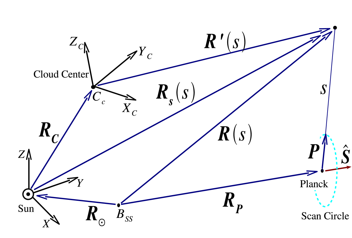
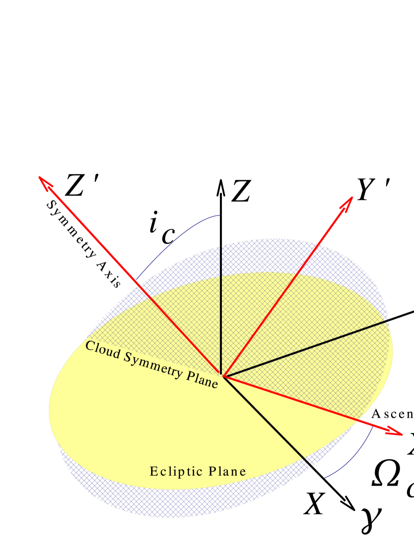
Here denotes the position of the Sun within the Solar System and the index denotes the specific component either the dominating smooth component, the Earth orbit locked ring of dust, the trailing blob, or one of the three bands of dust. According to the discussion in Sect. 2, in Eq. (9) we separate the calculation of the spatial distribution of the ZLE assumed to be a blackbody from the more uncertain emissivity correction. The detailed COBE MODEL has been already described in the literature (Kelsall et al. 1998; Fixsen & Dwek 2002) and only few details need to be reviewed. The relevant geometry of ZLE observations is shown in Fig. 1: the Sun (or the barycentre of the Solar System ), the position of the L2 point, the spacecraft (in this case Planck) position , the centre of the distribution of dust related to the component of interest, , and the related vectors drawn between these points. The most important among them are: the position of a point at distance from the spacecraft along the pointing direction : ; its position with respect to the Sun, , and to the centre of the cloud defined by : . In addition we define . , , denote the Cartesian components of and , , those of . The model specifies the 3D dust density distribution of each component, factorised into a radial dependence and a vertical dependence, as the heliocentric dependence of the mean dust temperature. In this way, for each component it is possible to define a proper reference frame about which the cloud has cylindrical symmetry. Its origin coincides with the centre of the cloud and its midplane with the equatorial plane of the cloud; it may be rotated, tilted and shifted with respect to the ecliptic plane.
We have implemented the COBE MODEL in a FORTRAN-90/95 program called FS_ZOD (Flight Simulator - Zodiacal Light Emission) embedded in a supporting OCTAVE pipeline (Maris 2001). The code was originally designed as a module of the Planck Flight Simulator but can be used for any other experiment. Since the scalings are largely uncertain it is left to the user to apply the proper one to the output of these programs. In this work we use the code to study the time dependence in the signal acquired by Planck for the nominal scanning strategy (Dupac & Tauber 2005) and a recently simulated spacecraft orbit (Hechler 2002) and to predict the ZLE induced perturbation in Planck data. We choose to express our results in terms of brightness (MJy/sr), as for IRAS and COBE data.
3.1 Series expansion of the ZLE spatial dependence
Simulators for CMB missions and the related data-reduction pipelines, such as those realized for Planck, are largely based on maps. A map allows a good representation of the sky brightness as a function of the pointing direction. This procedure neglects the time-dependent information on the Planck position within the Solar System, leading to a loss of information when Solar System components are considered. The ground segment of a mission like Planck would be able to handle and analyse TODs as well as maps obtained from them (Pasian & Sygnet 2002; van Leeuwen et al. 2002; Challinor et al. 2002). A TOD of ZLE would allow an exact representation of any seasonal dependence. However, TODs are large and their realization requires an effective scanning strategy and satellite orbit, possibly accommodated during the mission, so that the exchange of simulated data in the form of TODs is not practical for the data analysis of a multichannel, high-resolution mission like Planck. We implement a method able to 1. properly represent seasonal effects in a large set of mission configurations; 2. possibly be applied to other missions; 3. exploit the (cylindrical) symmetries in the components of the IDP cloud.
We propose to generalise the concept of pixelized map. A pixelized map is usually defined as the values assumed by a given observable on a set of pixels ordered according to the adopted pixelization scheme. In this contest we can introduce a generalisation of this concept by defining a pixelized “map” as a list of values assumed by a given observable on a set of pixels which are also functions of the positions of the Sun and of the Spacecraft (Planck in our case) within the Solar System. In a reference frame (r.f.) in which the displacements of the Sun and spacecraft positions are just small fractions of their averaged positions, the pixelized “map” can be replaced by the series expansion of the observable about the average positions of the Sun and the Spacecraft.
Then, denoting with , the reference positions of Spacecraft and Sun about which the series expansion is performed, we have
| (10) |
In the numerical computations for Planck we exploit values of the displacements along each direction up to about AU for and up to about AU for , about a factor of two wider than any reasonable displacement for a mission that will reside near L2. In addition, we adopt in this work the HEALPix scheme (Górsky et al. 2005) with “ring” ordering, widely used in the CMB community.
We have tested that in the case of the ZLE it is preferable to expand not the brightness spatial distribution but its logarithm in power series. Then, denoting by the brightness integral for a given frequency channel , component and pixel index (connected to the pointing direction by the mapping scheme) as a function of and we adopt the following decomposition
| (11) |
where and , , are exponential functions of polynomials of and . In order to achieve an accuracy better than for more than 96% of the pixels, we verified that 333The remaining pixels will have an accuracy worse than 1% (the worst accuracy recorded being 2.5%) in the case of a displacement of the spacecraft and of the Sun at the limits of the region for which the expansion is calculated. it is sufficient to consider the following terms of the series expansion:
| (14) |
where and , are the Cartesian components of and ; the , , and terms denote the first, second and third order coefficients, respectively, and repeated indices , , = , , are summed. The number of independent coefficients is 3 for and , 6 for and , 9 for and . The other coefficients are simply obtained by index permutations. Then, for each pointing direction a total of 38 independent components has to be computed. These coefficients can be determined by solving by least squares a sufficiently large set of independent equations obtained by exploiting different combinations of displacements , (in the case of Planck about 100). Metrics are then applied to assess the quality of the data generated with this series expansion compared to the data generated by the full simulation (for further details see Maris et al. 2005). A dedicated support IDL library to handle the files of expansion coefficients, named ZLE_IDL, has been created (Maris et al. 2004b).
4 Results
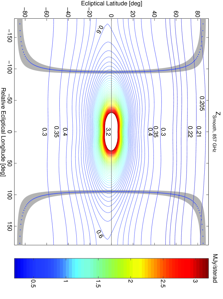
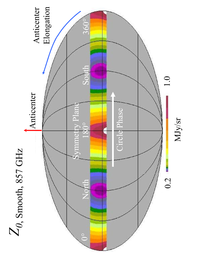
The contour plot in Fig. 3 is an example of for the Smooth component contribution calculated for the 857 GHz frequency channel assuming . According to the discussion in Sect. 2, and the expected observed surface brightnesses are about 2/3 the values reported in the plot. The figure represents the variation of as a function of the pointing direction for a given combination of ad . Contours are drawn for , 0.22, 0.23, 0.24 0.25, 0.30, , 3.2 MJy/sr. Given the cylindrical symmetry of the IDPs, the pointing in the plot is expressed as a function of the ecliptical latitude and of the relative ecliptical longitude, i.e. the difference between the longitude of the pointing direction and the longitude of the solar direction which is at the centre of the plot. The blue dotted line represents the path described by a Planck beam at the centre of the field of view assuming the nominal scanning strategy and the grey band represents the region observed by considering all the Planck beams. Having the IDPs cloud a cylindrical symmetry, and the symmetry reference frame being nearly equivalent to the Planck comoving reference frame, for the nominal scanning strategy both the signal contour levels and the region observed by Planck will shift approximately in the same way when the spin axis is repointed. Consequently, only a small fraction of the possible pointings in the cloud reference frame will be observed by Planck. In the case of more complicated scanning strategies, such as those including slow spin axis precession about the Sun - Satellite direction or slow oscillations above / below the ecliptic (Dupac & Tauber 2005), the scanning path will be shifted normally and along the ecliptic plane. Slow spin axis precession or oscillations with semi-amplitudes of , such as those considered for the Planck scanning strategy, will change the path reported in the plot by with a resulting signal difference more sensitive near the ecliptic plane ( MJy/sr). However for any reasonable scanning strategy the envelope of all the possible scanning path will be only twice or three times wider than the grey band in the figure.
The tilt of the cloud with respect to the ecliptic plane and parallactic effects induced by the motion of the spacecraft with respect to the cloud introduce small modifications in the pattern of the contour lines and between the signal TODs from different scan circles.
| [MJy/sr] | [MJy2/sr2] | [MJy2/sr2] | [MJy2/sr2] | [MJy2/sr2] | [MJy2/sr2] | |||
|---|---|---|---|---|---|---|---|---|
| 8010 | 1.60E-1 | 4.72E-2 | 1.12E+3 | 3.4 | 6.25E-2 | 1.87E-3 | 6.9E-4 | |
| 4.0 | 5141 | 2.01E-2 | 4.62E-2 | 9.76E-1 | 0.43 | 7.57E-3 | 1.49E-3 | 9.8E-4 |
| 3.0 | 4524 | 2.38E-2 | 4.55E-2 | 5.29E-1 | 0.52 | 4.75E-3 | 1.40E-3 | 1.1E-3 |
| 2.0 | 3591 | 1.52E-2 | 4.38E-2 | 2.12E-1 | 0.35 | 8.10E-4 | 1.18E-3 | 1.3E-3 |
| 1.0 | 2007 | 7.58E-3 | 3.27E-2 | 3.49E-2 | 0.23 | -3.94E-4 | 9.09E-4 | 2.0E-3 |
| 0.9 | 1772 | 7.20E-3 | 2.95E-2 | 2.56E-2 | 0.24 | -4.56E-4 | 8.67E-4 | 2.1E-3 |
| 0.8 | 1495 | 5.42E-3 | 2.48E-2 | 1.76E-2 | 0.22 | -3.27E-4 | 8.09E-4 | 2.4E-3 |
| 0.7 | 1220 | 3.98E-3 | 1.95E-2 | 1.17E-2 | 0.20 | -1.91E-4 | 7.68E-4 | 2.8E-3 |
| 0.6 | 881 | 2.32E-3 | 1.44E-2 | 7.25E-3 | 0.16 | -8.37E-5 | 6.96E-4 | 3.4E-3 |
| 0.5 | 505 | 1.54E-3 | 1.06E-2 | 4.17E-3 | 0.14 | 8.33E-5 | 6.67E-4 | 4.7E-3 |
| 0.4 | 177 | 7.58E-4 | 5.51E-3 | 2.39E-3 | 0.14 | 9.41E-5 | 5.72E-4 | 8.5E-3 |
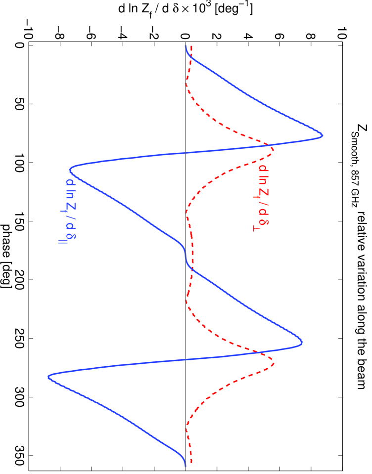
TODs may be generated at any desired sampling rate, for example from that corresponding to 1/3 of the instrumental FWHM resolution to resolution. It is important to estimate the error in the computation of the signal in the TODs when the true convolution with the beam about its centre direction is replaced by the convolution with a “pencil beam”. Denoting with and the displacements from the beam centre respectively along the direction parallel to the scan circle oriented in the scan direction and normal to it towards the Sun, we compute the derivatives along these directions. They are displayed in Fig. 6, where and are plotted for different positions along the scan circle of Fig. 3 at 857 GHz and for the Smooth component. For the Smooth component deg-1 and deg-1 (here is in MJy/sr). For displacements less than arcmin the error introduced by this approximation is at most 0.03% along and 0.05% along . These error estimates can be linearly rescaled to larger displacements and such as those associated with the sky pixelization.
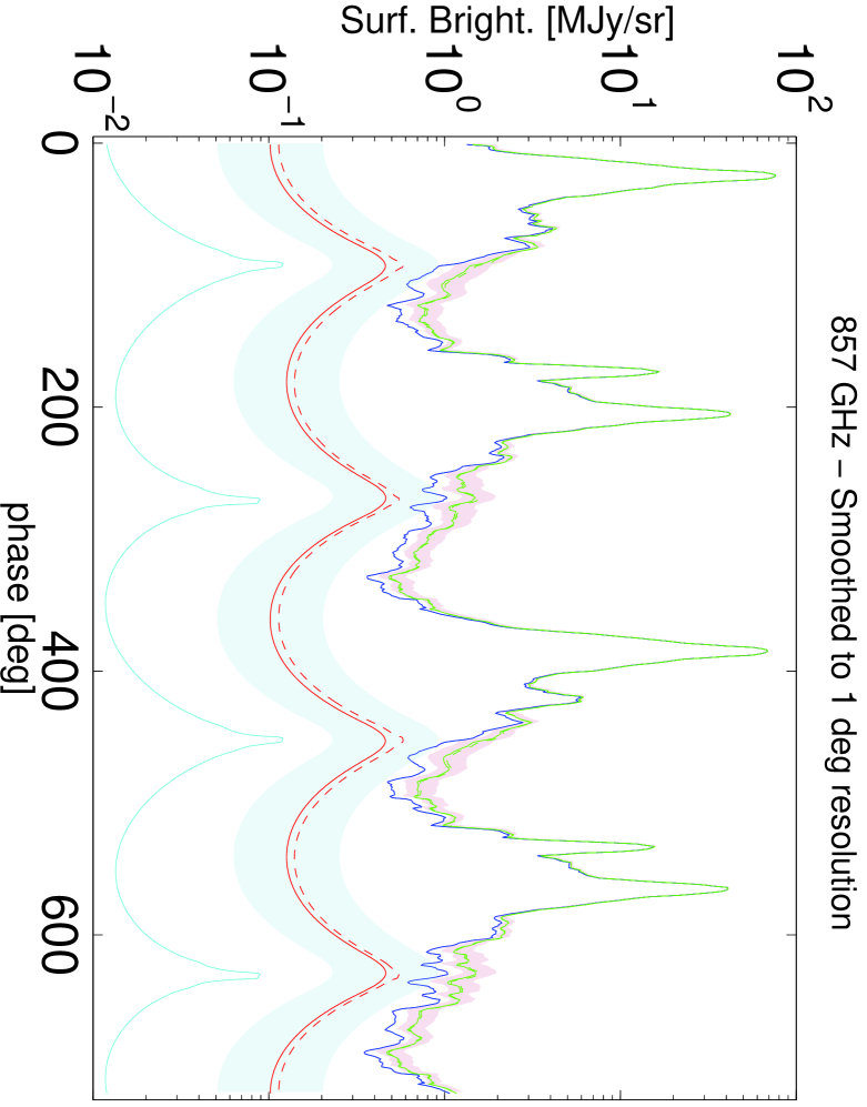
Fig. 4 represents a portion of a TOD, with the associated uncertainty, simulated at 857 GHz without noise and with a sampling at a resolution of 1∘. It is the generated sampling from Fig. 3 scaled with . In the figure we report for comparison our preliminary estimate of the sum of the other ZLE components. Comparing the TOD with the corresponding contour map one sees that maxima in ZLE (red lines in the figure) occur when the beam crosses the plane of the IDPs cloud, slightly below the ecliptic plane for the considered case. Minima instead occur when the beam is approximately orthogonal to it. For Planck, the spin induced modulation of the ZLE signal has a main period equivalent to 2 cycles per minute (for the nominal spin rate of 1 r.p.m.). In a single scan circle, two maxima occur when the beam crosses the ascending node and the descending node between the scan plane and the IDPs cloud plane. Since the plane is tilted on the ecliptic, Fig. 3 allows us to predict the occurrence of asymmetries between the two peaks even if the scan circle is centred at the antisolar direction. The secondary components contribute to the bulk of the ZLE.
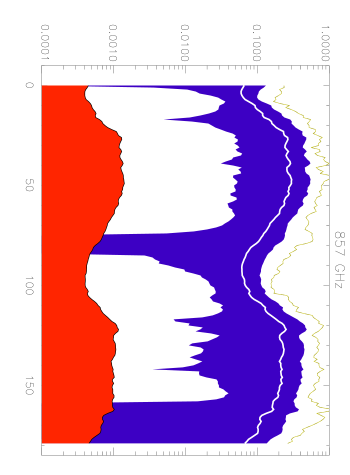
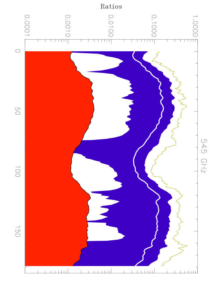
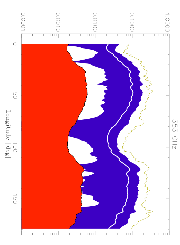
To compare the expected ZLE signal with the Galactic foreground, TODs for the Galactic emission have been generated and averaged within a circle of radius. Galactic emission TODs are generated using Galactic maps obtained by Schlegel et al. (1998) with the prescriptions in Finkbeiner et al. (1999) for the scaling of the Galactic surface brightness as a function of frequency and pointing direction. Due to the tilt of the ZLE symmetry plane over the Galactic plane, the ZLE at 857 GHz is comparable to the Galactic emission at low ecliptic latitudes where the Galaxy is weak, contributing a peak surface brightness of MJy/sr, or approximately half of the weakest Galactic signal along that circle. Of course, the ecliptical longitude of the spin axis about which the scan circle is drawn will affect the relative contribution of the ZLE with respect to the Galaxy. For this reason, we report in Fig. 5 the variation of the ratio (where denotes the Galactic surface brightness – we consider here only the dominant dust emission) with the ecliptical longitude of the spin axis, for three different Planck frequencies and for circular patches of radius. The white-full line represents the ratio averaged over the given scan circle. The black band is the range of such variation, while the highest ratios expected for each scan circle are represented by the gray-dashed line. At 857 GHz for about half of the scan circles the expected peak ZLE is roughly half of the Galactic dust emission. Since the ZLE frequency scaling is not much different from that of the Galactic dust emission, also at the lower frequencies considered here its peak contribution to the sky emission is still larger than some ten percent of the Galaxy for most of the circles. This contribution is compared to the instrumental sensitivity. The gray band at the bottom of each frame in the figure represents the ratio between the instrumental noise, , and the Galactic dust for circular patches, averaged over a scan circle. On average, the ZLE contribution is largerly above the instrumental noise from 857 GHz to 353 GHz.
4.1 Time dependence characterization
The time dependence in the ZLE signal is characterised by the short term modulation shown in Fig. 4 and by a long term modulation derived from the effective motion of the spacecraft within the IDP cloud determined by the L2 orbital motion around the Sun and the spacecraft Lissajous orbit around L2.
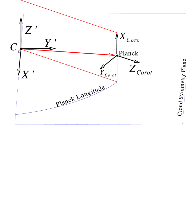
The effects of the spacecraft motion are better represented in the reference frame defined by the cylindrical symmetry of the cloud and corotating with L2. To understand the long term modulation we have to consider the followings:
-
1.
The tilt of the IDPs fundamental plane over the ecliptic, which introduces a seasonal modulation in the signal seen by a spacecraft bound stay near L2;
-
2.
The ellipticity of the L2 orbit about the Solar System barycentre moving the spacecraft with respect to the centre of the cloud;
-
3.
Since the centre of the Smooth component does not coincide with the Sun, even a circular orbit around the Sun will induce changes in the spacecraft position with respect to the cloud centre of symmetry;
-
4.
Following its Lissajous orbit around L2 the spacecraft changes its height over the cloud symmetry plane.
The spacecraft position is then , with the position of the L2 point and the Lissajous orbit. For typical Planck Lissajous orbits around L2, is less than a few Km.
Due to the ellipticity of the Earth orbit, the distance of L2 from the Sun varies during the year by a 3%, i.e. of AU Km.
Being on the ecliptic, the L2 point changes its distance from the bulk component symmetry plane due to its tilt. This induces at maximum a vertical oscillation of Km. In addition the Sun is off-centred with respect to the centre of IDP cloud of the Smooth component km.
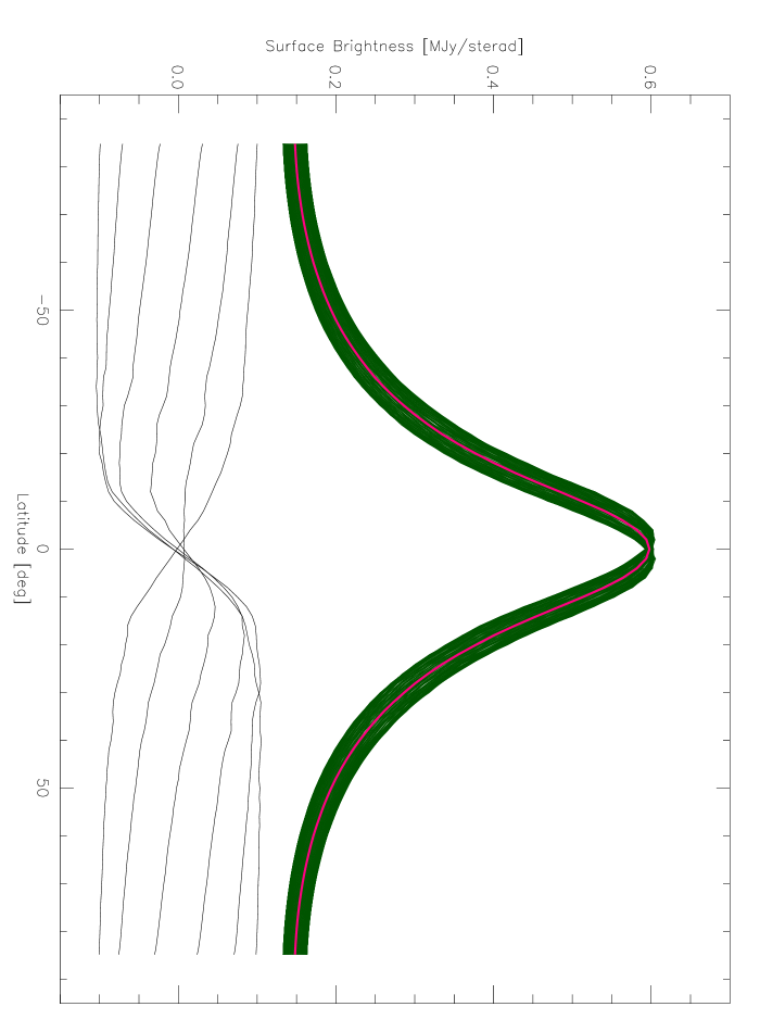
The largest seasonal dependence is due to the tilt of the IDP fundamental plane. It affects mainly the value of the minima of the surface brightness observed by Planck. When the spacecraft is below the fundamental plane of the IDP cloud the optical depth towards the North ecliptic Pole is larger than that towards the South ecliptic Pole, resulting in a North/South asymmetry in the minima. As Planck orbits about the Sun, the spacecraft goes toward the node between the ecliptic and the IDP cloud symmetry plane, crosses it and enters a region where the symmetry plane is below the ecliptic. So, with time the North/South asymmetry goes to zero and then reverts its sign. The tilt of the symmetry plane over the ecliptic does not significantly affect the level of maximal ZLE surface brightness observed by Planck, while it affects the location of the maxima and the shape about the peak. Fig. 8 represents the modulation of the minima and the North/South asymmetry for a 857 GHz horn supposed to be aligned with the telescope optical axis. The full curve represents the surface brightnesses looking to the North ecliptic Pole. The dashed curve represents the surface brightnesses looking towards the South ecliptic Pole. The relative seasonal modulation is about .
In Fig. 7 we compare the yearly averaged ZLE surface brightness with the daily surface brightness at 857 GHz. The variation of the Planck position with respect to the symmetry plane of the Smooth component introduces variations of up to in the surface brightness with respect to the yearly average surface brightness, almost independently of the considered frequency and . For typical Lissajous orbits, the variation of the Planck height with respect to the cloud symmetry plane is of the variation induced by the tilt of the symmetry plane on the ecliptic but with a periodicity of 6 months and phase displacement with respect to the yearly periodicity related to the exact launch date. Therefore, about 10% of the above 10% variations of surface brightness induced by the effective Planck motion is introduced by the Lissajous orbit. Clearly, this is a second order effect for studies of the yearly averaged properties of the Smooth component, but it is still larger than the sensitivity of Planck TODs averaged over or resolution, as it will be discussed in Sect. 5. Secondary components contribute to about 10% of the global ZLE. Therefore, neglecting the Planck orbit may significantly reduce the accuracy with which these components can be studied. Finally, the differential approach to ZLE separation that has several advantages with respect to other approaches (see Sect. 5.4) exploits the variation of the ZLE during the mission. Neglecting the Lissajous orbit effect will result in an error of in this kind of analysis. Of course, the precise inclusion of the spacecraft position is not a concern from a computational nor practical point of view.
4.2 Frequency scaling for the spatial distribution
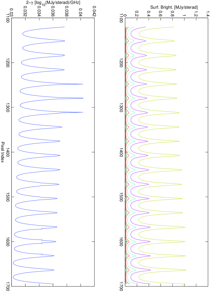
The frequency scaling for is a theoretical outcome of the model and can be used to check the extent by which it is possible to assume . To study the frequency scaling for the spatial distribution of ZLE, sets of have been generated for covering all the Planck frequency channels up to GHz, a fixed combination of and positions, , and scanning the sky in circles of increasing angular radius from to centred in antisolar directions. The corresponding data are plotted in the upper frame of Fig. 9, while the lower frame represents the spectral index obtained by fitting a power law dependence for the surface brightnesses obtained for a given pointing direction.
Note that the average is , close to the expected value . In addition, the spectral index is modulated with the pointing and is anticorrelated with the surface brightness, the higher spectral indices occurring for lower surface brightnesses. The amplitude of the modulation, however, is modest, in terms of peak-to-peak signal. The colour correction would be then insignificantly affected. The effect of a change of AU in the position of Planck over the ecliptic results in a which has negligible effects on too. Smaller variations occur shifting the Planck position in other directions. The same holds for a shift of the Sun position with respect to the centre of the cloud.
These results assure that a power law is an adequate approximation within each frequency band, but this is only approximately true considering the full range of Planck frequencies. For example, in the range the mean spectral index is 1.990 while in the range the mean spectral index is 1.928.
Assuming at GHz the same spectral index as at GHz, the relative error induced in the surface brightness prediction at 100 GHz would be . Therefore, a set of spatial templates, one for each frequency channel, has to be produced in order to simulate the spatial dependence of the ZLE with an accuracy of . On the contrary, by relaxing the required accuracy to , a spatial template at an appropriate reference frequency (for example at GHz) followed by a spatially independent frequency scaling can be used.
These effects, although very small, may be not negligible in CMB studies, that are mainly carried out at GHz requiring foreground removal with an accuracy better than .
| arcmin | Patches | Patches |
|---|---|---|
| 0.5 | ||
| 1.0 | ||
| 1.5 | ||
5 Separability of ZLE with Planck data
The ZLE represents a foreground contamination mainly relevant for the higher frequency channels of Planck. Its contribution has to be removed to accurately study the Galactic large scale structure and its frequency scaling. Given the weakness of the ZLE signal, the final separation quality will may rely on the prior information added to the system derived from other missions at IR bands, such as IRAS and COBE where the ZLE dominates the sky emissivity. We discuss here four different approaches to ZLE separation.
5.1 A test of a “blind” map-based approach
When ZLE is folded over a map, its histogram is strongly non-Gaussian, as for the Galaxy. In principle this suggests the possibility of obtaining a proper separation of the ZLE through blind component separation methods already used to analyze microwave maps.
We performed some numerical experiments with the FastICA code (Maino et al. 2002) applied to full-sky maps obtained by adding the ZLE and the Galactic emission. FastICA is a blind-separation method which usually uses as input maps at different frequencies that are linear combinations of signals, all non-Gaussian except for at most one. The code gives as output maps of the various signals. We exploited the two frequency channels at 857 GHz and 545 GHz and, as a test case, neglected the noise. Although in principle this method could be investigated, possibly by applying it to Planck channels combined with IR data, this test gives discouraging results. Likely this is due to the weakness of the ZLE emission and the fact that this code does not use any prior information about the ZLE spatial distribution. In addition part of this information is lost when passing from TODs to maps.
5.2 A “non-blind” map-based approach
An “ad hoc” strategy for ZLE detection and separation can use a prior information, derived from IR observations, on the spatial dependence of the ZLE. We developed a model for ZLE detection and separation based on the extrapolation of the geometrical information from COBE/DIRBE to Planck frequencies (or from any other reliable model), leaving as free parameters the emissivity corrections, , at Planck frequencies. The ability of Planck to measure the ZLE is then translated into its accuracy in the determination of at different frequencies.
A non-blind separation based on maps could be differently investigated taking as prior information the ZLE spatial dependence and the existing templates of the Galactic emission degraded to angular resolutions comparable with the scales of significant ZLE variations ().
For example, denoting with the map obtained from the observed signal minus its average, the Galactic emission template (or any other relevant background signal) minus its average, the template for ZLE spatial distribution minus its average and the template for noise spatial distribution minus its average for the considered scanning strategy and satellite orbit, then the map for the signal (minus its average) may be approximated with
| (15) |
where accounts for possible overall systematic scaling errors, both from calibration and frequency extrapolation, in the “Galactic” template. It is possible to attempt a minimisation of
| (16) |
where the sum is taken over all the pixel index of the map and is the noise variance at each pixel.
Assuming stationary noise equidistributed over the map, the minimisation provides the estimators for and
| (17) |
Here , , , , .
In addition, it is possible that the true scaling factor is not constant over the sky. To simulate this effect we replace a constant scaling with a normally distributed variable, with expectation and RMS .
We consider here an illustrative case with sensitivity per pixel MJy/sr, where the effective number of observations made during the mission which contributes to the pixel , , , at GHz, and a map sampled at resolution, and taking all the pixels in the map (i.e. including also regions where the Galaxy largely dominates) the RMS for is with a bias of the same order, while is recovered with an RMS accuracy of about but an excess bias of about . On the other hand, removing all the pixels where the signal from the Galaxy does not greatly exceed that of ZLE reduces the bias. Removing pixels for which the Galaxy exceeds the surface brightness of MJy/sr, and are recovered with a RMS accuracy of about 0.01 for and 0.05 for . Their expectations are very close to their input values, with biases of a few . (In the remain we consider limits of surface brightness at values exceeding MJy/sr). As can be seen, the accuracy of the method is very good.
On the other hand, any (positive or negative) residual contribution from the ZLE in the Galactic template from the data analysis of the IR data will be scaled to Planck frequencies and will introduce a systematic effect which will be correlated with the spatial template adopted in Eq. (16). This will result in biases in the recovered and values. An end-to-end evaluation of this effect, beyond the scope of this paper, would require to analyse in detail the mission and the data reduction procedure used to obtain each IR data set used in preparing the Galactic template. However, the results of this approach can be compared with the differential method described in Sect. 5.4 that automatically by-passes this problem.
| Freq | Minimum | Optimal | Min. | Max. |
|---|---|---|---|---|
| [GHz] | [MJy/sr] | [MJy/sr] | [MJy/sr] | |
| 857 | 0.022 | 6.5 | 2.3 | 26 |
| 545 | 0.017 | 2.0 | 1.0 | 8.3 |
| 353 | 0.011 | 0.50 | 0.20 | 2.0 |
5.3 A “total-power” TODs-based approach
The prior information derived from IR observations, discussed previously also can be applied to the time domain, taking also into account the time dependence of the spacecraft position within the IDP cloud.
In this approach the separation is based on the knowledge of the time dependence of the ZLE signal in TODs derived from the spatial pattern . Then, as before, we define an estimator of starting from the observed data and the known spatial pattern.
Again, denoting with , , , and the Galaxy, the ZLE, the noise and the signal (minus their average values over the mission), and neglecting systematic instrumental effects
| (18) |
This equation is analogous to Eq. (15) where is replaced by and maps are replaced by TODs. So and can be obtained from Eq. (17) but replacing with and maps with TODs. Note that in the case of stationary noise 444We consider in this work instrumental white random noise. Planck receivers are affected by -like noise that introduces long term correlations appearing as offsets in TODs (and as stripes in maps). On the other hand, destriping algorithms (see, e.g., Burigana et al. 1997) accurately remove this effect in the TODs (and in the maps)., uncorrelated with the signal, is constant all over the TOD and substitutions like are allowed 555This is not true for a map since in this case is a function of even for stationary white noise.. The surface in this case is similar to the case in Sec. 5.2, but here the sensitivity per pixel is constant MJy/sr. The final sensitivity of this approach is found to be similar to that found for the method in Sec. 5.2.
Consider the case in which the Galactic contribution is neglected in the fitting, as in Kelsall et al. (1998). Assuming stationary white noise, after minimisation of
| (19) |
the estimator formula is
| (20) |
Assuming that the noise is uncorrelated with the sky signal, the expectation for is
| (21) |
This simple estimator is then affected by a bias due to the correlation between and .
The bias is likely negligible for Kelsall et al. (1998) since in their case the ZLE signal is much larger than the Galaxy emissivity so that . But at 857 GHz we obtain MJy2/sr2, to be compared with MJy2/sr2 and MJy2/sr2, leading to a bias in . Such high bias such a small covariance comes from the fact that is of the same order of magnitude as . Selection of samples in order to reduce does not mitigate the problem. For example, removing all the samples where the Galaxy is larger than MJy/sr leads to MJy2/sr2, MJy2/sr2, MJy2/sr2, with a bias . Removing all samples where the Galaxy is larger than MJy/sr leads to MJy2/sr2, MJy2/sr2, MJy2/sr2, with a bias . As evident, the bias decreases when applying stronger cuts but it still remains significant (see Table 2, columns 1 to 6).
5.4 A “differential” TODs-based approach
Planck will scan the sky at least twice during the mission. Therefore, most of the sky directions will be observed at least twice with Planck in different positions within the IDP cloud. In the ideal case, the difference between these two measures will be due to the difference in the ZLE contribution that can be predicted from our model plus noise.
We denote with and the epochs of the first and the second observation of a region seen in the direction and with , (, or , or , ) the corresponding observed surface brightness total signal variations (ZLE spatial distribution or Galactic emission or noise) with respect to the mean. With these definitions the differential surface brightnesses will be
| (22) |
with the convention that and that and so on. The is defined now as
| (23) |
where is the RMS of the noise for the considered samples (for stationary noise ) giving
| (24) |
where and . The expectation for this estimator is
| (25) |
since, by definition, , we have for any pair of , giving
| (26) |
without any bias and without the need to use Galactic templates.
Applying the standard error propagation formula to Eq. (26) and considering Eq. (24), if the noise can be approximated as stationary, independent and Gaussian with variance , summing over all of the pairs we have
After some algebra we have
| (27) |
where is the number of independent pairs. Note that does not significantly depend on the adopted radius of the patch because of the invariance of the ratio.
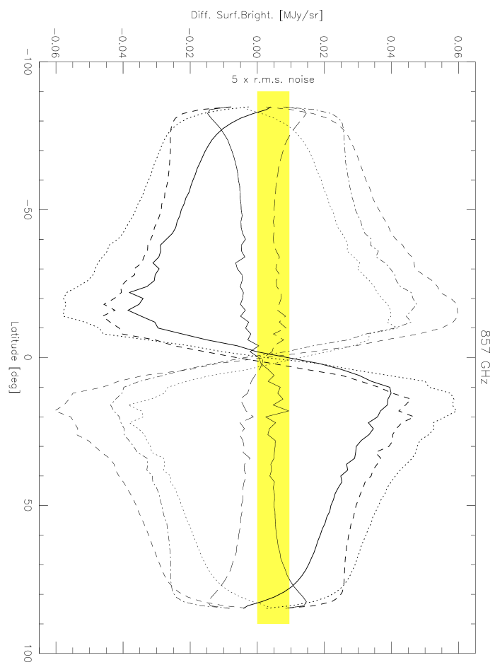
Fig. 11 represents the expected for , the nominal scanning strategy of Planck at 857 GHz, and a set of selected ecliptical longitudes of Planck 666 In this calculation it is assumed that Planck is orbiting about the L2 point according to the nominal orbit expected for a launch in February 2007. Changes in this orbit will only slightly change the results discussed above.. Note that the peak differential signal is about from the ecliptic plane. The signal is calculated averaging over independent circular patches of in radius. The difference between the first and the second scan never exceeds 0.06 MJy/sr, then being a effect. However, when compared to the sensitivity expected in this frequency channel (represented at by the gray band), this signal is clearly detectable, particularly when the spacecraft is located at ecliptical longitudes of and , where a particularly good peak is expected. For a threshold , a clear detection of the differential signal is expected for . In case of , the ratio is so good as to open the possibility to also improve the parameters of the geometrical model, to study possible spatial dependences in , and to identify secondary components.
The noise statistics “per patch” (RMS and patch–to–patch correlation) depend on the method used to assemble samples from TODs to form patches of sky. To determine a simple statistic for the noise, we construct patches i) of fixed solid angle (namely, circular patches with radius, , of or ), ii) observed in both surveys with a significantly large number of samples coadded so as to avoid a significant difference in the effective weight of each sky direction in the two surveys (in order to assure a similar coverage of the same patch in the two surveys and smooth out possible particularly bright pixels – see also the discussion in Sect. 5.5.1), iii) taken contiguously in time () in each survey, and iv) avoiding the presence of overlapping patches. These constraints only slightly reduce the number of samples used in the analysis. After two surveys the average instrumental noise RMS on a single squared pixel with side equal to arcmin for the reference frequency channel at 857 GHz is 43 mJy. Composing these pixels to form circular patches of radius , the noise per patch is
where the factor comes from the fact that we are considering the difference between the values observed in the same patch in the two surveys taken separately (the variance of samples entering in the patch can be neglected according to condition ii)).
Columns 7 to 9 of Table 2 shows the statistics for the simulated scan at 857 GHz. The last column gives the expected 1 error on determination according to Eq. (27) with the expected level of noise.
Accepting all the sky samples at 857 GHz a RMS accuracy should be expected. The effect of cuts based on the Galactic surface brightness is shown in Table 2. By considering regions where the Galactic signal is smaller than MJy/sr ( MJy/sr) the accuracy reduces to (). On the other hand, for MJy/sr (relevant to reduce the impact of the relative calibration uncertainty, see Sect.5.5.3) the number of independent pairs decreases from to with , only slightly degraded with respect to the full sky analysis. The cut changes the sign of column 7 due to the tilt of the ecliptic plane, so that the ZLE and its variation is stronger where the Galaxy is weaker.
A similar analysis carried out at 545 GHz and 353 GHz gives analogous results on the scaling introduced by the surface brightness cut. By considering the sky regions identified by the MJy/sr at 857 GHz, with the same kind of analysis we find and at 545 GHz and 353 GHz, respectively.
5.5 Systematic effects in the differential approach
The most important source of error in the determination of is the bias induced by when it is comparable to . In this subsection the main sources of this bias are discussed.
5.5.1 Error Induced by Sky Sampling
In the differential approach presented in the previous section we cancel out the Galactic signal. This is a good approximation provided that the patch is equally sampled in each of the two surveys, implying . In reality, uncertainties in the spacecraft attitude reconstruction and in pointing maneuvers and, in particular, the displacements between the positions of the various samples taken in the two surveys will imply that the same patch is sampled in a different manner in each survey. An estimate of the maximum displacement between the position of a given sample in the first survey and the nearest sample taken in the second survey is given by the maximum between half of the spin axis displacement ( arcmin) and half of the angular sampling along the scan circle (, equivalent to arcmin at 857 GHz). The pointing accuracy for Planck is expected to be better than arcmin () for each sample (Burigana et al. 2001; Puget et al. 2001), a value smaller than the above estimate 777 In addition, while finalizing this paper, a significant improvement in the Planck star trackers was achieved leading to an expected pointing accuracy of few arcsec (see, e.g., Harrison & van Leeuwen (2005)). . Denoting with the pointing direction neglecting the displacements discussed above and with the effective pointing direction in the -th survey, the displacement is . We are interested in which depends on the combined displacements . Then , leading to a bias in the determination of of the order of .
If we assume that does not correlate with the Galactic emission or the ZLE, as is reasonable, no bias will be introduced. On the other hand, this effect will degrade the sensitivity by
| (28) |

where the variance is taken over the considered patch. We assume that is a bivariate random variable, normally distributed, with null expectation and isotropic covariance matrix , with the displacement variance uniform all over the sky. Therefore, in the above linear approximation, for each patch of samples the averaged surface brightness difference will be normally distributed with null expectation and variance
| (29) |
where the variance is taken over the considered patch and the factor 2 is due to the differential approach. For patches of (or ) radius, and samples of arcmin along the scan circle and arcmin transversally to it, (or ). For a simple determination we can assume that where is the typical solid angle of the sample, so that
| (30) |
From the simulations of Sect. 5.4 for patches of (or ), arcmin and applying a cut to remove patches where the Galaxy is stronger than 1 MJy/sr, we estimated a of (or ). We simulate in detail the effect of a random pointing modelled as above. We obtain that, apart from a few spikes that are easily filtered, the perturbation induced by the Galaxy is in general small. The total error is dominated by the bias until strong cuts are applied. The total error does not change with . The total pointing error is small. The results are shown in Table 3 reporting both the expectation and the variance of . The expectation is small while the RMS of the error is consistent with Eq. (30). The RMS from our MonteCarlo simulation scales quite well with . In summary, the random pointing error does not seriously limit the recovery of .
We consider here the requirement ii) of Sect. 5.4. We could have a different number of samples () in the same patch in the two surveys both because of the different samples at the boundary of the patch and because of the result of the effective scanning strategy. This implies a difference in the average Galactic signals obtained in the two surveys, related to the fluctuations of the Galaxy within the patch. With a simple algebra it is straightforward to derive that in this case the variance of the induced in our differential approach is
| (31) |
Eqs. (29) and (31) clearly show the relevance of the constraint ii) of Sect. 5.4 in the construction of the patches. An approximate comparison between Eq. (29) and Eq. (31) gives . As , we have even for . This implies that the effect associated with could significantly impact the final result, if not taken properly into account in the data analysis. Of course, it has no physical meaning to have a sensitivity degradation in the presence of an increased number of observations in one of the two surveys. In reality, the above computation underlines the relevance of properly assembling the “elementary” samples in the two surveys in order to count the signal from the same sky direction the same number of times in each of the two averages over the considered patch.
The worst effect of systematic pointing errors would occur in sky regions with bright point-sources. It would then be preferable to remove pixels affected by bright sources before of the computation of the averages of the signals in each patch in order to manage only with signals dominated by the diffuse components.
An example of an intrinsic source of systematic pointing errors is the aberration of light. When not accounted for, the aberration due to satellite motion about the Sun may induce at most a pointing error of rad 0.7 arcmin, dominated by the Earth motion about the Sun. The factor of 2 comes from the fact that patches are acquired at most at about of longitude when the orbital motions are toward opposed directions in the sky. This effect may introduce an important bias; however since the spacecraft velocity is known within Km/sec or better, the effect may be removed by correcting the selected pointings.
5.5.2 Doppler shift
The relative motion of the satellite with respect to the Sun induces a Doppler shift in the Galactic signal observed during each of the two scans. The effect will be and assuming the surface brightness variation will be . Even for in the range , . Assuming and taking the statistics from the signal correlations from Table 2, then MJy2/sr2 equivalent to a bias . However the application of 4 MJy/sr cut will reduce this bias by an order of magnitude. Of course, a further relevant reduction (by a factor or 100) of this effect can be reached with a simple modelling of the Galatic emission spectral index (for example at % or 1% accuracy).
In addition, assuming the IDP cloud to be at rest around the Sun (neither shifting, nor rotating in time), the Doppler shift will affect the ZLE surface brightness too, so that a MJy/sr equivalent to a bias in of at most .
5.5.3 Calibration uncertainty
The impact of any absolute calibration error of Planck data uniform all over the mission is of simple evaluation. In the differential approach, any calibration uncertainty of this kind produces a null effect in the Galactic signal. The only final error will be a multiplicative uncertainty in the ZLE and then in given by , where is the relative uncertainty of the absolute calibration ( according to FIRAS absolute calibration accuracy from GHz to GHz).
The evaluation of the impact of calibration errors varying during the mission is more difficult (i.e. relative calibration errors). Clearly, the difference in the calibration errors in each patch in the two considered surveys produces systematic effects in our differential approach proportional to .
We evaluated the implications of random relative calibration errors. The relative calibration accuracy of Planck/HFI highest frequency channels is currently under definition. Pajot et al. (2000) (§ 3.3.6.1) reported a preliminary relative pixel-to-pixel calibration accuracy of . Piat et al. (2002) investigated HFI calibration with a kinematic dipole at frequencies at GHz and with Galactic templates at GHz. The authors reported a relative calibration accuracy on each scan circle of at 545 GHz and of at 353 GHz with suitable choices of the surface brightness cut.
Rescaling the error estimate by Pajot et al. (2000) from arcmin pixels to circular patches of radius, we find a relative accuracy, , of . The results of Piat et al. (2002) can be rescaled to the above circular patches considering that we have about scan circles per circular patch. In this way we estimate at 545 GHz and at 353 GHz.
We then consider in the range , so perturbing the simulated signal from each patch. The comparison between the estimation of obtained in the absence of this systematic error and by repeating the perturbed simulation described above for many thousands of realizations and for various Galactic cuts is shown in Fig. 12 for a particular case. As evident, at 857 GHz, assuming and Galactic cuts in the range MJy/sr we find a RMS error on of (with an expectation value of the residual bias of ).
For the RMS errors on are or respectively at 545 GHz or at 353 GHz for suitable Galactic cuts. Table 4 summarizes our results. The range of surface brightness cuts appropriate for each frequency allowing the above sensitivity spans about one order of magnitude. We verify that for the RMS error on scales linearly with at all frequencies.
Of course, the optimal Galactic surface brightness cut should be identified a posteriori according to the recovered value of and with a proper trade-off between the various systematic errors.
6 Conclusions
We presented an analysis to predict the level of contamination from the Zodiacal Light Emission (ZLE) in the survey of the forthcoming Planck mission and to evaluate the ability to extract the ZLE signal from the Planck data. This signal is used to gain more information about the ZLE physical properties.
Our starting point is the model of Kelsall et al. (1998) for the ZLE based on the COBE data describing in detail the emissivity of the IDP cloud for wavelengths up to about 300 m complemented by the recent result of Fixsen & Dwek (2002) on the spectral behaviour of the ZLE. According to the COBE model, four components contribute to the ZLE, the dominating smooth components on which this paper is focussed, the Earth orbit locked ring of dust (or circumsolar ring), the trailing blob, and three bands of dust.
With respect to other foregrounds usually considered in CMB studies, the ZLE (as the other Solar System objects) is peculiar, its surface brightness depending not only on the pointing direction but also on the instantaneous position of the observer within the Solar System. This underlines the relevance of a study of the ZLE not only on maps but also on time ordered data streams. Taking the average yearly position of Planck in the IDP dust cloud will result in a error in the ZLE surface brightness estimate, while neglecting the Planck orbit about L2 will imply a error in the ZLE surface brightness estimate. Since the ZLE differential approach separation exploits the variation of the ZLE surface brightness between the two surveys, neglecting the Planck orbit will introduce a non-negligible systematic error in this method. This will have a large impact on the study of secondary ZLE components, a natural extension of this work.
We have implemented the COBE model in a dedicated program that computes for a given list of values of , , and a set of parameters describing the properties of the ZLE component for which the calculation has to be performed. Of them, the emissivity correction for each component and for each frequency band is the hardest to extrapolate to Planck frequencies and it carries most of the physical information on the IDP population producing the bulk emission at these frequency bands. We then focused on the capability of Planck to recover . Since the scalings are largely uncertain, the code separately generates the surface brightnesses appropriate for each desired component. The outputs produced for the various components then can be easily combined according to the user need.
Since the TODs are large and their realization is strictly related to the effective scanning strategy and satellite orbit we also implemented an approximate, but accurate, method able to compress the , dependencies in TODs for the desired pointings in matrices of appropriate series expansion coefficients.
We investigated the possibility of obtaining a proper separation of the ZLE through a blind component separation method (FastICA) already used to analyse microwave maps, without obtaining encouraging results.
A non-blind separation based on maps has been investigated taking as prior information the ZLE spatial dependence and the existing templates of the Galactic emission degraded to angular resolutions comparable with the scales of significant ZLE variations. We considered here in detail the case of the HFI 857 GHz channel. In this case the main foreground is the dust Galactic emission. For appropriate Galactic surface brightness cuts ( MJy/sr) the value of recovered with this approach is in good agreement with the input one with an RMS absolute accuracy . On the other hand, any possible residual contribution from the ZLE left in the IR Galactic template adopted from their original data analysis procedure will be scaled to Planck frequencies and will introduce a systematic effect which will be correlated with the spatial template adopted in ZLE estimates, possibly resulting in biases in the recovered . A total power approach on TOD has been also investigated, providing similar results. These two methods require the use of low resolution Galactic templates.
To circumvent the need for Galactic templates and to better take into account the effects introduced by the varying spacecraft position, we have studied a differential approach exploiting the fact that Planck will scan the sky at least twice during the mission, staying in different positions within the IDP cloud. In the ideal case, the difference between these two measures will be due to the difference in the ZLE contribution that can be predicted from our model plus noise. We find a typical absolute RMS uncertainty on induced by the limited instrumental sensitivity of (1) at 857 GHz for suitable choices of surface brightness cuts (or and at 545 GHz and 353 GHz, respectively). For typical expected values of (, 0.26, 0.11 for 857 GHz, 545 GHz, 353 GHz) the Planck sensitivity will allow an recovery at 0.15%, 0.8% and 2.4% (1) accuracy at 857 GHz, 545 GHz and 353 GHz, respectively.
We investigated the impact of the most relevant systematic effects, pointing and sampling uncertainty, aberration of light, Doppler shift and relative calibration uncertainty. While the first four effects are expected to be significantly below the noise, the last effect is potentially the most critical one. For a relative calibration error RMS of on patches of radius, we find an absolute RMS error on of with only a weak dependence on the frequency in the range GHz, corresponding to relative errors on , , (, , ) respectively at 857 GHz, 545 GHz, 353 GHz for the most likely values expected on the basis of COBE/FIRAS data. This may ultimately determine the final accuracy of the ZLE extraction from Planck data.
A web page containing documentation, FITS files, and IDL routines to handle the series expansion for ZLE simulations is in preparation.

Acknowledgements
We warmly acknowledge the Planck collaboration teams for having provided us with instrument and mission details. We thank F. Boulanger and M. Juvela for constructive discussions and J.P. Bernard, G. Cremonese, M. Fulle, and G. De Zotti for encouraging and stimulating conversations. We acknowledge L. Abrami and C. Doz of the INAF/OAT for having supported the acquisition of bibliographic material. Some of the results in this paper have been derived using the HEALPix package (Górsky et al. 2005). We warmly thank the referee, W. T. Reach, for constructive comments and suggestions. M.M. acknowledges partial support by COFIN 2005 SubMM (prot.2004028417_003) SISSA / Trieste / Italy.
References
- (1)
- Benoit et al. (2003) Benoit, A., Ade, P., Amblard, A., Ansari, R., Aubourg, É., et al., 2003, A&A, Vol. 399 No. 3 p. L19
- Bohren & Huffman (1998) Bohren, C.F., & Huffman, D. R., 1998, Absorption and Scattering of Light by Small Particles John Wiley & Sons, ISBN: 0471293407, New York, USA
- Burigana et al. (2001) Burigana, C., Butler, C., Mandolesi, N., 2001, Planck/LFI Int. Note PL-LFI-PST-TN-023
- Burigana et al. (1997) Burigana C., Malaspina M., Mandolesi, N., et al., 1997, Int. Rep. TeSRE 198/1997, November, astro-ph/9906360
- Burigana et al. (2001) Burigana, C., Natoli, P., Vittorio, N., Mandolesi, N., Bersanelli, M., 2002, Exp. Astron., 12/2, 87, 2001
- Challinor et al. (2002) Challinor, A.D., Anthony, D., Mortlock, D.J., van Leeuwen, F., Lasenby, A.N., et al., 2002, MNRAS, 331, 994
- Cremonese et al. (2002) Cremonese, G., Marzari, F., Burigana, C., Maris, M., 2002, New Astronomy, (7/8), 483
- Dohnanyi (1969) Dohnanyi, J.S., 1969, J. Geophys. Res., 74, 2531
- Dohnanyi (1976) Dohnanyi, J.S., 1976, Lect. Notes Phys., 48, 187
- Dupac & Tauber (2005) Dupac, X., & Tauber, J., 2005, A&A, 430, 363
- Fixsen & Dwek (2002) Fixsen, D.J., & Dwek, E., 2002, Ap.J., 578, 1009
- Giese & Grün (1976) Giese, R.H., & Grün E., 1976, Lect. Notes Phys., 48, 135
- Górsky et al. (2005) Górski, K.M., Hivon, E., Banday, A.J., Wandelt, B.D., Hansen, F.K., et al., 2005, ApJ, 622, 759
- Grün et al. (2005) Grün, E., Srama, R., Krüger, H., Kempf, S., Dikarev, V., et al. 2005, ICARUS, 174, 1G
- Grün, Zook, Fechting & Giese (1985) Grün, E., Zook, H.A., Fechting, H., Giese, R.H., 1985, ICARUS, 62, 244
- Finkbeiner et al. (1999) Finkbeiner D.P., Davis M., Schlegel D.J., 1999, ApJ, 524, 867
- Harrison & van Leeuwen (2005) Harrison, D.L., & van Leeuwen, F., 2005, MNRAS, in press, astro-ph/0510345
- Hechler (2002) Hechler, M., 2002, ESA, Directorate of Technical and Operational Support, Ground System Engineering Department Herschel/Planck Consolidated Report on Mission Analysis, ESA Internal Report, Issue 2.0, FP-MA-RP-0010-TOS/GMA, June 26, 2002
- Ishimoto (2000) Ishimoto, H., 2000, A&A, 362, 1158
- Kelsall et al. (1998) Kelsall, T., Weiland, J.T., Franz, B.A., Reach, W.T., Arendt, R.G., et al., 1998, ApJ, 508, 44 (also astro-ph/9806250)
- Lamarre et al. (2003) Lamarre, J.M., Puget, J.L, Bouchet, F., Ade, P.A.R., Benoit, A., et al., 2003, New Astronomy Reviews, 47, 1017
- Landgraf et al. (2002) Landgraf, M., Liou, J.-C., Zook, H.A., Grün, E., 2002, AJ, 123, 2857
- Lee et al. (2001) Lee, A.T., Ade, P., Balbi, A., Bock, J., Borrill, J., et al., 2001, ApJ, 561L, 1L
- Maino et al. (2002) Maino, D., Farusi, A., Baccigalupi, C., Perrotta, F., Banday, A. J., et al., 2002, MNRAS, 334, 53
- Mandolesi et al. (1998) Mandolesi, N., et al., Planck/LFI a proposal submitted to the ESA
- Maris (2001) Maris, M., 2001, Planck/LFI - FS_ZOD: A Simulator of the Zodiacal Light Emission for the Planck Mission, 2001, Planck/LFI Int.Rep.: PL-LFI-OAT-TN-023, Issue 1.0
- Maris, et al. (2003) Maris, M., Burigana, C., Cremonese, G., Marzari, F., Fogliani, S., et al., 2003, Proc. of the XLVII National Conference of the Italian Astronomical Society, Mem.S.A.It. Suppl., 3, 318
- Maris et al. (2004a) Maris, M., Burigana, C., Cremonese, G., Marzari, F., Fogliani, S., 2004a, Proc. of the Planetary Science: Fifth Italian Meeting , 15 - 19 Sep. 2003, Gallipoli, Lecce, Italy, Eds. Blacno, A., Dotto, E., Orofino, V., p. 63 - 66
- Maris et al. (2004b) Maris, M., Fogliani, S., Burigana, C., 2004b, How to use the Zodiacal Light Emission Maps for Planck , Planck/LFI Int.Rep.: PL-LFI-OAT-TN-031, Issue 1.0, 2004, Dec
- Maris et al. (2005) Maris, M., Burigana, C., Fogliani, S., 2005, Simulation aspects on the ZLE modelling in the Planck mission, Int. Rep. IASF-BO 429/2005, October 7
- Netterfield et al. (2002) Netterfield, C.B., Ade, P.A.R., Bock, J.J., Bond, J.R., Borrill, J., et al., 2002, ApJ, 571, 604
- Page et al. (2003) Page, L., Barnes, C., Hinshaw, G., Spergel, D.N.; Weiland, J.L.; et al. 2003, ApJS, 148, 39
- Pajot et al. (2000) Pajot, F., and the Calibration Team, 2000, HFI Calibration Plan, Int. Rep. PL-PHZW-100061-IAS, Edition: 2, Revision: 0, 10/11/2000
- Pasian & Sygnet (2002) Pasian, F., & Sygnet, J.-F., 2002, Proc. of Astronomical Data Analysis II, Edts. Starck, J.-L., Murtagh, F. D. Proceedings of the SPIE, 4847, 25
- Piat et al. (2002) Piat, M., Lagache, G., Bernard, J.P., Giard M., Puget, J.L., 2002, A&A, 393, 359
- Pryke et al. (2002) Pryke, C. Halverson, N.W., Leitch, E.M., Kovac, J., Carlstrom, J. E., et al., 2002, ApJ, 568, 46
- Puget et al. (1998) Puget, J.,L., et al., 1998, Hight Frequency Instrument for the Planck mission, A proposal submitted to the ESA
- Puget et al. (2001) Puget, J. L., Lamarre, J.M., Sygnet, J.F., 2001, Planck/HFI Int. Note PL-HFI-IAS-TN-POINT002
- Reach et al. (1996) Reach, W.T., Abergel, A., Boulanger, F., Desert, F.-X., Perault, M., et al., 1996, A&A, 315, L381
- Reach et al. (2003) Reach, W.T., Morris, P., Boulanger, F., Okumura, K., 2003, Icarus, 164, 384
- Schaefer et al. (2004) Schaefer, B.M., Pfrommer, C., Hell, R., Bartelmann, M., 2004, astro-ph/0407090
- Schlegel et al. (1998) Schlegel, D.J., Finkbeiner, D.P., Davis, M., 1998, ApJ, 500, 525
- Tauber (2003) Tauber, J.A., 2003, Advanced in Space Research, 34, 491
- van Leeuwen et al. (2002) van Leeuwen, F., Challinor, A.D., Mortlock, D.J., Ashdown, M.A.J., Hobson, M.P., et al., 2002, MNRAS, 331, 975
- Wheelock et al. (1994) Wheelock, S.L., Gautier, T.N., Chillemi, J., Kester, D., McCallon, H., et al., 1994, IRAS Sky Survey Atlas Explanatory Supplement, JPL Pubbl. 94-11