∎
9, avenue du Colonel Roche, 31028,
Toulouse, France Tel.: +0033-5-61558561
Fax: +0033-5-61556651
22email: skinner@cesr.fr
Gamma Ray Fresnel lenses – why not?
Abstract
Fresnel lenses offer the possibility of concentrating the flux of X-rays or gamma-rays flux falling on a geometric area of many square metres onto a focal point which need only be a millimetre or so in diameter (and which may even be very much smaller). They can do so with an efficiency that can approach 100%, and yet they are easily fabricated and have no special alignment requirements. Fresnel lenses can offer diffraction-limited angular resolution, even in a domain where that limit corresponds to less than a micro second of arc.
Given all these highly desirable attributes, it is natural to ask why Fresnel gamma ray lenses are not already being used, or at least why there is not yet any mission that plans to use the technology. Possible reasons (apart from the obvious one that nobody thought of doing so) include the narrow bandwidth of simple Fresnel lenses, their very long focal length, and the problems of target finding. It is argued that none of these is a ‘show stopper’ and that this technique should be seriously considered for nuclear astrophysics.
Keywords:
Gamma-ray Astronomy Optics1 Introduction: Focusing as a phase control problem
‘Gamma-wave’ is a convenient term to employ when considering optics for high energy radiation (gamma-rays, or hard X-rays) in which the wave-like properties of the radiation need to be taken into account. We commence with a discussion of the general principles of focussing ‘gamma-waves’.
In its simplest form Fermat’s principle states that the path of radiation through an optical system is that which takes the least time. To be more precise, the time has a stationary value with respect to a small deviation in the path. In this form, Fermat’s principle does not take into account the wave aspect of the radiation – for example it does not work for diffraction gratings. However if restated in the form that the phase of the radiation at the destination has a stationary value, then it is applicable quite generally. Thus the various paths through an optical system must result in the radiation arriving at the focal point with the same phase, modulo . This is of course equally obvious if one considers Huygen’s principle and the fact that one wants all wavelets to interfere constructively.
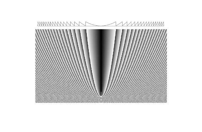
Suppose that we wish to bring parallel incoming radiation to a focus by scattering from elements within an optical system (‘scattering’ should here be thought of as generation of a Huygen’s wavelet; one could equally write ‘reflection’ or ‘diffraction’). Figure 1 shows the phase change necessary as a function of the position of the scattering element in the case of plane incoming wavefronts (source at infinity).
a)

b)

c)

d)

Often each scattering takes place with the same phase change (diffraction by identical atoms, reflection from surfaces …). In this case the scatterers need to be distributed on iso-phase contours, which form a system of nested paraboloids. Figure 2 illustrates how grazing incidence mirrors, multilayer optics, and Laue diffraction ‘lenses’ use respectively reflecting surfaces, alternating layers, and planes of atoms to aim to populate parts of iso-phase surfaces.
In each case only an approximation to the ideal is achieved. For Laue lenses, the planes of atoms are flat and equispaced and so cannot perfectly follow the surfaces. In this case, and for grazing incidence or multilayer optic, practical tolerances are such that the scattering is coherent only very small regions. Lack of coherence means that on larger scales intensities are added, not amplitudes.
1.1 Changing the phase of a gamma-wave
The requirements for focussing can be met exactly if the phase of the gamma-wave can be controlled. Figure 2(d) indicates how the phase change needs to vary across the surface of a planar focussing component in order to concentrate plane incoming wave onto a point. How does one change the phase of a gamma-wave? It turns out to be surprisingly easy Paper1 .
It is well known that grazing incidence reflection relies on the fact that for X-rays and gamma-rays refractive indices are slightly less than unity. Conventionally one writes , where is small and positive. Thus the phase of X/-ray radiation will be changed by any material that it passes through. It is useful to define , which is the thickness of material which leads to a phase change of with respect to the phase in vacuo. This is of course the largest phase change ever needed. Table 1 gives an indication of orders of magnitude of for some example materials and photon energies, as well as of the transmission losses associated with this amount of material. Over a wide range of materials and energies, dimensions are convenient for manufacture and losses are very low.
| 5 keV | 100 keV | 500 keV | ||||||
|---|---|---|---|---|---|---|---|---|
| Material | Absorption | Absorption | Absorption | |||||
| m | % | m | % | % | ||||
| Polycarbonate | 23 | 6.3 | 470 | 0.9 | 2.4 | 2.6 | ||
| Silicon | 13 | 51 | 260 | 0.9 | 1.3 | 2.7 | ||
| Gold | 2.1 | 93 | 39 | 32 | 0.19 | 5.2 | ||
1.2 An example Phase Fresnel Lens for gamma-rays
A consequence of the possibility of modulating the phase of a gamma-wave with a convenient thickness of material is that one can make a lens for focussing gamma-rays simply by giving a disk of material a thickness profile with the form shown in Figure 2(d). This is essentially a Fresnel lens, but as the term is often applied to a simple lens whose thickness is stepped without consideration to maintaining phase, we term it a Phase Fresnel Lens, or PFL.
As an example, such a lens for 500 keV gamma-rays might consist of a 5 m diameter disk of (say) aluminium with a thickness varying between mm (to provide a substrate) and mm. The absorption losses would be 1.6%. We shall consider below the example of such a lens in which the finest pitch of the pattern (at the periphery) is 1 mm.
2 Advantages of Phase Fresnel Lenses
Phase Fresnel Lenses seem to offer major advantages for gamma-ray astronomy.
Angular resolution:
The diffraction-limited angular resolution of a PFL of diameter at wavelength is given by the usual formula for a circular aperture, . In appropriate circumstances there is no reason why resolution close to this limit should not be achieved. For a 5 m diameter lens at 500 keV the diffraction limit is 0.12 micro seconds of arc (as). Sub micro arc second resolution is exactly what is needed to image the space-time around a black hole - a specific objective of NASA’s ‘Beyond Einstein’ program.
Simple manufacture:
Because the refractive index is very close to unity, the manufacturing tolerances necessary in the construction of a PFL are often relatively lax. For an aluminium lens working at 500 keV, optical precision requires only 30 micron accuracy. In such circumstances Gamma-ray lens ‘polishing’ can be done with regular machine-shop tools!
Collecting area:
Because of the low transmission losses and the large geometrical collecting area possible with PFLs, the effective area of a PFL-based telescope can be enormous. Even allowing for absorption, for reasonable detector efficiency (50%), and for rms wavefront errors corresponding to , the effective area of the example 5 m diameter lens would be 65000 cm2.
Low aberrations and non-critical alignment:
With the typical dimensions which are being considered here, a PFL is an extreme example of a high aperture-ratio (-number), thin lens. Consequently geometrical aberrations are low (in fact entirely negligible for any conceivable size focal plane detector) and any tilt of the lens with respect to the viewing direction has little effect (tilts of can be tolerated). In addition the depth of field is relatively large.
| Pitch | Energy (keV) | Aspect ratio | Focal length | Notes |
|---|---|---|---|---|
| 0.5 nm | 100 | 100 m | Typical atomic spacing | |
| 0.5 nm | 1000 | 1 km | ” ” ” | |
| 200 nm | 5 | 16 | 2 km | Note 1 |
| 25 microns | 100 | 2.5 | 5000 km | Note 2 |
| 1.0 mm | 500 | 0.32 | 106 km | Example used here |
Note 1 Same pitch as the Chandra HEG grating
heg
Note 2 Same aspect ratio as the Chandra HEG Diffraction
grating

3 The downside
For a given lens diameter and the focal length of a Fresnel lens is given by . Table 2 gives some example values for a m diameter lens. It can be seen that unless one reduces to the atomic scale (as in Laue lenses), to the nanometric scale (as in multilayer mirrors), or at least to that entailing micromachining, then focal lengths are very long, particularly for high energies.
Minimising the focal length of a PFL by adopting very small is difficult because the necessary thickness (depth) of the structure remains that discussed in Section 1.1 and the ‘aspect ratio’ (pitch/depth) of the required profile becomes very high. Also, although it was argued in Section 2 that tolerances on the thickness are easily achieved, radial tolerances need to be if diffraction limited focussing if not to be compromised.
However, there are reasons for not trying to minimise . The diffraction limited resolution will not be obtained if the detector does not have adequate spatial resolution or if chromatic aberration is too important. Combining the above expression for the focal length in terms of with shows that the physical dimension of the diffraction spot is simply , independent of . A detector with spatial resolution which is of this order of magnitude or worse will cause blurring on an angular scale . Thus any PFL system with , or equivalently , will be limited by detector resolution, not by diffraction. In the case of chromatic abberation, a spectral band of width leads to a blurring . Thus both detector resolution problems and those of chromatic aberration ease with increasing .
Figure 3 shows the effect on the contributions to the angular resolution of changing the design focal length of an example Fresnel lens having m and working at 500 keV. For the baseline design it is supposed that the detector resolution is limited by the track length of the electron receiving the energy of the incoming to mm. Similarly, the spectral band is assumed to be no narrower than the typical resolution of a Germanium detector, keV at 500 keV. It can be seen that unless km, then chromatic abberation will limit the angular resolution to no better than about one as.
Thus the two main problems which need to be addressed are chromatic aberration and long focal length.
3.1 Chromatic aberration
The problems caused by chromatic aberration include both the loss of angular resolution due to blurring of the image and the decrease in sensitivity to which this blurring leads through the necessity of collecting the signal from a larger, and hence higher background, region of the detector. We have seen that the former effect is mimimised by using long focal lengths. The latter bears some discussion.
Suppose one accepts that chromatic abberation is inevitable. Obviously for mono-energetic radiation there is not a problem. For broadband emission, one will properly focus only the radiation in a small fraction of the spectrum. With an energy resolving detector, radiation outside a band can be ignored. One can then pose the question - how wide should be for the best sensitivity? Suppose the sensitivity is limited by noise on the detector background in a focal spot of diameter . We may take the detector background to be proportional to . If is dictated by chromatic aberration then it will be proportional to . For a continuum source, so will the signal . Consequently, assuming that the dominant source of noise is statistical background fluctuations, the signal-to-noise ratio is proportional to . One thus reaches the counter-intuitive conclusion that, in these circumstances, the best signal-to-noise ratio is obtained by using a band as narrow as the detector energy resolution will allow. This is of course also best for angular resolution.
Using a narrow energy band, the sensitivity to a broadband signal will of course not be as good as if a wider bandpass had been possible without compromising the focusing, but given the large collecting area and the tiny background in a small focal spot and in a narrow energy range, it can be amazingly good. The narrow line sensitivity of our example 5 m, 500 keV lens could be photons cm-2 s-1.
Of course, with an energy resolving detector one can use data from energies on either side of the design energy of a PFL, but in general away from the optimum energy the sensitivity and angular resolution are not so supremely good. Diffraction limited focussing does occur also at harmonics of , but the efficiency is low (ignoring differences in absorption, the response at is 4.5% of that at ).
In many circumstances it may be desirable to accept a lower sensitivity in order to gain information at other energies. The available surface area can then be divided into zones tuned to different energies, as is often proposed for Laue lenses. The zoning of the surface can be radial, azimuthal, or into separate lenses with independent focal spots. For many configurations the result will be that a broadband spectrum will be sampled at a limited number of relatively narrow bands – a situation which often has to be accepted in radio astronomy.
Another possibility is to take advantage of the fact that a PFL works over a broad band of energies provided the instrument is refocused by moving the detector to the appropriate focal plane. Figure 4 shows that the obtainable in this way is 1. The time available for each measure will of course be shorter, so in this case too the sensitivity at each energy will be poorer.

Achromatic modifications of PFLs have been proposed (see skinner_achrom and references therein). These rely on combinations of diffractive and refractive components. In practical cases the refractive component has to be stepped to avoid excessive absorption. Such systems hold considerable promise, though because of the stepping the best performance is obtained only for a comb of energies and absorption losses tend to be significant.
It is worth noting that Laue lenses are just as subject to chromatic aberration as PFLs. Over a wide energy band, radiation falling on part of a PFL will be diffracted, though not in the ideal direction. This is directly analogous to Laue diffraction by a mosaic crystal - where again all energies within a certain band are diffracted but with some dispersion in the diffracted direction. Assuming small angles, in each case one finds . The differences are (i) crystal pass bands much narrower and (ii) Laue lenses have imaging properties which are much poorer. Consequently the chromaticity is often insignificant compared with other limitations. Interestingly, if the crystals could be composed of crystallites (or laminae) with the same orientation but having different crystal plane spacing it could be avoided. Such a system would be analogous to a graded spacing multilayer mirror but in Laue geometry in place of Bragg.
3.2 The focal length
It has been argued above that to get the best performance, long focal lengths are inevitable. Given that formation flying technology is necessary for any focal length above 10–20 m, what are the constraints?
First it is worth noting that the idea of formation flying satellites with a scale of 106km is not unprecedented. The joint ESA-NASA Lisa gravitational wave mission will involve 3 spacecraft in a triangular formation with km between each pair. The major difference between the formation flying needed for LISA and that for a for gamma-ray PFL mission is that the LISA formation rotates with respect to inertial space in such a way that each spacecraft follows the local gravity field.
Suppose that we have a one spacecraft with a PFL and another carrying the corresponding detector. If the vector positions of the spacecraft are and , the direction of the separation vector is the pointing direction of the instrument. For it to be constant we must have . If the first spacecraft is in a free orbit then its acceleration is provided by the gravitational field at . In general the gravitational field at will be different and so cannot correspond to the acceleration . To overcome the gravity gradient a station-keeping force must be supplied to one of the spacecraft by a constantly firing thruster.
Gravity gradients close to the earth are too large for a long focal length configuration to be feasible . However a study by the NASA IMDC imdc has shown that for a solar orbit, drifting away from the earth, the thrusts necessary are within the range of available ion engines and that the fuel requirements, although large, are not prohibitive. Other aspects of such a mission were found to present no overriding problems.
The IMDC study set out only to establish feasibility and the orbit selected is not necessarily optimal. It may be that there that there are advantages in having one of the spacecraft relatively close to the earth-moon system, whose gravitational field could, with judicious planning, be used to minimise fuel requirements.
To repoint a million km long telescope at a new target will inevitably take an appreciable time. The IMDC study considered observations of several weeks, with a significant part of the mission time, and the majority of the fuel, used for target changing. It was noted that the efficiency and fuel requirements could be much improved with two detector (or two lens) spacecraft.
3.3 Other considerations: Field of view and target finding
The field of view (fov) over which a gamma-ray PFL yields good imaging can be very large and geometric aberrations are never important. In practice the fov will be limited by detector size. Both pointing accuracy and knowledge of target positions must be good enough to ensure that the target image falls within the the part of the image plane recorded by the detector. With a focal length of 106km, a 1 m detector gives a fov of only 200 as. For comparison, the FGS points HST to an accuracy of 10 milli arc seconds (m.a.s.), 50 times worse .
Existing astrometrical measurements do not provide target locations of the necessary precision. The Hipparchos catalog achieved 1 m.a.s.accuracy, though uncertainties in proper motion mean that it is no longer valid at this level. Successor missions DIVA and FAME will offer improvements for relatively bright stars. Other projected optical astrometry projects are expected to offer major progress in timescales shorter than any likely launch of a gamma-ray PFL mission. ESA’s Gaia (scheduled to be launched in 2010) will measure 300000 stars to 4 as. Although further into the future and less certain, NASA’s OBSS and SIM PlanetQuest missions plans to push the precision down to close to 1 as.
Optical astrometry relies heavily on centroiding and care is necessary with AGN, in which the nucleus is generally embedded in surrounding emission. Radio measurements provide a surer means of astrometry for AGN and offer precisions which are as good as, and currently better than, those possible in other bands. At present the International Celestial Reference system is primarily realised by the International Celestial Reference Frame of 212 extragalactic radio sources with rms position uncertainties of 100 to 500 as.
As well as knowing the location of the source, the vector above, defining the separation and the orientation of the axis of the axis defined by the two spacecraft must be measured and controlled. The problem has been studied in the context of the MAXIM mission, leading to proposals of solutions involving ’super star trackers’ and/or super-conducting gyros gendreau . Given the very long focal length required for a PFL, GPS-like surveying using radio delay/phase measurements to perform can provide information on the positions of the spacecraft in 3-d space and hence constraints on the vector , valuable in obtaining an attitude. A baseline limited by the size of the earth would probably not be adequate, so beacons or transponders on several further spacecraft would be desirable. The reference spacecraft need not necessarily be dedicated to the PFL mission – beacons on multiple, well distributed, spacecraft such as those of the LISA mission would be particularly valuable111It is interesting to note that if a total of at least stations is involved, measurement of the distances and velocities between all pairs formally provides enough information to solve for the coordinates locating them all in momentum space, using no reference other than the structure of the gravitation potential of the solar system. The formation itself becomes an inertial sensor!.
Conclusions
With their extremely good imaging properties, with the exceptionally large effective area possible from a simple device and with the very low background associated with their compact focus, PFLs would probably be the universal means of focussing gamma-rays were it not for the disadvantages discussed above.
It has been argued above that in appropriate circumstances these disadvantages can all be overcome and that although an ambitious mission would be needed, there are no ‘show-stoppers’. Particularly where the ultimate in angular resolution or in point source sensitivity in a relatively narrow energy band is required, PFLs hold enormous potential in the era of gamma-wave astronomy.
References
- (1) Skinner, G.K. “ Diffractive/refractive optics for high energy astronomy -I : Gamma-ray Fresnel Lenses ” A&A 375, 691 (2001), “-II : Variations on the theme” A&A 383, 352 (2002)
- (2) Canizares, C. R., et al. “The Chandra High-Energy Transmission Grating”, PASP, 117 836 (2005)
- (3) Skinner, G.K. “ Design and imaging performance of achromatic diffractive-refractive x-ray and gamma-ray lenses ” Appl. Optics, 43, 4845 (2004)
- (4) Gendreau, K. C., et al. “Requirements and options for a stable inertial reference frame for a 100-micro-arcsecond imaging telescope” Proc SPIE 4852, 685 (2002)
- (5) Phillips, J.D., et al. “Metrology and pointing for astronomical interferometers” Proc SPIE 5491, 320 (2004)
- (6) Krizmanic, J., et al. “Formation flying for a Fresnel lens observatory mission” This volume.