Further author information: (Send correspondence to M. Krumpe)
M. Krumpe: E-mail: mkrumpe@aip.de, Telephone: +49 331 7499 328
published in: Journal: Photonics for Space Environments X. Edited by Taylor,
Edward W. Proceedings of the SPIE, Volume 58981J, (2005).
(c) 2005: SPIE–The International Society for Optical Engineering
X-RED: A Satellite Mission Concept To Detect
Early Universe Gamma Ray Bursts
Abstract
Gamma ray bursts (GRBs) are the most energetic eruptions known in the Universe. Instruments such as Compton-GRO/BATSE and the GRB monitor on BeppoSAX have detected more than 2700 GRBs and, although observational confirmation is still required, it is now generally accepted that many of these bursts are associated with the collapse of rapidly spinning massive stars to form black holes. Consequently, since first generation stars are expected to be very massive, GRBs are likely to have occurred in significant numbers at early epochs. X-red is a space mission concept designed to detect these extremely high redshifted GRBs, in order to probe the nature of the first generation of stars and hence the time of reionisation of the early Universe. We demonstrate that the gamma and x-ray luminosities of typical GRBs render them detectable up to extremely high redshifts (), but that current missions such as HETE2 and SWIFT operate outside the observational range for detection of high redshift GRB afterglows. Therefore, to redress this, we present a complete mission design from the science case to the mission architecture and payload, the latter comprising three instruments, namely wide field x-ray cameras to detect high redshift gamma-rays, an x-ray focussing telescope to determine accurate coordinates and extract spectra, and an infrared spectrograph to observe the high redshift optical afterglow. The mission is expected to detect and identify for the first time GRBs with , thereby providing constraints on properties of the first generation of stars and the history of the early Universe.
keywords:
GRB, first generation stars, space mission, Pop III1 INTRODUCTION
Before the launch of BeppoSAX in 1996, Gamma Ray Bursts (GRBs) were known only as explosive sources of gamma photons, without an identified counterpart in any other part of the spectrum. Subsequently, progress included the explanation of both temporal and spectral variations of the afterglow. However, although thousands of GRBs have now been discovered and observed, a large fraction remain unobserved at other wavelengths. The paucity of observations, poor positional accuracy and low photon fluxes have been important limiting factors.
BATSE-observations of more than 1 500 GRBs revealed two classes according to duration [1]. GRB progenitor theory predicts that the class with the longest duration ( 20 to 100 s) is due to the collapse of massive stars [2], [3], and are detectable up to very large redshifts. For this class, Galama et al. (1998) [4] provides strong evidence for a physical relation between GRBs and supernovae, which can be further classed as faint, low energy supernovae or bright, energetic ones [5]. The latter, so called hypernovae, are associated with the death of fast rotating, massive stars [6]. Consequently, since early generations of stars are expected to be very massive and fast rotators [7], [8], [9],[10], [11], GRBs are likely to have occurred in significant numbers at early epochs. Therefore, they are being increasingly recognized as potentially powerful probes of the very high redshift Universe [12].
Although several space missions have been launched to study GRBs (e.g. HETE2, INTEGRAL and SWIFT), extremely high redshift GRBs are likely to remain undetected/unidentified because their afterglow signatures are outside the observational range of current space missions. Only GRBs up to redshifts of z6 can be observed by their optical instruments. However, luminosities of typical bursts render them detectable even as far as z 10 to 30 [13]. For this reason, we propose a space mission, X-red, dedicated specifically to finding early Universe GRBs. Such bursts (z 10 to 30) will be redshifted into the x-ray region, with optical afterglows redshifted into the infrared region. This work is based on a preliminary mission study conducted by these authors at the ESA summer school on the “Birth, Life, and Death of Stars” at Alpbach, Austria, in 2004. X-red is designed as an ESA project, to be launch between 2012 and 2020, and is planned as a 3 year mission, with the possibility of extension up to 10 years.
2 Observable Science Data
In the following, we examine the feasibility of detecting high redshift GRBs in terms of both statistical number of detections and also adequate flux levels at x-ray and infrared wavelengths. The results dictate the demands on instrumentation described in Section 3. Observations described in the literature of the Universe at redshifts (z 0 to 5) allowed us to use three important assumptions: GRBs are produced by hypernovae, GRBs have the same properties in the early Universe as they do today; and finally, flux extrapolation is possible to high redshifts. However, we are aware that there are several theories about the early Universe (z 5 to 30) that predict even higher GRB frequencies and fluxes. Therefore, it should be noted that our assumptions constitute a worst case scenario.
We can gauge the expected number of detectable GRBs from the detection rate of SWIFT [14] combined with our chosen instrument field of view (FOV) and sensitivity, Section 3.1. The detection rate of X-red is therefore estimated from Fig. 3 of Hartmann et al. (2004) [15], given the higher sensitivity of X-red compared to SWIFT. The total number is expected to be on the order of 800 detections over the 3 year mission lifetime. Of these detections, around 10 % are expected to be from GRBs at z 5 (i.e. at least 80 GRBs at a distance beyond which GRBs have not yet been observed) while 2 % (i.e. 15 detections) are expected to be from GRBs at z 10.
For high redshifted GRBs (z 10) the peak energy output of 100 keV to 600 keV is shifted into the x-ray regime. The observed luminosities span a few orders of magnitude, but tend to higher values at higher redshifts [16]. At z 10, the expected luminosities are a few times 1053-1054 erg cm2 s-1. The expected photon number at a given energy in the GRB spectrum by Meegan (1998) [17] was integrated over the appropriate energy range. Additionally, due to the time dilatation, the GRB is extended to z+1, and so a burst that lasts for 10 s will be observable for 100 s. This provides the time constraint within which the spacecraft must point its follow-up instruments. Unfortunately, however, the time dilatation also causes a decrease in the flux rate of high redshifted GRBs. Figure 1, left panel, takes that into account and shows the calculated flux distribution assuming a luminosity of 1054 erg cm2 s-1.
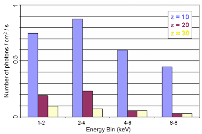

Although the number of photons increases at lower energy bins, so too does the diffuse x-ray background. Therefore, the FOV must be limited in order to detect the GRB above the background. The x-ray afterglow is one to two orders of magnitude lower than the actual burst [18]. Therefore, a focussing x-ray telescope is needed to study x-ray afterglows, or even late x-ray bursts, taking place several minutes after the prompt emission [19]. X-ray focusing telescopes work in an energy range of 0.1-12 keV. Therefore, a possible absorption due to photo-ionization, which is highest at low energies and drops with the third power of energy, is now investigated. In X-red’s observation field, near the galactic poles, the hydrogen number density is NH = 1020cm-2 [20]. According to Wilms et al. (2000) [21] the absorption at 0.1 keV is 4 % and decreases fast with energy. Thus, absorption is negligible.
In the infrared wavelength range, the dimming of the afterglow, redshifting, and time dilatation nearly cancel one another out [13]. The extinction at high redshifts is likely to be small because of the rapid decrease in metallicity beyond z3. Figure 1, right panel, shows the time dependant decrease of afterglow flux. It can be extrapolated to a short time after the burst (Table 1) and specifies the demands on the infrared telescope.
| Time after burst | K-band Flux |
|---|---|
| (s) | (Jy) |
| 10 | 2.5 |
| 60 | 0.15 |
| 180 | 0.026 |
| 360 | 0.0086 |
3 Instrumentation
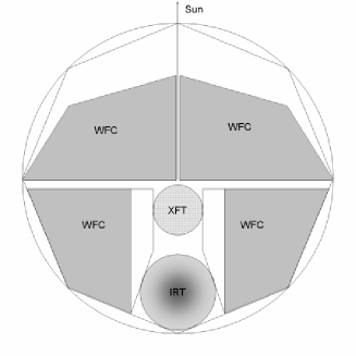
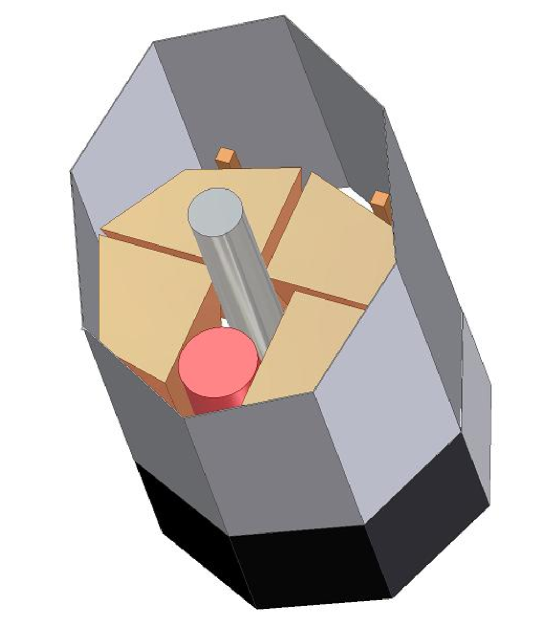
The main objective of X-red is to detect a reasonable number of high-redshifted GRBs with a high positional accuracy. To achieve this objective, the satellite will be equipt with three types of instrument (see layout in Figure 2, left panel). Four Wide Field Cameras (WFCs) operating at x-ray wavelengths will detect high redshift gamma-rays and obtain rough coordinates. The X-ray Focussing Telescope (XFT) will perform imaging observations to improve coordinate accuracy, and will also extract x-ray spectra from which redshifts may be determined. The InfraRed Telescope (IRT) will extract near infrared spectra of the high redshift afterglow.
3.1 Wide Field X-ray Cameras
WFCs operating at x-ray wavelengths will detect high redshift gamma-rays and obtain rough coordinates. The only instruments currently available for observing a large FOV in the x-ray region are coded mask detectors. Each WFC consists of a coded mask placed 1.67 m above the detector plane by a rigid composite structure. The coded masks, e.g. [22] of mm (LWH) lead pieces, were designed to cover the whole available surface of the service module. The dimensions of the satellite structure and the sun shield put engineering constraints on the design and placement of the WFCs. For this reason, there are two pairs of masks (see Figure 2, left panel). The two masks closer to the Sun are symmetric, have a maximum size of m and have almost 160 000 elements each (with % of them transparent to x-rays). The two masks on the further side from the Sun, also symmetric, have a maximum size of m and over 161 000 elements each.
The two main problems posed by detectors covered by coded masks are the background photon noise level and the lack of collimation in photons reaching the detector itself. Since X-red requires not only a large FOV but high sensitivity (see Section 2), these difficulties must be overcome. To overcome the background photon noise, a combination of four WFCs is used, with each WFC surrounded by a shield. More importantly, it is now possible to avail of the Depleted Field Effect Transistor (DEPFET) detector technology, a new CCD technology with hybrid soft and hard x-ray detection and high speed individual pixel readout, currently in development for the XEUS mission. This technology allows considerable improvement in background noise reduction, see below. (The lack of flux collimation is addressed by the XFT design, Section 3.2.)
Each WFC is equipped with two 7070 cm detectors, covering an energy range between 0.1 keV and 100 keV. A 7070 cm Depleted Field Effect Transistor (DEPFET) is placed in front of a 7070 cm cadmium telluride (CdTe) detector, such that hard and soft x-ray detection is possible (see [23] for a complete explanation of DEPFET and CdTe detectors). The two detectors can be used to trace the photon’s path. By knowing the detection position in both detectors, it is possible to eliminate background photons. Hence, the background photon noise can be reduced even further.
| Soft x-ray detector | Hard x-ray detector | |
| Size | 7070 cm2 | 7070 cm2 |
| Number of elements | 700700 | 700700 |
| Size of each element | 11 mm2 | 11 mm2 |
| Spectral range | 0.1 - 10 keV | 10 - 100 keV |
| Power consumption | 20 W | 25 W |
| Total WFCs Mass | 4 x 40 kg | |
High redshifted GRBs () are fainter than medium redshifted GRBs (). Coded mask instrument sensitivity increases with the size of the detectors. According to the expected fluxes, all detectors have been designed large enough to be able to detect a typical GRB at within their energy range. The large detector dimensions and the number and size of the pixels (see Table 2) may be considered ambitious. However, it is expected that technological advances are likely to meet this demand by the planned launch date of X-red.
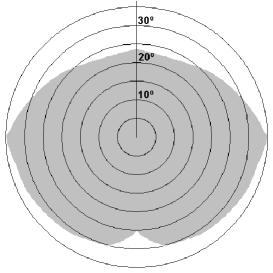
Overall, with this configuration, the total FOV of the four WFCs (which have coded masks of 50 % transparency) is 0.6 steradians (, Figure 2, right panel), and the positional accuracy is 1 arcmin (FWHM 6 arcmin), as determined by the mask-to-detector distance, the size of the mask elements and the detector pixels.
3.2 X-Ray Focussing Telescope
The second x-ray instrument on-board is the XFT, which will perform imaging observations to improve coordinate accuracy, and will also extract x-ray spectra from which redshifts may be determined. With this instrument, we can overcome the second difficulty posed by the WFC coded mask (mentioned in Section 3.1), i.e. the lack of collimation in photons reaching the detector.
X-ray grazing incidence mirrors are able to focus x-rays but only under very small reflection angles and, with increasing photon energy, the angle becomes even smaller. This results in the typically large focal lengths of x-ray telescopes. Meanwhile, the dimensions of the fairing (Section 4.4) and moment of inertia considerations (Section 4.3) impose a limit on the available focal length for the XFT of 5.5 m, with corresponding radius 0.28 m (scaling a XMM-Newton type telescope). We must look to new technologies to ensure adequate sensitivity under these focal length and radius restrictions.
Silicon High-Precision Pore Optics (Si-HPO, or simply ‘pore optics’) is another challenging new technology currently in development for the XEUS mission (as is DEPFET, Section 3.1). Although the constraint on maximum tolerable graze angle for pore optics is the same as for conventional mirrors, pore optics can be made to more efficiently fill the aperture of the telescope. This means it is possible to obtain a given effective mirror area with a telescope of smaller opening. This in turn translates to a shorter focal length. So the use of pore optics will not only have the effect of drastically decreasing the mass of the mirrors since it is very light-weight, but will increase the effective area substantially. With our chosen design, a pore optics telescope will have an effective area of 1 400 cm2 @ 1.5 keV, which is 12 times better than SWIFT [24], [25].
Having collimated the photons, we then choose to implement a photon counting intrinsic energy resolution detector. As with the WFCs, we use DEPFET detector technology of with pixel. The detector will be read out every 1 ms in window mode (i.e. only partial detector read-out according to GRB location, resulting in increased speed and hence allowing photon energy resolution). The observational data will yield both x-ray images and spectra. Given a FOV of 10 arcmin a GRB position accuracy of 1 arcsec is feasible. Further technical details are listed in Table 3. From the x-ray spectrum, we can identify emission and/or absorption lines which allow determination of the redshift.
| Telescope | Detector | |
| Type | Si-HPO | DEPFET |
| Dimensions | r = 28 cm | 3.2 cm 3.2 cm |
| F = 5.5 m | 640 640 pixel with 50m 50m | |
| Mass | 50 kg | 40 kg |
| Resolution | mirror 5" GRB position: 1" | |
| Energy range | keV | |
| 150 eV FWHM | ||
| Effective Area | @ | |
| Field of View | 10 arcmin | |
3.3 Infrared Telescope
The IRT is intended to extract spectra of the high redshift optical afterglow. The demands on the IRT are dictated by the nature of high redshifted afterglows of GRBs. These events are limited in lifetime (days to months) and the flux is continuously decreasing rapidly, so it is crutial to obtain a spectrum as soon as possible.
In the majority of GRB afterglows, Lyman- is the most distinctive absorption line [26] and is detectable even with low-resolution spectroscopy and in a noisy spectra. Even though other emission and/or absorption lines are recognized in afterglows, we expect Lyman- to be the most prominent line from the first generation of stars, due to their chemical composition. At a redshift of 5 to 15 or even up to z20, Lyman- is shifted into the near infrared ( 0.73 to 1.95 m, or even 2.55 m). However, for clear determination of the redshift, detection of other features is also desirable. Hence, the detector’s wavelength range should exceed m. For an adequate signal-to-noise ratio, our choice of detector must operate at 35 K. The corresponding demand on thermal design puts strong constraints on the telescope, the detector and the whole spacecraft. Active cooling systems have the disadvantage that they limit the lifetime of the mission significantly and increase the spacecraft’s mass substantially. Passive cooling to 35 K is an engineering challenge but it is absolutely desired, and possible if the complete satellite architecture is designed according to this requirement (Section 4.4.2).
Considering the required spectral range and the feasibility of passive cooling, the Near Infrared Spectrograph (NIRSpec) of the James Webb Space Telescope can serve as a basis for the detector design [27]. This operates in the wavelength range of 0.6 to 5.0 m and offers a range of resolutions (R = 100 - 3 000). Given that afterglow fluxes decrease rapidly over time, high resolution spectroscopy is not possible since the photon rates are low and space-based mirrors are too small. However, for determination of redshift, low resolution spectroscopy is sufficient. Therefore, we propose a modified NIRSpec with a "low" resolution mode of R 30 and a "high" resolution mode of R 100. For a telescope diameter of 0.85 m the required minimum near infrared fluxes for a 10 event corresponds to 8.6 (or 28.5) mJy (by scaling NIRSpec) at a given resolution of R 30 (or R 100).
| IR-Telescope | IR-Detector | |
| Diameter | 0.85 m | 0.80 m |
| Height | 1.5 m | |
| Operating temperature | 50 K | 35 K |
| Mass | 50 kg | 100 kg |
| Spectral range | 0.6 - 5 m | |
| Resolution | R 30, R 100 | |
| Field of View | 3.4 3.4 arcmin | |
| Power consumption | 20 W | |
4 Mission Architecture
4.1 Orbit & Launcher
The spacecraft orbit was chosen as the Lagrangian point, L2, where gravitational pull and centripetal force between Sun and Earth are equal. This location will provide long term uninterrupted observations of GRBs and their afterglows with the XFT and IRT, which would not be achieveable from an Earth orbit. The location will also avoid eclipses, giving a stable thermal environment.
Thanks to the advanced light-weight instrument technology (Section 3) and choice of light-weight passive cooling (Section 4.4), the mass loading is minimised and so we can choose the cheaper Soyuz launcher, which imposes a lower mass constraint than the more expensive Ariane 5. This choice also, however, gives some limiting constraints to the total dimensions of the spacecraft. It will be equipt with the new ST fairing (offering larger dimensions for a bigger payload). The internal dimensions of this fairing are 3.8 m in diameter and 9.5 m in height, but forming a cone at the top which leaves an effective height Heff 6 m for the basic 3.6 m diameter cylindrical shape. A Fregat module, which provides the final injection to L2, is included in the fairing.
It is expected that the Soyuz–Fregat spacecraft will be launched from the European Spaceport in Korou. The Soyuz will bring the spacecraft to an intermediate orbit around Earth at which point the Fregat module then performs the injection to the transfer orbit, including a fly-by maneuver with the moon, until it finally reaches L2. Upon arrival, the spacecraft will perform a halo–orbit about the instable L2 point, with a total amplitude of m.
4.2 Propulsion
In order to correct the flight trajectory to L2, and to maintain stability about the instable L2 point, a propulsion system will be included in the spacecraft. Additionally, this will serve to offload the momentum wheels (Section 4.3), which are included in the spacecraft for pointing manoeuvres. Required trajectory corrections of 50 m s-1 and stability corrections of 2 m s-1 yr-1 are expected. Estimating an extended maximum lifetime of 10 years for the mission, the sum of all corrections is 70 m s-1.
The thruster propellant chosen is hydrazine (N2H4), for its high specific impulse (Isp 230 s) compared to a liquid gas like nitrogen (Isp 70 s). Electrical thrusters (Isp 1 000 s) do exist but they require a stable high voltage supply and a non-standard power processing unit, the mass of which increases with specific impulse. Also, they offer best performance for long thrust periods, and so are not required for this mission. Furthermore, structure and mass constraints preclude electrical thrusters. Therefore, hydrazine thrusters are favoured, as their high specfic impulse means lower fuel mass rendering them more suitable for longer duration missions. In addition to the propellant mass, the specifications for the thrusters, pipes and valves have to be considered. For the expected requirements, a system of 16 thrusters each providing a force of 10 N is deemed sufficient. The propellant will be stored in two tanks situated in the service module. The mass estimated for a total lifetime of 10 years is 70 kg, and is broken down as follows: propellant 50 kg; tanks (26 kg) 12 kg; thrusters (160.3 kg) 4.8 kg; pipes and valves 3 kg.
4.3 Attitude Control
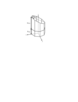
Since using thrusters for the attitude control would add extra propellant mass and exceed the mass limitations of the spacecraft, we choose instead a four momentum wheel system (for redundancy purposes) orientied in a tetrahedron to control the rotation of the spacecraft. This attitude control system will include two star trackers, with a positional accuracy of 0.25 arcsec (FWHM1.0 arcsec), pointing parallel to the XFT – IRT alignment. The spacecraft is of effective height Heff 6 m (Section 4.1) and of mass m 1 500 kg (Section 5). Assuming a cylindrical geometry, the satellite’s highest possible rotational moment of inertia, , (i.e. about the x or y axis, see Figure 3) was estimated by
where R is the spacecraft radius and Hcom is the height of the center of mass of the cylinder (Hcom= Heff-HSM, see Section 4.4). The first term represents a rotation around the center of the cylinder. The second term is a correction term, using Steiner’s law, to account for the distance offset between the center of the cylinder and its center of mass, since the center of mass is located between the service module (SM) and payload module (PM) (Figure 3, left panel). The resulting moment of inertia is 9 100 kg m2. Since the momentum wheels must slew the satellite to any point in the FOV of the WFCs within 60 seconds, an angular speed of 0.01 rad s-1 must be achieved. Therefore, the momentum wheels are required to store an angular momentum of 91 N m s.
| Angular momentum | 91 Nms |
|---|---|
| Operating speed | 8000 rpm |
| Max. speed | 15000 rpm |
| Weight | 4 x 11 kg = 44 kg |
| Size(diameter, height) | 280 mm x 30 mm |
| Peak power | 750 W |
| Mean power | 100 W |
4.4 Spacecraft Engineering
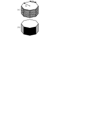
The spacecraft is divided into two parts: the service module (SM) and the payload module (PM) (Figure 3, left panel). The PM carries all the scientific instruments, the communication antenna, star trackers, sun shields and passive cooling radiators. The SM includes all the devices necessary for housekeeping, attitude control, propulsion system, etc. The solar panels are mounted on the side facing the Sun (chequered areas in Figure 3(a). The back side is equipped with black painted radiatiors (Figure 3(b)). Finally, due to its comparatively long focal length, the XFT necessarily extends into the SM.
General considerations in spacecraft engineering include the structure and thermal design. The structure must provide the stiffness necessary to survive the launch, and to assure pointing accuracy during the mission. The thermal design must ensure the instruments are shielded from solar radiation, since they need to be kept at certain operational temperatures. Rather than choosing a cylindrical shape, an octagonal structure for the spacecraft was chosen for ease of design (particularily regarding the solar panels) and cost efficiency. Lastly, the surface of the spacecraft has to be electrically conductive, avoiding potential differences that could cause discharges and damage to the devices on-board.
4.4.1 Power Systems
The major components of the power systems consist of solar arrays, storage batteries, a power regulator system and a power distribution system. In this section we will focus on the main power source, the solar arrays. The orbit for X-red around L2 will avoid eclipses, thus the solar arrays are a reliable source of power. However, storage batteries must be included as well, in order to provide peak power to the spacecraft and also as a backup power source for possible emergency scenarios. To design the solar arrays, the power requirements of the different subsystems were estimated (Table 4).
| Subsystem | Power requirement |
|---|---|
| WFC | 180 W |
| IRT | 20 W |
| XFT | 15 W |
| Momentum wheels | 100 W, (750 W peak) |
| Telecommunication | 100 W |
| Data handling | 20 W |
| Attitude sensors | 20 W |
| Power system itself | additional 20% |
| Total | ca. 550 W |
The power loss from the solar arrays to the loads is expressed by the supply efficiency 0.85, while further degradations (design and assembly inefficiencies, degradations due to non-optimal temperature of the array and inherent degradation) add up to a deployment efficiency 0.55 [28]. To fulfil the power requirements, highly efficient solar arrays are mounted on the SM. A product from Spectrolab was chosen, for illustration. The Ultra Triple Junction (UTJ) Solar Cells have a minimum average efficiency at the beginning of life (BOL) of = 28 % and at the end of life (EOL) = 24.3 %. The solar radiation density (solar constant) at the L2 orbit (i.e. at a distance of 1 AU + 1.5 109 m from the sun) is . The power output from a solar cell at the EOL (worst case) is then controlled by the following relationship:
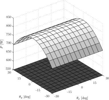
where is the solar zenith angle (i.e. the angle between the normal vector of the area and the solar rays) and is the area of the cells. By simple considerations, the required area amounts to 3.5 m2. However, since our spacecraft is octagonal and our spacecraft is designed to rotate by about the x and/or y axis (implying that sides facing the sun always have different solar zenith angles), a more sophisticated approach is desirable. A simulation program was written to study in detail the impact of rotation on power generation and thermal aspects. As a result of the geometry of the SM, the total area of the solar panels is . Figure 4 illustrates that the chosen area guarantees the required electric power even given EOL and low light conditions.
4.4.2 Thermal design
When faced with a long mission duration and mass limitations, passive cooling becomes imperative. The primary engineering challenge is the cooling of the IRT, which will operate at 35-50 K. The spacecraft will orbit around L2, thus one side will always point towards the Sun and the other always away from it. A black body in space will radiate according to the Stefan Boltzmann fourth power law, and will absorb the incident solar radiation :
where is the emittance, is the absorptance, and is the Stefan-Boltzmann constant equal to [29]. Choosing materials with the right absorptance and emittance properties is crucial. The sum of the absorbed power and dissipated power should not exceed the radiated power. A spacecraft in thermal equilibrium fulfils
where is the solar constant, the absorptance of each face, the area of each face, the temperature of each face and is the solar zenith angle of the faces. Only faces with a solar zenith angle within contribute to the absorbed power.
Thermal design of the PM
The PM consists mainly of the WFCs, the XFT, the IRT, a sunshield and radiators. The 30∘ cut
(Figure 3, i.e. right side is smaller than the left side) is designed to shield the
instruments from solar radiation. The XFT detector plane will reside in the SM, and so must be thermally
controlled there. The IRT has to be kept on the shaded side in order to avoid heat as much as possible, because
of its sensor temperature requirement of 35 K. Thermal insulation has to be optimal, with a maximum
heat transfer, Q, of 1 W. The WFCs, which consume a lot of power, are kept at room temperature.
Table 7 provides an overview of the relevant instrument data.
| Instrument | Power dissipation | Temperature | Heat Transfer | Area required |
| (W) | (K) | (W) | (m2) | |
| WFC | 200 | 293 | 10 | 0.03 |
| IRT | 20 | 35 | 1 | 13.06 |
| XFT | 15 | 253 | 2 | 0.01 |
Parts of the payload structure that are facing the Sun are coated with white paint (e.g. Alion products YB-71 and YB-71P with 0.12 and 0.90), the back side is passively cooled by radiating areas coated with black paint (e.g. Alion products MH216NLO and MH21-IP with 0.95 and 0.90). Therefore, the required area follows from
where is the heat transfer for the th area and the corresponding temperature.
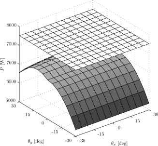
Simulations showed that the required area for the radiators (Table 7) does not exceed the
available area. This is of particular interest since 35 K for the IRT is difficult to achieve by passive
cooling. By using the suggested material the thermal budget yields more radiated power than absorbed power as
can be seen in Figure 5(a) because the white paint covers a rather big area and has a
high emittance. This fact is important because heating is always easier than cooling. By using different
materials (polished aluminium or black paint) or heaters, a more balanced thermal budget is possible. In
our analysis, we neglected detailed structures, such as the high gain communication antenna dish on the front,
which would contribute to heating rather than to cooling.

Thermal design of the SM
The front face of the SM is completely covered by solar panels, which will heat up the module. The thermal
design of the SM focusses mainly on keeping the module at room temperature to guarantee a stable operating
temperature for its devices, particularly the batteries and the propellant. This is done by radiators on the
rear face. Given that there is also an instrument in the SM, the XFT, an additional radiator panel has to be
provided to keep it at the specified temperature (Table 7). Simulations confirmed that,
within rotations of (about the x and/or y axis), the radiated power always exceeds the sum of
the absorbed and dissipated power (Figure 5(b)).
In summary, it is shown that the proposed design is feasible in providing the required thermal specifications of all instruments and devices. The layout allows operation of the IRT in the temperature range of 35-50 K. Calculations reveal the engineering challenge to be insulation of the IRT such that the heat transfer does not exceed 1 W, in which case it will not be possible to allocate sufficient area for the radiators.
4.5 Telemetry
The aim of this section is to estimate the amount of data produced by the various on-board instruments, and to examine the best way to communicate with the ground stations. The largest amount of data will undoubtedly come from the WFCs. This is mainly due to the diffuse x-ray background, the intensity of which is estimated as follows, [30], [31]. The number of photons in a given energy range ( cm-2 steradian-1 s-1) is given by:
Integrating over the appropriate energy range (0.1-100 keV), and multiplying by the total detector area and FOV of the four WFCs, gives a total number of 87 000 photons s-1 (assuming coded mask efficiency 50 %). The relevant data that needs to be stored for every photon consists of six characterising numbers: the (x,y) position on both detectors, the x-ray energy, and the time. Since each of these will be stored on 10 bits, it amounts to 60 bits per photon. So we expect the data rate of the 4 WFCs to be 5.3 Mb s-1, while the XFT and IRT require comparatively negligible rates (i.e. 50 kb s-1). The total comes to 5.5 Mb s-1.
The large data rate leaves two alternative. The preferred scenario involves using a high-gain, steerable antenna (HGA) in searching for GRBs. In addition to the HGA continuously transmitting WFCs data to Earth, a medium-gain antenna (MGA) ensures minimal data transmission for housekeeping and emergency situtations. Also, the spacecraft must be capable of storing data onboard for a limited time. Estimations show the need for a 1.2 m diameter HGA and a ground antenna diameter of 30 m. However, various restrictions have to be considered. Currently, available ground stations cannot ensure complete ground coverage, and a steerable HGA can constrain the observable region. However, the data rate is the main concern, even given data compression. For other space missions, data transmission rates of almost 3 Mb s-1 are under development and will be achievable from L2 when satellite missions like GAIA [32] are launched. The alternative scenario uses a MGA, which inevitably means onboard raw-data processing and storage. The reduced data are transmitted to ground during a limited time interval (typically a few hours). The first scenario is much more attractive, mainly because of the higher flexibility and real-time ground-based data processing, but its feasibility depends on future developments mainly in antenna technology.
5 Mass Estimate
One of the key points to note about this mission design is the light-weight technology and feasibility of passive cooling (which does not increase mass through fluid considerations). This allows us to choose a smaller launcher (Section 4.1), which ultimately leads to a significant reduction in overall mission costs. The individual masses for the subsystems are roughly broken down as follows: WFC160 kg ; XRT 90 kg; IRT 150 kg; attitude control system 114 kg; power system & telemetry 130 kg; structure 550 kg. This gives a total mass of the spacecraft within the mass limitations for a Soyuz launcher, i.e. 1 500 kg.
6 Observing Strategy
Observing the sky for GRBs is the primary objective of the X-red mission. The mission design accounts for the fact that we cannot observe in either the galactic or ecliptic planes, so as to avoid high x-ray background levels and possible x-ray flashes unrelated to GRB events.
While the WFCs are monitoring the sky for GRBs, the WFCs data (with positional accuracy of 1 arcmin) are analyzed by the satellite’s software and are continuously transmitted to Earth in real time. The spacecraft then acts automatically on the coordinate information, to take further data with the other instruments. However, the satellite’s GRB detection software will have a high detecting threshold, to prevent triggering by false events. Ground stations have the option to analyze the WFCs’ data, and may choose to override the satellite controls in order to study GRBs that failed to reach the detection threshold. In this case, the total time loss would be 20 s. Whether by automatic instruction or manual override, the satellite will slew to point the XFT and IRT on the GRB position in less than 60 s. The XFT and IRT instruments will then observe the GRB and its afterglow. The XFT can improve the positional accuracy to within 1 arcsecond, and immediately transmit this information to Earth where ground-based telescopes may choose to begin follow-up observations. Note, however, that thermal and power issues place restrictions on spacecraft orientation and so, following observation of several GRBs, the spacecraft must be reorientated to a position that ensures optimal thermal and power conditions.
7 Conclusions
Extremely high redshifted GRBs provide unique probes of the first generation of stars and the early Universe. We present X-red, a complete mission design from the science case to the payload and overall mission architecture, the objective of which is to observe these high redshift GRBs for the first time.
We have demonstrated the feasibility of detecting high redshift GRBs in terms of both statistical number of detections and also adequate flux levels at x-ray and infrared wavelengths. The results dictated the demands on instrumentation. We then describe the payload which comprises three instruments, namely wide field x-ray cameras to detect high redshift gamma-rays, an x-ray focussing telescope to determine accurate coordinates and extract spectra, and an infrared spectrograph to observe the high redshift optical afterglow. We successfully demonstrate that our scientific objectives are achieveable when harnessing new technologies (i.e. DEPFET and pore optics), and we successfully meet instrument accomodation and environmental demands through our mission architecture. One of the key points to note about our overall mission design is the light-weight technology and feasibility of passive cooling. This significant reduction in mass allows us to choose a smaller launcher, which ultimately leads to a significant reduction in overall mission costs without compromising scientific objectives.
In the planned 3 years mission, we expect to detect and identify 15 GRBs of z10. These will constitute the first observations of high redshift GRBs, and are expected to provide valuable constraints on properties of the first generation of stars and on the history of the early Universe.
7.1 Acknowledgments
We would like to thank all the tutors of the 2004 ESA summer school for their help and suggestions, our dear friend Prof. Dr. Johannes Ortner for a perfectly organized summer school, all professors for their inspiring lectures, the summer school’s staff, ESA and its single national societies (DSRI, DLR, ASA, etc.) for the financial support of the summer school and participants. Without this help, the collaboration for this paper would not have been possible.
Mirko Krumpe is supported by the Deutsches Zentrum für Luft- und Raumfahrt (DLR) GmbH under contract No. FKZ 50 OR 0404.
References
- [1] A. Balastegui, et al., “Reclassification of gamma-ray bursts,” MNRAS 328, pp. 283–290, 2001.
- [2] S. E. Woosley, “Gamma-Ray Bursts from Stellar Collapse to a Black Hole?,” Bulletin of the American Astronomical Society 25, pp. 894–+, 1993.
- [3] T. Matheson, et al., “Photometry and Spectroscopy of GRB 030329 and Its Associated Supernova 2003dh,” ApJ 599, pp. 394–407, 2003.
- [4] T. J. Galama, et al., “An unusual supernova in the error box of the gamma-ray burst of 25 April 1998.,” Nature 395, pp. 670–672, 1998.
- [5] K. Nomoto, et al., “Hypernovae, Black-Hole-Forming Supernovae, and First Stars,” in ASP Conference Series, pp. 384–+, 2005.
- [6] P. Podsiadlowski, et al., “The Rates of Hypernovae and Gamma-Ray Bursts, ” ApJL 607, pp. L17–L20, 2004.
- [7] T. Abel, et al., “The Formation of the First Star in the Universe,” Science 295, pp. 93–98, 2002.
- [8] M. L. Norman, et al., “First Structure Formation and the First Stars,” in The First Stars. Proc. MPA/ESO Workshop held Garching, Germany, 4-6 August 1999. A. Weiss, T.G. Abel, V. Hill (eds.). Springer., pp. 250–+, 2000.
- [9] P. Marigo, et al., “Evolution of zero-metallicity massive stars,” in IAU Symposium No.212, pp. 334–+, 2003.
- [10] P. Marigo, et al., “Zero-metallicity stars. II.,” A& A 399, pp. 617–630, 2003.
- [11] R. Kudritzki, “Line driven winds, ionizing fluxes and UV-spectra of hot stars at extremely low metallicity,” in IAU Symposium No.212, 325–+, 2003.
- [12] A. Loeb, “Cosmological Studies with gamma-Ray Bursts,” LNP Vol. 598: Supernovae and Gamma-Ray Bursters 598, pp. 445–456, 2003.
- [13] D. Q. Lamb and D. E. Reichart, “Gamma-Ray Bursts as a Probe of the Very High Redshift Universe,” ApJ 536, pp. 1–18, 2000.
- [14] J. Gorosabel, et al., “The potential of INTEGRAL for the detection of high redshift GRBs,” A& A 427, pp. 87–93, 2004.
- [15] D. H. Hartmann, et al., “Tracing cosmic star formation with EXIST,” New Ast. Rev. 48, pp. 237–241, 2004.
- [16] D. Yonetoku, et al., “Gamma-ray burst formation rate inferred from the spectral peak energy-peak luminosity relation,” ApJ 609, pp. 935–951, 2004.
- [17] C. A. Meegan, “Gamma-ray burst overview,” Advances in Space Research 22, pp. 1065–1075, 1998.
- [18] J. van Paradijs, et al., “Gamma-Ray Burst Afterglows,” AnnRevA& A 38, pp. 379–425, 2000.
- [19] L. Piro, et al., “Probing the Environment in Gamma-Ray Bursts,” ApJ 623, pp. 314–324, 2005.
- [20] A. A. Stark, et al., “The Bell Laboratories H I survey,” ApJS 79, pp. 77–104, 1992.
- [21] J. Wilms, et al., “On the Absorption of X-Rays in the Interstellar Medium,” ApJ 542, pp. 914–924, 2000.
- [22] D. Vigneau and D. W. Robinson, “Large coded aperture mask for spaceflight hard x-ray images,” in X-Ray and Gamma-Ray Telescopes and Instruments for Astronomy. J. E. Truemper, H. D. Tananbaum (eds.) Proc. SPIE, Vol. 4851., pp. 1326–1335, 2003.
- [23] M. Bavdaz, et al., “XEUS mission reference design,” in Proc. SPIE, Volume 5488., pp. 530–538, 2004.
- [24] M. Bavdaz, et al., “Status of x-ray optics development for the XEUS Mission,” in Proc. SPIE, Vol. 5488., pp. 829–836, 2004.
- [25] M. Beijersbergen, et al., “Silicon pore optics,” in Proc. SPIE, Vol. 5488., pp. 868–874, 2004.
- [26] P. M. Vreeswijk, et al., “The host of GRB 030323 at z=3.372,” A& A 419, pp. 927–940, 2004.
- [27] R. Hofferbert, et al., “Prototyping of cryomechanisms for the JWST near-infrared spectrograph,” in Ground-based Instrumentation for Astronomy. A.F.M. Moorwood; M. Iye (eds.). Proc. SPIE, Vol. 5495., pp. 56–66, 2004.
- [28] J. R. Wertz and J. R. Larson, Space Mission Analysis and Design, Kluwer, third ed., 1999.
- [29] P. Fortescue, et al., Spacecraft Systems Engineering, Wiley, third ed., 2003.
- [30] D. E. Gruber, “The Hard X-Ray Background,” in The X-ray Background, Cambridge University Press, X. Barcons, A.C. Fabian (eds.), pp. 44–+, 1992.
- [31] M. Revnivtsev, et al., “The spectrum of the cosmic X-ray background observed by RTXE/PCA,” A& A 411, pp. 329–334, 2003.
- [32] U. Lammers, “Gaia Telemetry Rate Simulations,” in Proc. Gaia Symposium "The Three-Dimensional Universe with Gaia" (ESA SP-576). Observatoire de Paris-Meudon, 4-7 October 2004. C. Turon; K.S. O’Flaherty; M.A.C. Perryman (eds.), pp. 445–+, 2005.