Absolute calibration of the LOPES antenna system
Abstract
Radio emission in extensive air showers arises from an interaction with the geomagnetic field and is subject of theoretical studies. This radio emission has advantages for the detection of high energy cosmic rays compared to secondary particle or fluorescence measurement methods. Radio antennas like the LOPES30 antenna system are suited to investigate this emission process by detecting the radio pulses. The characteristic observable parameters like electric field strength and pulse length require a calibration which was done with a reference radio source resulting in an amplification factor representing the system behavior in the environment of the KASCADE-Grande experiment. Knowing the amplification factor and the gain of the LOPES antennas LOPES30 is calibrated absolutely for systematic analyses of the radio emission.
1 Introduction
The long known radio emission in extensive cosmic ray air showers (EAS) is again under investigation with new fully digital radio antennas. Nearly 40 years ago, in the early 1960’s this nano-second short weak pulses in EAS were detected and basically confirmed with theoretical predictions. With recent theoretical studies (Huege and Falcke[1]), using a more detailed Monte-Carlo technique, and a new generation of radio telescopes the comparison of predictions and measured radio emission in EAS provides us with a capable method for EAS investigation. The stochastic production process of EAS is a complicated phenomenon. Therefore as many observables as possible are needed to reconstruct the primary shower parameters correctly. The digital radio antenna field of LOPES30 placed inside the existing multiple detector-component experiment KASCADE-Grande[2] is now calibrated absolutely allowing us to measure precisely the long known radio emission in EAS and their dependencies on primary shower parameters like arrival direction, primary particle mass and energy.
2 Radio emission in EAS
Analytical calculations in the early 1970’s[3] of the expected electric field strength , the lateral distribution of and the dependence on the shower direction predict electric field strengths at ground level in the range of – V/m/MHz ( – V/m/MHz) for primary energies eV. The definition of the quantity and a conversion factor for can be found in [4]. On the basis of the so called geosynchroton-effect a new analytical model for the calculation of the electric field strength was developed 2003 by Huege and Falcke. The results of the simulations have been summarized with a parametrisation formula to get expected electric field strength occurring in EAS. From this parametrisation formula one gets electric field strength at ground in the range of – V/m/MHz also for primary energies eV. There has never been a common agreement about the absolute field strength[5] and the values cited decreased over time to a tenth of a V/m/MHz. For the absolute calibration of LOPES30 these values give a first benchmark to our detection thresholds but they do not really represent typical values of electrical field strengths occurring in model prediction of EAS.
3 Calibration setup for LOPES30
With LOPES10 the “proof of principle” in detecting radio emission from EAS was achieved by comparing relative field strengths in the antenna array [6] and comparing them with the parameters obtained by KASCADE-Grande. The analysis was done without a precise absolute calibration and therefore only a qualitative comparison with theoretical predictions was possible. An absolute comparison can be done by knowing the system (Fig. 1) response to a calibrated well defined signal where the knowledge of the voltage amplitude and signal phase is included.

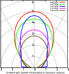
Due to their inverted-V-shape the antennas are most sensitive to vertical EAS and less sensitive to highly inclined signals () except around 60 MHz as shown in figure 2, left. A mechanically needed quadratic ground plate (2.5 x 2.5 m2) of aluminum modifies the antenna gain, i.e. it increases the antenna gain in the range of 60 MHz towards highly inclined signals and decreases the gain for vertical signals. From a commercial reference radio source (VSQ 1000[7]) the electrical field strength in a certain distance is known and the emitted time-continuous and frequency discrete signal is used. This means that the reference radio source emits in 1 MHz, 5 MHz, or 10 MHz steps a defined sine wave, e.g. at 55 MHz around four orders of magnitude higher in power than EAS radio emission, at 10 m distance in the main direction. In our calibration setup the radio source was placed above the top of the LOPES antennas. Mounted at the end of a wooden beam fixed on an extension arm of a crane we determined for each antenna an individual frequency dependent amplification factor. These values represent the overall system behavior to the input signal emitted by the reference antenna and therefore all active and passive components in the electronic system (see figure 1) contribute with their individual gain. It is more difficult to calculate an amplification factor from a single component calibration of the full electronical chain, because some components do not have exactly 50 impedance. For the calibration the transmitted power , the gain of the reference radio source, and the gain of the LOPES antenna correlate with the received power :
| (1) |
In the temporary setup of a merely simulated LOPES antenna gain the received power can be determined. The polarization angle is needed to take into account that the LOPES antennas are linearly polarized and therefore the angle between polarization axes of the emitter and polarization axes of the detecting antenna modifies the received power. For all LOPES antennas we succeeded to measure the received power in the main sensitivity direction.
4 Results
In a campaign of three days the measurements were done in the 5MHz or 1MHz step mode of the reference radio source. The fraction of transmitted power to received power is proportional to an amplification factor calculated from a 9.8 msec dataset for each LOPES antenna. We determined such amplification factors for all antennas which can vary from antenna to antenna by a factor of ten with a typical uncertainty of around 15%. The relatively large factor of ten between the antennas is mostly caused by the characteristics of the bandpass filter and is one of the important contributions to the amplification factor. The uncertainties at 50 MHz are larger compared to frequency ranges above and below because of amateur radio communication occurring in this band. For one antenna we measured the received power in different weather conditions. In figure 2 three curves are shown, representing the amplification factors as a function of frequency, for very dry conditions, wet conditions, and also during rain fall.
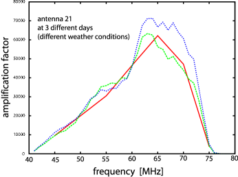
As a first result it is obvious that the conditions during the calibration measurement such as soil humidity, rain fall, or relative humidity influenced the values of the amplification factor. These first results need further detailed investigations. A weather dependent correction factor for the LOPES antenna system can minimize these calibration uncertainties. Furthermore above 60 MHz the variations in the amplification factor are much stronger than below, and there is no significant connection with the polarization axis between the two antennas or a systematic shift of the curves relative to each other. To eliminate this influence periodic calibration campaigns are needed to better understand the performance of the LOPES antenna system.
References
- [1] T. Huege and H. Falcke, A&A, 430, 779 (2005);
- [2] G. Navarra et al. - KASCADE-Grande collab., Nucl. Instr. & Meth. A 518, 207 (2004);
- [3] H.R. Allan, Prog. in Elem. Part. and Cos. Ray Phys.,10, 171 (1971);
- [4] T. Huege and H. Falcke, A&A, 412, 19 (2003);
- [5] V.B. Atrashkevich et al., Sov. J. Nucl. Phys., 28, 3 (1978);
- [6] H. Falcke et al. - LOPES coll., Nature, 435, 313 (2005);
- [7] Schaffner Group, www.schaffner.com, biconical antenna VSQ 1000