Tip-tilt Error in Lyot Coronagraphs
Abstract
The direct detection of extrasolar planets by imaging means is limited by the large flux of light from the host star being scattered into the region of interest by a variety of processes, including diffraction. Coronagraphs are devices that suppress the undesirable scattering of light caused by diffraction. In a coronagraph the sensitivity limit for high dynamic range is limited by the propagation of errors introduced by the imperfect optical system to the final image. In this paper we develop theory and simulations to understand how such errors propagate in a coronagraph. We describe the response of classical and band-limited Lyot coronagraphs to small and large errors in the placement of the central star, and identify ways of making such coronagraphs more robust to small guiding errors. We also uncover features of the decentered PSF that can lead to spurious detection of companions, especially with aggressive, high dynamic range coronagraphs dedicated to companion searches aimed at finding extrasolar terrestrial or Jovian planets.
1 Introduction
It is undesirable that the effect of edge diffraction from the entrance aperture of a telescope results in the scattering of light into regions of great interest for study of the circumstellar environment of stars. The purpose of coronagraphs is to select or modify the spatial frequency content of the light, to effect suppression of diffracted light in a desired manner. Discussion of the theory of diffraction limited stellar coronagraphs is typically limited to the on-axis point spread function (PSF), often with the assumption of perfect optics. In recent years there has been an explosion of new concepts for coronagraphs, many of which can achieve contrasts of appropriate for Terrestrial Planet Finder (TPF) applications in the absence of phase errors. A key question is the tolerance of coronagraphs to the variety of imperfections that might be encountered in the real world. Some previous studies have incorporated models of phase errors (e.g. Malbet (1996); Sivaramakrishnan et al. (2001); Green & Shaklan (2003)), although these have not focused on delivering insight into how the errors propagate to the final image, and how to design a more robust coronagraph at a conceptual level.
Here we focus our initial analysis on the propagation of tip-tilt errors in Lyot coronagraphs (Lyot, 1939). A coronagraph is an instrument that suppresses light in a specific position in image space, and thus has a spatially variable PSF. The connection between tip-tilt of the wavefront (or equivalently decenter of the focal plane stop) and the response of the final image plane is important as an error source, and leads to fundamental insight into, and understanding of, the operation of a Lyot coronagraph.
A hard-edged (binary) Lyot coronagraph is remarkably tolerant of tip-tilt errors, even for very small focal spots. This is curious, particularly given that one of the most scientifically successful coronagraphs, the Johns Hopkins Adaptive Optics Coronagraph (AOC) (Golimowski et al., 1992) responsible for the discovery of the first bona fide brown dwarf (Nakajima, 1994) incorporated a tip-tilt system. Whilst it was envisioned that this would improve the performance of the coronagraph, in fact there is little benefit to suppression of diffracted light, as shown below. Also surprising is the counter-intuitive result that a graded or apodized focal plane spot is less sensitive to small tip-tilt errors than a hard-edged coronagraph, despite the fact that more light passes through the partially transmissive stop when the star wanders off axis.
2 Second order monochromatic coronagraphic theory
The phase on the telescope aperture is , where is the location in the aperture, in units of the wavelength of the light (see Figure 1). The corresponding aperture illumination function describing the electric field amplitude and relative phase in the pupil is , whose Fourier transform, , is the electric field in the image plane B. is the two-dimensional Dirac delta function, and is the image plane coordinate, in radians and is the convolution operator. Our convention is to change the case of a function to indicate its Fourier transform. We multiply the image field by a mask function to model the image plane stop of the coronagraph. The image field immediately after the stop is . The electric field in the re-imaged pupil following the image plane stop, , is the Fourier transform of . We use the fact that the transform of is just the aperture illumination function itself:
| (1) | |||||
If the Lyot pupil stop transmission is , the electric field after the Lyot stop is . The transform of this expression is the final coronagraphic image field strength when the wavefront phasor is expanded as a power series in the phase :
| (2) | |||||
Understanding high dynamic range Lyot coronagraphy hinges on understanding the structure of the field strength in the Lyot plane located at D.
3 Guiding error in a Lyot coronagraph
The effect of small tip-tilt errors on a Lyot coronagraph operating on a high Strehl ratio image is described by a truncated version of equation (1). The mask function in a Lyot coronagraph is best expressed as , where is the ‘image stop shape’ function. For a hard-edged stop , where is the image stop diameter in units of the resolution of the optical system. If the image plane stop is opaque at its center, (which constrains to have unit area). The FT of the stop function is , so the Lyot pupil electric field of a Lyot coronagraph can be expressed as
| (3) | |||||
for sufficiently small phase errors (i.e., ) in the pupil. Pure tip-tilt error is described by a phase function ( is in radians per wavelength in pupil space). We require that the image displacement be much less than a diffraction width, so . Following the method developed in Sivaramakrishnan et al. (2002), and truncating our expansion at the second order, we derive an analytical expression for the Lyot pupil field (which is typically valid for Strehl ratios of the order of 95% and above (Perrin et al., 2003)):
| (4) | |||||
is therefore the sum of a zero order term
| (5) |
a first order term
| (6) |
and a second order term
| (7) |
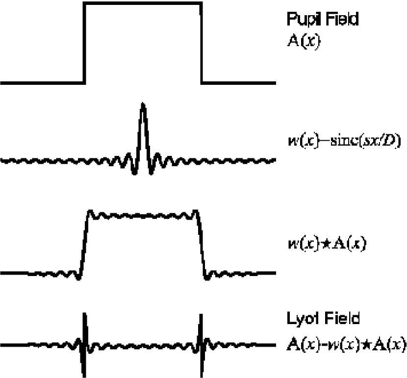
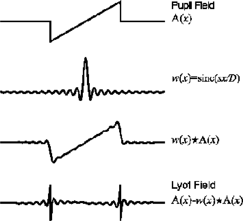
The behavior of these three terms is most easily understood by following this analysis in the case of a band-limited Lyot coronagraph (Kuchner & Traub, 2002). We use a coronagraph with an image plane stop shape function which possesses a FT of , where ( is of the order of a few to , and corresponds to the ‘size’ of the image plane stop in units of ). This simplifies the analytical calculations and brings out the salient features of the manner in which tilt errors propagate through a Lyot coronagraph. For a hard-edged focal stop, is a sinc function (see Figures 2 and 3). Once we are armed with a theoretical understanding of the expressions in equations (5), (6), and (7), we can investigate the response of more common Lyot coronagraph designs to guiding errors numerically, and also start to address how pupil apodization affects the way guiding errors degrade dynamic range.
The zero order term is well-understood for Lyot coronagraphs (e.g., Sivaramakrishnan et al. (2001) and references therein), and is outlined in Figure 2.
3.1 First order tip-tilt leak
The first order term allows light through only at the edges of an unapodized pupil. Such behavior is similar to the zero order term. The leaked light can be suppressed by the usual undersizing of the Lyot stop. In order to see why this is true, one must consider the value of the convolution of the ‘small’ two-dimensional unit-area top-hat function with the function , as shown in Figure 3. Let us consider an x-tilt (by setting ). If inside the pupil, is a flat plane with slope passing through the origin, and containing the axis. The value of the convolution integral when the top-hat function lies entirely within the support of the aperture is simply the value of the offset. Therefore in the interior of the pupil . The electric field further than from the pupil boundary is zero.
A hard-edged focal stop results in leakage of light into the interior of the pupil from the wings of the sinc function (see Figure 3 ). A graded focal stop has a more compact Fourier transform than a hard-edged stop. In this case the interior of the Lyot pupil, where the field remains zero, is larger than that of a hard-edged coronagraph’s Lyot pupil. This results in less sensitivity to tilt error for the same Lyot plane stop geometry at high Strehl ratios, even when the tilt errors are large enough to move the star into regions of the focal stop with significant transmission.
3.2 Second order tip-tilt leak through
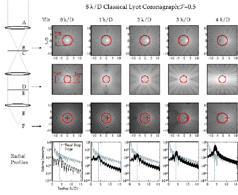
We apply similar logic to the second order term. In the special case of a clear pupil, and the same band-limited coronagraph, the Lyot pupil electric field depends on the difference between and . The convolution integral is no longer the identity operator even when the top-hat function lies entirely within the pupil support. There is a uniform residual field strength approximately equal to everywhere in the interior. There is also the same “bright edge” effect as is seen in the zero and first order terms, but that is removed by the optimally undersized Lyot stop. The uniform background in the pupil plane from the second order contribution of a pure tilt term causes a “ghostly PSF” to form on axis (not displaced) even with an optimized Lyot stop (see e.g. Figure 5). The energy in this PSF varies as the fourth power of the (small) tilt error, and inversely as the fourth power of the focal plane stop diameter. First order effects of defocus will affect the coronagraph in a similar way. It is the combination of these “ghostly PSFs” with the real PSF of the star that results in the distorted images shown in Figure 5.
4 The Point-Spread Functions of a Lyot Coronagraph
Up to this point we have concerned ourselves with small () tip-tilt errors in Lyot coronagraphs. Here we lift that constraint, and examine the morphology of the PSF of a Lyot coronagraph over a wide range of stellar locations relative to the spot center.
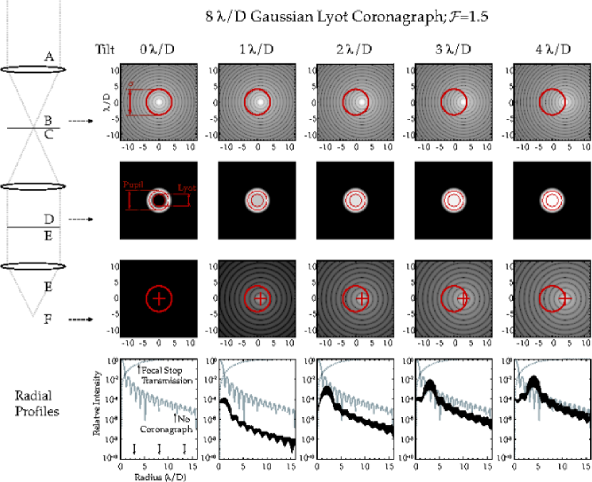
We simulated the PSF of a coronagraph when a star is offset from the center of the stop. These PSFs are illustrated in Figure 5 using a spot in diameter, although we studied both smaller and larger stops. We found markedly different morphologies in three regimes. When the star behind the spot is displaced a small amount, the PSF looks similar to that of the perfectly aligned coronagraph. The rows in Figure 5 show a sequence of locations of the central star, beginning at the very center of the occulting spot, with a Lyot stop diameter 75% of the entrance aperture diameter. When the star is within of the spot edge, the PSF develops outcrops that are not at the location of the star. When the star is located at the very edge of the spot, or outside it, the PSF takes on a typical direct image PSF shape.
The three rows of images in Figure 5 are the PSF in the first focal plane, the Lyot pupil plane intensity, and the final coronagraphic PSF and shown in radial profile. We note the appearance of the fake source located about from the star in the coronagraphic PSF at a misalignment of . The manner in which placement errors interact with higher order errors, such as spherical aberration, has not been studied yet. This suggests that PSF modeling of coronagraphic data should be performed with care to avoid misinterpreting structure close to the spot edge in the image (e.g. Krist et al. (1998); Krist (2004)).
This exercise is relevant to coronagraphy on very high Strehl ratio images, although it also has immediate applicability to coronagraphic science carried out today, with the HST ACS, for instance, if bright structures were present behind the focal stop but near its edge.
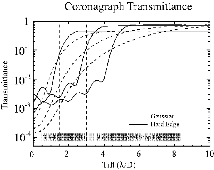
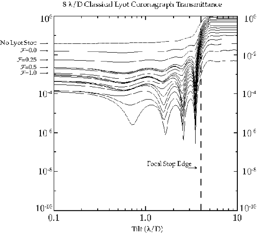
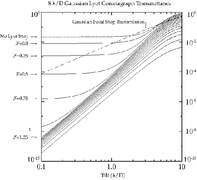
Figure 4 shows coronagraphic rejection efficiency as a function of tilt error for several focal plane stops. Typical coronagraphic reductions of the best current space-based data demonstrate that imperfect calibration data and temporal variations in the PSF set the limits on dynamic range (Krist et al., 1998), so we avoid using simplistic estimates of dynamic range using monochromatic simulations to evaluate the actual effects of tilt errors. We use the fraction of transmitted central source light as a metric of coronagraphic performance. We define the transmittance of a coronagraph to be the integrated light in the final focal plane, excluding the region inside the focal stop (weighted by the focal stop transmission for the Gaussian case). This quantity is directly related to the photon-limited noise, albeit qualitatively. We choose this quantity as a metric for the purposes of this paper in preference to contrast, as it is independent of the choice of an inner working angle for the coronagraph. The transmittance of light is calculated for 3, 6, and 9 focal stops, with a hard-edged Lyot stop undersized by of the pupil radius. A Gaussian apodized focal stop is compared to the hard-edged focal stop. Since the Fourier transform of an apodized stop is more compact, less light bleeds into the center of the pupil (see Figures 2 and 3). It is remarkable that the Gaussian apodized stop is more efficient even in the presence of quite large tilt errors. For example, a FWHM Gaussian focal stop suppresses more light than a diameter hard-edged stop even at tilt (see Figure 4), despite the transmission of the stop being at this radius. The remarkable robustness of the classical Lyot coronagraph is apparent in Figures 5 and 7, contrary to the expectation that led Golimowski et al. (1992) and Lloyd et al. (2001) to incorporated tip/tilt control systems into Lyot coronagraphs. The leakage of light from the central star remains concentrated close to the edge of the image of the focal stop until the central star gets to within a resolution element of the stop edge. This fact, combined with its ease of manufacture and its broad-band performance, makes the Lyot coronagraph interesting even in the era of novel coronagraphic designs, which must all be well-understood in terms of tolerance to the variety of errors that might exist in real telescopes.
The comparison of Gaussian and hard-edge coronagraphs on an equal footing is complicated by the definition of an appropriate equivalent width for the Gaussian stop, and the undersizing of the Lyot stop. For the purposes of comparison, we characterized the width of the Gaussian stop by where the transmission of the stop is . We adopt the convention of Sivaramakrishnan et al. (2001) and define a Lyot tuning paramater which defines the fractional radial undersizing of the Lyot stop in units of (or ). For a hard edges Lyot coronagraph, results in most of the performance benefits of undersizing the Lyot stop, as the Lyot stop excludes the core of the function around the edge of the pupil. Further undersizing in this case results in relatively small gains as the wings of a sinc function decay slowly (this is calculated in detail in Makidon et al. (2000)). For a Gaussian stop, however, the wings are suppressed, and gains continue with further undersizing (see Figure 8). The ultimate application of such tapering of the focal stop to achieve the most compact is the generalization to more arbitrary functions with the concept of the Band Limited Coronagraph (Kuchner & Traub, 2002). The rejection of such coronagraphs continues to improve with extremely aggressive undersizing of the Lyot stop (see Figure 8. To achieve the very high contrast required for terrestrial planet detection a band-limited or gaussian coronagraph with an aggressive Lyot stop () For such a coronagraph (see Figure 6), the near complete rejection of on-axis light is lost with even a small tilt error, but the coronagraph remains robust against tip/tilt errors in the sense that the wings of the PSF are suppressed even for tip/tilt errors of a few .
References
- Golimowski et al. (1992) Golimowski, D. A., Clampin, M., Durrance, S. T., & Barkhouser, R. H. 1992, Appl. Opt., 31, 4405
- Green & Shaklan (2003) Green, J. J., & Shaklan, S. B. 2003, in Techniques and Instrumentation for Detection of Exoplanets. Edited by Coulter, Daniel R. Proceedings of the SPIE, Volume 5170, pp. 25-37 (2003)., 25–37
- Krist (2004) Krist, J. E. 2004, Proc. SPIE 5487, in press
- Krist et al. (1998) Krist, J. E., Golimowski, D. A., Schroeder, D. J., & Henry, T. J. 1998, PASP, 110, 1046
- Kuchner & Traub (2002) Kuchner, M. J., & Traub, W. A. 2002, ApJ, 570, 900
- Lloyd et al. (2001) Lloyd, J. P., Graham, J. R., Kalas, P., Oppenheimer, B. R., Sivaramakrishnan, A., Makidon, R. B., Macintosh, B. A., Max, C. E., Baudoz, P., Kuhn, J. R., & Potter, D. 2001, in Proc. SPIE Vol. 4490, p. 290-297, Multifrequency Electronic/Photonic Devices and Systems for Dual-Use Applications, Andrew R. Pirich; Paul L. Repak; Paul S. Idell; Stanley R. Czyzak; Eds., 290–297
- Lyot (1939) Lyot, B. 1939, MNRAS, 99, 538
- Makidon et al. (2000) Makidon, R. B., Sivaramakrishnan, A., Koresko, C. D., Berkefeld, T., Kuchner, M. J., & Winsor, R. S. 2000, in Proc. SPIE Vol. 4007, p. 989-998, Adaptive Optical Systems Technology, Peter L. Wizinowich; Ed., 989–998
- Malbet (1996) Malbet, F. 1996, A&AS, 115, 161
- Nakajima (1994) Nakajima, T. 1994, ApJ, 425, 348
- Perrin et al. (2003) Perrin, M. D., Sivaramakrishnan, A., Makidon, R. B., Oppenheimer, B. R., & Graham, J. R. 2003, ApJ, 596, 702
- Sivaramakrishnan et al. (2001) Sivaramakrishnan, A., Koresko, C. D., Makidon, R. B., Berkefeld, T., & Kuchner, M. J. 2001, ApJ, 552, 397
- Sivaramakrishnan et al. (2002) Sivaramakrishnan, A., Lloyd, J. P., Hodge, P. E., & Macintosh, B. A. 2002, ApJ, 581, L59