Pulsar shadow as the origin of double notches
in radio pulse profiles
Abstract
We present the model of eclipsing a rotating, spatially extended source of directional emission by a central absorber, and apply it to the pulsar magnetosphere. The model assumes the radially extended inward radio emission along the local direction of the magnetic field, and the pulsar as the absorber. The geometry of the magnetic field lines of the rotating dipole is favourable for the double eclipse events, which we identify with the double notches observed in pulse profiles of nearby pulsars. For pulsars with large dipole inclinations the double notches are predicted to occur within a narrow phase range of before the main radio peak. Application of the model to PSR B095008 establishes it as a nearly orthogonal rotator (, ) with many pulse components naturally interpreted in terms of the inward radio emission from a large range of altitudes. The inward components include the intermittently strong, leading component of the main pulse, which would traditionally have been interpeted as a conal emission in the outward direction. The model also identifies the magnetic field lines along which the radially extended inward radio emission occurs in B095008. These have a narrow range of the footprint parameter close to (closed field line region, near the last open field lines). We describe directional characteristics of inward emission from the radially extended region and compare them with characteristics of extended outward emission. Our work shows that pulse profiles of at least some pulsars may be a superposition of both inward and outward emission.
1 Introduction
This paper addresses two enigmatic phenomena observed in average pulse profiles of radio pulsars: the double notches of B095008, B192910, and J04374715 (Navarro & Manchester 1996; Rankin & Rathnasree 1997; Navarro et al. 1997, hereafter NMS97; McLaughlin & Rankin 2004, hereafter MR04) as well as some puzzling profile components observed in pulse profiles, especially among nearby and/or bright pulsars.
The double notches have the appearance of absorption dips, or eclipse dips: they look as slots carved in a continuous emission pattern, not as the ubiqitous minima between different emission components (NMS97; MR04). The phase at which the double notches occur, their depth, as well as their width weakly depend on the observation frequency (NMS97; MR04).
Although known for almost ten years (Navarro & Manchester 1996; Rankin & Rathnasree 1997), the double notches were interpreted for the first time only recently by Wright (2004). He assumed that they result from absorption of radio waves emitted by a region which is extended over a very large range of altitudes, comparable with the light cylinder radius . This radial extent is obviously manifested by the fact that the notches occur within broad emission features extending over a large range of pulse phase. As demonstrated in many studies of high-energy emission from pulsars, this effect is typical of radially extended emission region (eg. Morini 1983; Romani & Yadigaroglu 1995, hereafter RY95; Dyks & Rudak 2003, hereafter DR03). The precious idea of Wright is that the double notch effect is produced by a single absorber, which provides his model with elegant simplicity. However, the location of the absorber, and the geometry of the emitting regions are far less natural: they are hardly identifiable with any discernible features in pulsar magnetosphere. In this paper we show (Sections 2 and 3) that the single absorber does not have to be located at significant fraction of to be capable of producing the double notch effect. The pulsar itself can do the trick, and the shape of the emission regions can be identical to the shape of the dipolar magnetic field lines.
The pulsar can obviously play the absorber’s role only when the radio emission in the magnetosphere is inward, ie. is directed roughly “antiradially”, towards the neutron star. This is what we assume in this paper at least for the radially extended emission regions responsible for the profile components with the notches. As we show in the accompanying paper (Dyks et al. 2005), the peculiar mode changing observed in B182209 (Fowler & Wright 1982; Gil et al. 1994, see Fig. 4 therein) can be interpreted in terms of emission that sometimes flips its direction by .
In section 3 we apply our theory of double notches to B095008. The information we gain from the model of notches is subsequently used to intepret enigmatic pulse profile components in this object (Section 5).
Perhaps the most puzzling of all components in pulse profiles of pulsars are the interpulses separated from the main pulses by the phase range considerably different from (eg. Manchester & Lyne 1977; Hankins & Fowler 1986). Three different geometries have been proposed to explain this phenomenon, but no one is free from problems. The two-pole interpretation assumes a nearly orthogonal rotator (, where is the dipole inclination, is the viewing angle measured from the rotation axis, and is the impact angle). The main radio pulse (MP) and the interpulse (IP) are supposed to be observed when our line of sight approaches each of the two polar caps and the radio beams aligned with the magnetic dipole axis come into our view. This idea is contradicted by the IP-MP separations significantly different from and by bridges of extended emission which are often detectable only on one side of the MP. The other two interpretations assume a nearly aligned rotator ( a few degrees). One of these nearly aligned interpretations (eg. Lyne & Manchester 1988, hereafter LM88) assumes that the radio beam has a form of a hollow cone centered on the dipole axis. The MP and the IP are observed when our line of sight enters and exits the conal beam. This idea is contradicted by the ubiquitous, large disproportion of intensities of MP and IP, and by the lack of evolution of the MP-IP separation with the observation frequency. Another interpretation relies also on a nearly aligned case (Gil 1983): the radio emission beam is assumed to consist of a few nested hollow cones of different angular radius, centered on the dipole axis. In the course of rotation our line of sight moves mostly between two concentric hollow cones of radio emission, grazing or crossing them at/near two phases separated by 180∘. This interpretation is contradicted by the lack of extended bridges of emission at all pulse phases. The probability of occuring is also an issue for both of these nearly aligned interpretations.
B095008 is a classical example of a puzzling interpulsar. The separation between its MP and IP is considerably different from and there is a bridge of radio emission connecting MP and IP. Section 5.2 provides interpretation of the radio profile of B095008.
2 Model of double notches
In the next two sections we show that the idea raised by Wright (2004), that a single absorption region can produce double notches observed in the pulse profiles of three pulsars described by McLaughlin & Rankin (2004) is generic for the pulsar magnetosphere system. For the inward radio emission the plasma surrounding the neutron star becomes a natural absorbing target and can eclipse the radio emission region. We show that obscuration of a thin-walled, radially extended radio emission region by the pulsar itself can result in double eclipse events. In the entire paper we assume that radio emissivity in the corotating frame (CF) is symmetrical with respect to the magnetic equator (as is the structure of dipolar magnetic field).
2.1 Qualitative description of the double eclipse phenomenon
As an introductory exercise, let us consider the situation shown in Fig 1a: the straight dipole axis is pointing exactly away from the observer, and the inward emission along the axis in the CF points towards the observer. For simplicity, let us ignore refraction and gravitational bending (GB) of photon trajectories. Obviously not all radiation will be eclipsed by the pulsar. In the inertial observer’s reference frame (IOF) the emission direction diverges from the dipole axis (Fig 1b) because the aberration effect projects the emission directions “forwards”, ie. in the direction inclined towards the local corotation velocity .
For the central absorber of radius , the radiation emitted from low altitudes below , is absorbed/eclipsed because of small magnitude of the aberration effect. The radiation emitted above is not absorbed, because it is not directed towards the pulsar in the IOF. Thus, for the eclipse event to occur the emission direction in the IOF (ie. the aberrated CF emission direction) must be close to antiradial. It has to be exactly antiradial if the size of the absorber is negligible in comparison with the radial distance of the emission: .
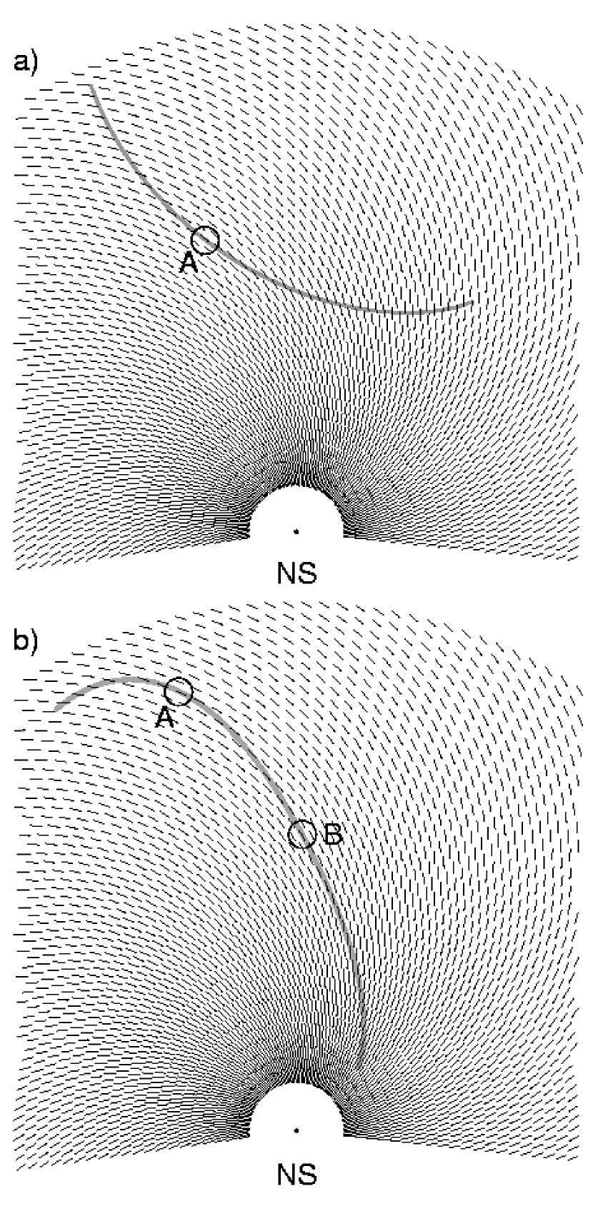
Now we consider a more general situation, which will open the possibility of the double notch effect. For simplicity we assume that and we consider a two-dimensional plane perpendicular to the rotation axis (eg. the plane of the rotational equator). Fig. 2a presents the small absorber embedded in the corotational velocity field . For every point in the magnetosphere, this velocity field uniquely determines the “absorbed direction”, ie. a direction of photon emission in the CF, which becomes antiradial after being transformed to the IOF. Thus, the velocity field in the IOF unambiguously determines the field of absorbed directions in the CF (Fig 2b). Radiation emitted along the absorbed direction in the CF will be absorbed and will not reach the observer.
Fig. 3a presents a thin and radially extended radio emission region (grey arch) embedded in the field of absorbed directions (both are shown in the CF). The region should be considered as a two-dimensional surface. Our figure only shows its cross-section with the equatorial plane. We assume that in the CF the radio waves are emitted tangentially to the emission region, in some preferred direction on the emitting surface. In Fig. 3 the tangent direction of emission is assumed to be contained within the equatorial plane. Radiation from point A of the region will be absorbed, because it is emitted parallel to the local absorbed direction. In consequence, a single notch will be observed. Fig. 3b presents a single extended emission region which will produce double notches: the local absorbed directions are parallel to this region in two places: A and B.
As long as one is free to choose any emission region, it is hard to imagine any system of notches which could not be interpreted in the above described way. However, it is important to check whether the observations can be reproduced using an emission region which has the same morphology as the underlying shape of magnetic field lines. Below we seek for such regions of dipolar magnetosphere which naturally produce the double notch effect. In the next section we describe a rectilinear model of eclipsing an extended emission region by the pulsar.
2.2 Eclipse condition
A simple condition for the “central eclipse” of a photon emitted at location and direction tangent to the local magnetic field in the CF, is that the photon’s emission direction in the IOF must be opposite to radial:
| (1) |
where ,
| (2) |
| (3) |
and represents the Lorentz transformation of the photon propagation direction from the CF to the IOF111More exactly: from the Lorentz frame instantaneously comoving with the emission point to the IOF.:
| (4) |
(DR03), where and . The central eclipse condition (1) is not affected by the GR effects as long as the metric around the neutron star (NS) has no strong azimuthal dependence (eg. is close to Schwarzschild). The values of provided by condition (1) define the center of the “blocked regions” – regions in the magnetosphere such that no inward radiation emitted from there can reach observer because it is obstructed by the pulsar from our sight. In Fig. 3 the blocked regions were marked with the letters A and B. The blocked region has the width determined by the condition:
| (5) |
where is the “effective” radius of the central absorber (the NS or the opaque plasma cocoon surrounding the NS). In the absence of the plasma cocoon, refraction, and gravitational bending (GB) of photon trajectories, we would have . With the GB included because on their way towards the NS, the photons’ trajectories bend towards the axis connecting the center of the neutron star and the emission point. If the NS is embedded in the cocoon of plasma (Michel 1991; Melatos 1997) which is opaque for the radio waves, it may well be the case that and GB is negligible. Eq. (5) is a more general eclipse condition than eq. (1). It reduces to eq. (1) in the limit .
The observer located at direction will detect the shadows of the pulsar at the pulse phases at which the photons would have reached him had they not been absorbed by the NS:
| (6) |
where is the azimuth of in the reference frame with the observer in the plane, the second term is the flat spacetime propagation time delay and is the correction due to the Shapiro delay effect. The minus sign at simply takes into account the fact that larger azimuths in the CF correspond to earlier detection times.
The vector field of absorbed directions which we described in the previous section, is given by:
| (7) |
2.3 Failure of the small angle approximation
In this section we use eq. (1) to search for the double notch effect assuming the small angle approximation. Wright (2004) was able to prove that a single absorber can produce double eclipse phenomenon, in spite of the fact that he used the small angle approximation at very high emission altitudes. Following this simple approach222With the neutron star playing the role of the absorber the small angle theory actually becomes much simpler than in the case considered by Wright (both the source and the absorber in motion)., we constrain our considerations to the strictly orthogonal rotator () and we aim for explaining the double notch system of B095008. Among the three “notched pulsars” described by McLaughlin & Rankin (2004), this pulsar has the largest probability of being the “roughly orthogonal rotator”. The position angle (PA) curve of this pulsar (eg. Fig. 4 in MR04) is typical for “poleward viewing” (see Everett & Weisberg 2001, hereafter EW01) which is improbable for nearly aligned pulsars. EW01 find for this object. Becker et al. (2004) interpret the X-ray pulse profile of B095008 and also conclude that it is a roughly orthogonal rotator.
We need to define a “footprint parameter” , where is the magnetic colatitude of the point at the NS surface crossed by a considered magnetic field line. We assume a thin-walled, radially extended emission region with the same geometry as the surface formed by the magnetic field lines with some fixed . For orthogonal rotator and equatorial viewing geometry (, ), as well as in the limits of small angle approximation (small where is the distance of emission point from the dipole axis), the eclipse condition (1) becomes:
| (8) |
where is the angle between the CF emission direction and the dipole axis [], is the angle between and , and is the aberration angle between and . The equation refers to the leading side of the open field line region, and the ambiguity of the sign takes into account the fact that the direction of is opposite within the two magnetic hemispheres. Thus,
| (9) |
which for fixed has only one solution that fulfills . This shows that for a radially extended emitting surface formed by magnetic field lines with the same (thin walled “funnel” or “tube” centered on ) it is possible to observe only a single eclipse event, at least in the limit of small angle approximation (ie. for small or ) and for the orthogonal geometry we considered.
2.4 Numerical method
It is then obvious that for highly inclined rotators, only the emission region located far from the dipole axis, for which the small-angle approximation breaks down, has the chance to result in the double eclipse events (double notches).
We use the following numerical method to identify the blocked regions in the dipolar magnetosphere of a pulsar, and to calculate the phases at which the notches can be observed: 1) We assume that the structure of the magnetic field can be approximated by the rotating vacuum dipole without the general relativistic effects. We use eqs. (A1) – (A3) from Dyks & Harding (2004) to calculate and then eq. (3) from section 2.2 to get . 2) We choose some value of and we identify all magnetic field lines which have this (for details see section 2.2 in Dyks et al. 2004, hereafter DHR04). 3) We assume some value of (usually between a few and , Melatos 1997) and check whether the condition (5) is fulfilled anywhere along the field lines we selected above. We probe the region of fixed which simultaneously fulfills the following conditions: , , and , where is the distance measured from the rotation axis, and is the distance from the plane of the rotational equator. Typically we take , , and . When the condition (5) is fulfilled, we record the spatial coordinates of such “blocked region” and the direction of emission from eq. (4). 4) From we calculate the azimuth of the emission direction as well as the direction towards the observer who will detect this eclipse event: , . These are used in eq. (6) to calculate the phases at which the observer will detect the eclipse events. is assumed.
3 Numerical results
To make clear visualization possible, we first discuss results of a two-dimensional calculation limited to the equatorial plane. As argued above, this kind of calculation should be able to reproduce the double notches of B095008, which is expected to be a highly inclined rotator. To discuss numerical results for the retarded dipole with non-circular polar caps, we must generalize the definition of the footprint parameter to: where is the magnetic colatitude of the rim of polar cap measured at the same magnetic azimuth as the azimuth of the footprint point. The definition is the same as in Yadigaroglu (1997) and Cheng et al. (2000, hereafter CRZ00). For considerably different from , we use the open volume coordinate , for the reasons specified in DHR04. One can usually assume that .
3.1 Equatorial plane of orthogonal rotator
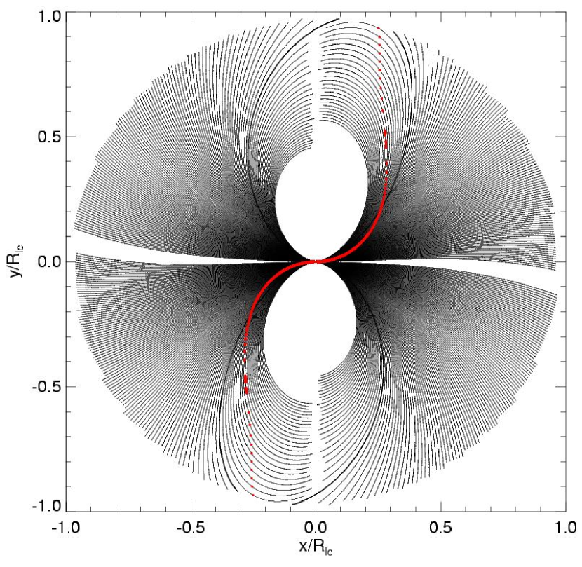
As long as our “region of interest” is limited to the open field line region within the light cylinder, the application of the above-described numerical method to the equatorial plane of orthogonal rotator gives negative result: open field lines with two solutions for the eclipse condition (5) do not exist – double notches cannot be produced by a funnel of fixed located within the OFLR, at least in the orthogonal case. However, it is sufficient to search on the closed field lines which are located nearby the OFLR (ie. which have only slightly larger than ) to find those which fulfill the eclipse condition (5) at two different altitudes. Fig. 4 presents selected magnetic field lines of the retarded dipole in the equatorial plane. Those marked with thicker lines are the last open field lines which have . The numerically calculated blocked regions are shown with red dots. The blocked regions associated with different field lines form two “blocked stripes”, each of which is associated with a different magnetic hemisphere. The blocked stripes have actually a continuous form – one has to connect the dots to have a correct view of them. As expected, the blocked stripes are located on the leading side of the OFLR. This is because in the dipolar the eclipse condition can only hold on field lines which bend towards the rotation direction. For lines bending backwards, the aberration cannot make the CF emission direction antiradial in the IOF.
The magnetic field lines shown in Fig. 4 have within the range and differ in by . This allows us to easily identify for each field line, just by counting the lines starting from the last open ones. In this way one can find that the field lines which are eclipsed at high radial distances () have . Those which are eclipsed two times have between and . One can identify two blocked regions on each of these lines. For increasing (ie. when one selects lines located deeper and deeper within the closed field line region) the two blocked regions on a given field line approach each other. For they merge into a single region.
For very close to (and ) the two blocked regions on a given field line are located very far away from each other: one of the regions is at whereas the other one is close to the light cylinder. This gives a (misleading) impression that the phase separation between the eclipse events (between the notches) will change considerably for emission from funnels with different . This conjecture is wrong.
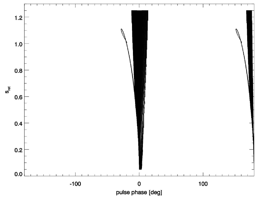
Fig. 5 presents the phases of eclipse events calculated with the help of eq. (6) for lines with different (vertical axis). was assumed. The zero point of phase corresponds to the phase of detection of the low altitude radiation emitted along the dipole axis. The precise definition of this fiducial phase is given at the beginning of section 3 of Dyks & Harding (2004). Fig. 5 then tells us that for the double eclipse event (double notches) occurs at some before the main radio peak, just where it is actually observed for B095008 (see Fig. 1 in MR04). The double eclipse can occur only when the inward radio emission occurs at closed magnetic field lines located very close to the OFLR, with between and . We do not consider this a problem because is clearly an upper limit on the size of the corotating zone (Cordes 1978). For the retarded dipole and for the two eclipses are perceived almost simultaneously, so that the range of for which easily discernible double notches can be produced is . This conclusion is nevertheless sensitive to the assumed geometry of the dipolar magnetic field. Another important conclusion is that for the double notches can occur only within a very narrow range of phase, which precedes the main peak. There are no double solutions of the eclipse condition (eq. (5)) on the trailing side of the main peak. Actually, far on the trailing side of the main peak there are no solutions for the eclipses at all (including the single ones). The separation between the eclipse events calculated for a funnel of fixed , ie. for a horizontal line crossing the loop in Fig. 5 is a bit smaller than what is observed for B095008 ( versus ). However, it is sensitive to the assumed structure of in the vicinity of the light cylinder. The range of phase at which the notches occur (leading side of the main pulse), is much less sensitive to this.
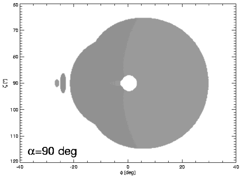
Fig. 6 shows the distribution of the eclipsed radiation on the plane for , and cm. In other words, the grey areas present regions on the plane within which the eclipse condition (5) is fulfilled if the funnel of is assumed as the emission region. The spots are thus shadows of the pulsar projected on the plane. The observer’s line of sight cuts the shadow spots horizontally, at fixed . The two small shadow spots responsible for the notches are located near and precede in phase the large shadow which corresponds to the low altitude emission. The blank spot in the center of this shadow appears because the emission is radiated from the funnel with . There is no emission from the inner parts of the funnel, and therefore333When interpreting figures like Fig. 6 one has to keep in mind that the lack of shadow may have two reasons: 1) the emission detected at some point on the plane is not obscured; 2) no emission is directed towards this point on the plane. In the case 2) we cannot see the shadow but it is not excluded that if the radiation had been emitted towards the point it would have been obscured, and the shadow would have appeared there. The important general rule is that what is absorbed depends not only on the characteristics of the absorber, but also on what is emitted (ie. on the little known characteristics of the high-altitude radio emission region). A presentation of emitted radiation on the plane (with shady spots here and there) does not solve this problem because the depth of the shadows has a very different dynamical range than the intensity range of emitted radiation. This is one of the reasons for which it is so hard to notice the double notches for B095008. The double notches in its pulse profile are actually imprinted in a low intensity layer of emission from high altitudes which is superimposed on a high level of emission of the main peak. The double notches of B192910 most probably are not superimposed on independent emission of different origin and this makes them so pronounced (provided that the instrument is sensitive enough to detect this weak emission). Another viewing-related problem (other than the different dynamical scales of shadow depths and intensities) is that it often happens for a few emission layers as well as for a few shadows to overlap in pulse phase. For example, the two small shadow spots tend to overlap with the large deep shadow produced by the low altitude inward emission. no shadow at , . Note that Fig. 6 was calculated for the fixed . Therefore, a horizontal cut through Fig. 6 at nearly corresponds to a horizontal cross-section of Fig. 5 at (the correspondence would be exact if the same value of had been used both in Fig. 6 and 5).
3.2 Non-orthogonal, highly inclined rotator
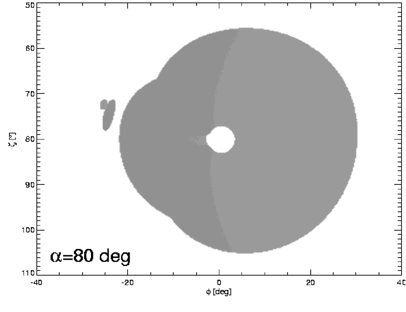
Because the case of is a very specialized one, it is necessary to confirm that the double notch effect survives for . Fig. 7 presents the distribution of shadows for , , and cm. Two shadow spots responsible for the double notch effect stay close to each other at . They are no longer at the same as the magnetic pole. They have and can only be observed in the case of poleward viewing geometry. This is in full agreement with the “poleward shape” of position angle curve exhibited by B095008.
3.3 The spread in
The results presented above were obtained for a single value of . The actual emission region in pulsar magnetosphere is most probably extended across and occupies a range of . For funnels with slightly different , the pair of notch spots has slightly different location on the plane and the relative orientation of each spot in the pair is a bit different.
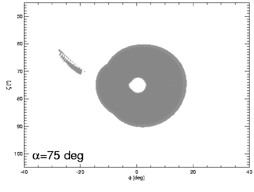
Fig. 8 shows the distribution of shadows for , cm and in the range with a step of . Because of the spread in each of the notch spots forms its own band of shadow, extending both in as well as in . The extension in the direction considerably increases the probability of detection of the double notches. The two bands of shadow cover in the direction, which is twenty times more than the angular diameter of the absorber viewed from .
If the radially extended emission region is also extended in , then each notch in the observed pair is actually a superposition of shadows corresponding to different . Each of these notches consists then of many “subshadows” imprinted in emission originating from different altitude, ie. corresponding to different red points in Fig. 4. Therefore, the shape of the double notches (or any notches in general) depends on the emissivity profile along, and across the magnetic field lines, which complicates numerical modeling. The width and depth of the notches may also be affected by . In the limit of the infinitely narrow range of , the simple-minded method of determining the width of notches () reproduces the results of numerical simulations obtained for a single values of . It must be remembered, however, that the actual shadows are most probably a convolution of emission and absorption from different regions of the magnetosphere.
3.4 Moderately inclined and nearly aligned rotators
The other two pulsars with notches – B1929+10 and J0437-4715 probably have smaller dipole inclinations than B095008. The position angle curve of B192910 implies equatorward viewing geometry, which is improbable for close to . J04374715 has a pulse profile expected for the nearly aligned rotator (NMS97).
At the present stage of developement, our numerical codes are not suitable to identify the blocked regions responsible for the double notches of these objects. It is quite easy to check, however, whether any shadows can appear in the region of phase trailing the main radio pulse. We do this by moving from point to point within the entire volume of the light cylinder, and checking at each point whether the eclipse condition (5) is satisfied. When it is, and are calculated as described in section 2.4. This method does not provide the information on and one cannot discern whether or not the magnetic field lines penetrating the blocked regions can form the surfaces with geometry favourable for the double notch effect. However, the method allows us to calculate quickly the regions of shadow on the plane for different inclinations .
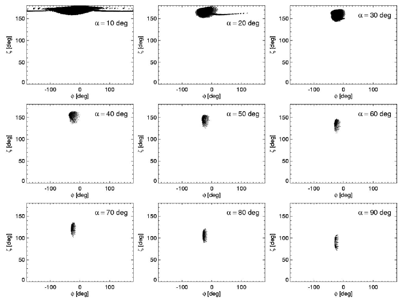
The result is shown in Fig. 9 for different values of between , and , , and . Inward emission from only one hemisphere is included. One can see that for the possibility of detection of pulsar shadow appears on the trailing side of the main radio peak.
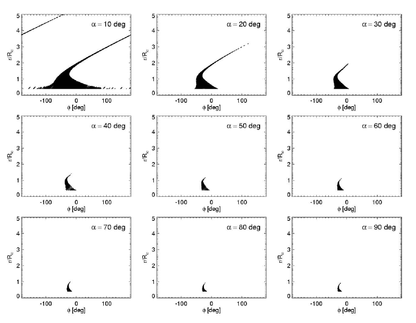
Fig. 10 presents how the same blocked regions map onto the space , where is the radial distance of emission from the blocked region. One can see that the shadows which appear on the trailing side of the main peak for small are imprinted in emission from very high (but ). The reason for which the shadows are expected at so late phases is that the propagation time delay (2nd term in eq. 6) becomes larger for increasing .
Among the two pulsars with notches on the trailing side of the main pulse, J04374715 is consistent with the nearly aligned rotator, with proposed as small as (Gil & Krawczyk 1997; cf. NMS97). B192910, however, has probably quite large dipole inclination (Rankin & Rathnasree 1997; Wright 2004) and poses a problem for our model.
4 Frequency evolution of double notches
The appearance of the double notches depends on the properties of the absorber and of the emission region. Navarro et al. (1997) reported two types of slight frequency evolution for J04374715: at lower frequencies the notches broaden and become more separated. The change of separation must result from the properties of the emission region, not of the central absorber. As one can see in Fig. 5, for different the separation between the notches changes slightly. Apparently, the emissivity profile across the magnetic field lines has a maximum at which is different for different frequencies. The increased width of the notches at the lower may be caused by larger . The “radius of transparency” of a plasma cocoon surrounding the neutron star, would be larger at smaller , if the plasma density decreases with .
MR04 noted that the double notches of B095008 tend to disappear at high frequencies (cf. Fig. 2 and Fig. 3 therein) or at the same but a different observation time. According to our model, the double notches are imprinted in bumps of caustically enhanced emission (see the figures and comments in the next section), which may (but do not have to) be superposed on an underlying emission of different origin. If the spatially extended radio emission ceases at high frequency (or at the same but different observation time), the bump in which the double notches are immersed (and so the notches) will disappear.
The dependence of the notch width on the (frequency dependent) radius of the central absorber is obviously worth of closer inspection because it may provide invaluable information about the central object. However, this is a very complex subject which requires exact, 3-dimensional modeling of the emission region. Various intensity profiles along and across must be tested, and gravitational bending of photon trajectories must be included to model the cases with . Possibly refraction has to be included too. Simulations of this kind will be the subject of our future study.
5 Pulse profile of PSR B095008
In this section we present an unorthodox, yet natural interpretation of the radio pulse profile of PSR B095008. Two component radio emission region is assumed: in addition to a strong and narrow beam of radio emission along the dipole axis we assume a thin, radially extended fan/funnel of weak inward emission from magnetic field lines with . We assume that radio emissivity in the CF is perfectly symmetric with respect to the magnetic equator, i.e. the two magnetic hemispheres have identical emission pattern. We associate the dipole axis beam (DAB) with the main radio pulse but we do not specify whether the DAB is an outward emission, an inward emission, or a mixture of both. We do not exclude the possibility of inward emission for the DAB. It is also possible that the funnel and the DAB are different parts of a single, continuous emission region. In the next section we discuss the funnel component.
5.1 Inward emission versus outward emission – general remarks
The idea of inward emission in pulsar magnetosphere is not new. However, it was never studied in great detail because of a lack of firm observational evidence for it, and the literature on this subject is scarce and limited (e.g. Cheng et al. 1986; Yadigaroglu 1997; Wright 2003). Radially extended outward emission from fan or funnel-like emission regions is much better understood (Morini 1983; RY95; Yadigaroglu 1997; CRZ00; DR03) and appears to be quite successful in explaining gamma-ray profiles of pulsars.
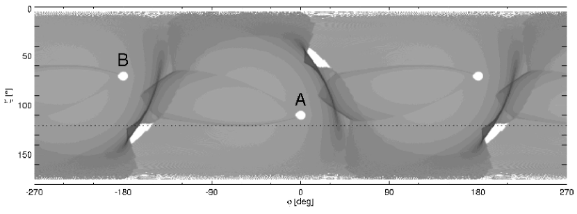
Fig. 11 presents the pattern of outward emission on plane, calculated for , , , and . The emissivity was assumed to be uniform per unit length of the magnetic field lines. One and a half of period is shown. The blank spots at and correspond to two opposite polar caps and are marked with the letters A and B. Each of them is embedded in a continuous emission pattern originating from the same magnetic hemisphere as the considered cap. A horizontal cut through the figure at a fixed produces a lightcurve for a single observer. The flux received at a given phase increases with the darkness of the pattern.
Fig. 11 illustrates that the outward emission from a large range of altitudes on the leading side of the OFLR gets spreaded over a very large range of phases () preceding the polar cap (and the DAB). The outward emission from a large range of altitudes on the trailing side of the OFLR gets cumulated within a very narrow range of phase, just behind each of the polar caps in the figure (dark arches at , , and ). This pile up of photons on the trailing side of the OFLR is a well known effect of purely caustic origin, as described in Morini (1983) and subsequently employed in various models of high energy emission from pulsars (eg. outer gap model, RY95; two-pole caustic model, RD03).
The dotted horizontal line in Fig. 11 cuts through the outward emission which is detected by an observer located at . The observer’s line of sight makes the closest approach to the magnetic pole A at phase where the main radio peak (MRP) is expected. In addition to the two caustic peaks at and the observer detects emission extended over a large range of phase. As emphasized by RY95, the brightest extended emission (usually called the “bridge” emission) occurs after the MRP, in the phase range . The extended emission is weaker within the phase range preceding the MRP () which is called the “off-pulse” region. This is a common feature of pulsar profiles observed at gamma rays (Kanbach et al. 1994; Thompson 2001; Grenier et al. 1988; Ulmer et al. 1995; Kuiper et al. 2001; Fierro 1996) which apparently are dominated by the outward emission.
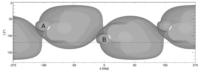
Fig. 12 presents the emission pattern from the same magnetic field lines as in Fig. 11, but this time the emission is inward. The generic features of the inward emission pattern are the following: 1) The caustic pile up of photons emitted from a large range of now precedes the main radio peak in phase and occurs on the leading side of the OFLR. 2) The spreaded emission now occurs on the trailing side of the MRP. 3) The bridge emission precedes in phase the MRP. 4) The off-pulse region follows the MRP.
Thus, because of the change of emission direction most of the emission properties that follow from such effects as finite wave propagation speed, aberration due to rotation – gets reversed. For example, the relativistic shifts of pulse components, described in Dyks et al. (2004a) and Gangadhara & Gupta (2001) occur in the opposite direction if the inward emission is assumed.
Another feature of the inward emission map on the plane is that the patterns of emission associated with different magnetic hemispheres switch their places in comparison with the outward case. Thus, the polar cap marked with “A” in Fig. 11 is associated with inward emission pattern which surrounds “A” in Fig. 12. Or: if the low altitude outward emission (from the vicinity of the NS) is located near some , the inward emission from exactly the same region will be located at .
5.2 Radio profile of B095008
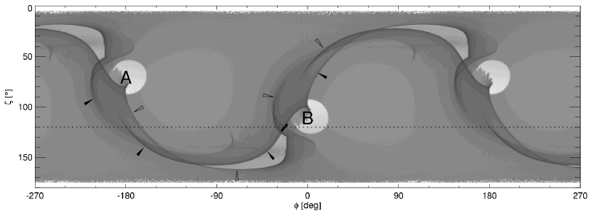
The interpretation of the double notches we present in Section 2.2 tells us that the radially extended regions of weak radio emission are located at field lines with . Fig. 13 presents the inward emission pattern for and . By comparison with the previous figure for , we learn that many details of the pattern changed, but the generic features discussed in the previous section (location of the caustic peaks, and of the bridge, with respect to the MRP) persist for . Since the bridge observed in the pulse profile of B095008 precedes the MRP we conclude that the bridge is the inward emission.
To identify the origin of the other components in the profile, we draw a horizontal line at for the observer who can detect the double notches (the region in which they appear is marked with short thick dash left of the pole B). One can see that the notches are embedded in the caustically enhanced region of emission, or a bump, as observed. This feature is inherent for our mechanism of the notch generation: at low r the radially extended emission surface must emit radiation which passes on one side of the pulsar, then, at higher altitudes on the other side, and then again on the initial side at still higher altitudes (these three regions of emission which passes on both sides of the pulsar are separated by the two blocked regions; in Fig. 4 they can be identified with three sections of a single magnetic field line separated by two red dots).
One can see that the trajectory of the observer’s line of sight (the horizontal line in Fig. 13) crosses two regions of emission enhanced by the caustic effects (dark arches): 1) near which we identify with the interpulse, and 2) near which we identify with the notched bump described above. Caustic enhancements of emission associated with both magnetic poles are located near each of those phases. The caustic arches associated with the pole A are marked with the filled arrow tips, whereas those associated with the pole B are marked with the blank arrow tips. In the case of the notched bump emission we have no doubts that it is associated with the emission pattern from the pole B. A contamination from high-altitude pole-A emission cannot be excluded, however. In the case of the interpulse the situation is less clear. If the radio emissivity decreases with increasing , the IP is dominated by high-altitude emission associated with the pole A.
Note that all the caustic features crossed by our line of sight roughly overlap in phase with the difficult-to-understand components we observe in B095008 (the interpulse, the bridge, and the notched bump on the leading side of the MRP). The tendency of the modeled IP to be splitted into two or three subcomponents is also noteworthy.
We conclude that the enigmatic components in the profile of B095008 are consistent with radially extended, weak, inward emission from lines with . The shapes and locations of these components are mainly determined by the caustic effects. The pulsar is a nearly orthogonal rotator with and . The interpulse originates from very high altitudes, comparable to .
Hankins and Cordes (1981) noted a very interesting correlation between the MP and the IP: after a bright MP, a bright IP appears in the next pulse. A similar phenomenon can be identified in B1055-52 (Biggs 1990). Our geometrical model, with interpulse orginating from high altitudes, suggests that this effect is caused by the propagation time delay associated with information transferred from low altitudes upwards.
6 Polarization
Because the projection of on the plane of sky does not depend on whether we observe the inward or outward emission, we do not expect significant modifications of the simple polarization model of Radhakrishnan & Cooke (1969) and Komesaroff (1970), provided that both the inward and the outward emission represent the same mode of radio waves.
However, the polarization model of Blaskiewicz et al. (1991, hereafter BCW), which takes into account the corotation, is affected significantly. The BCW model can be summarized as follows: for emission from increasing altitudes the position angle (PA) curve is shifted towards later phases. The shift, as measured with respect to the fiducial zero phase, is equal to rad, as long as the emission altitudes are not too close to the light cylinder (Dyks et al. 2004a).
It can be shown that the corotation has the exactly opposite effect on the PA curve if the inward emission is considered: for increasing the PA curve is shifted towards earlier phases by rad.
Our model assumes that the extended emission components/bridges are the inward emission which on average originates from higher altitudes than the main peak. Thus, the standard S-curve fitted within the phase range which does not include the main pulse should reflect this anti-BCW shift toward earlier phases. This should manifests itself in two ways: 1) The inflection point of the S-curve fitted to the high-altitude emission should be located at earlier phase than the main pulse. This is exactly what happens for B095008 and B192910 and is obvious in Figs. 8, 9, 10, as well as 16 and 17 in EW01. 2) The PA data points observed under the main peak should therefore be located on the right hand side of the S-curve fitted to the high-altitude emission. This effect is less pronounced but can also be discerned in Figs. 9, 16 of EW01, as well as in Fig. 11 of Rankin & Rathnasree (1997).
Our value of is different from preferred by EW01. We expect some discrepancy, because according to our model, emission at various phases originates from different altitudes. Therefore, application of the standard rotating vector model to different ranges of phase can give different values of , e.g. EW01 find for the phase range including interpulse.
The basically continuous shape of the observed PA curve may at first glance appear disturbing, because of overlapping contributions from two disconnected regions on opposite sides of the star. However, for the sharp changes of PA to occur, the overlapping components must be polarized at significantly different angles, and the ratio of their linearly polarized intensities must vary very fast. Such conditions may be, but do not have to be, fulfilled. The difference of PA is alleviated by the fact that the projection of on the plane of sky is the same for inward and outward emission.
7 Inward emission within the main pulse
We have found three independent arguments, which support the inward direction of emission detected as the IP, the bridge, and the notched bump in B095008: 1) the bump contains the double notches, which we interpret as the shadows of the pulsar; 2) the geometry of the emission region implied by the theory of the double notches naturally reproduces the locations of the IP, the bridge, and the notched bump; 3) the S-swing of the high-altitude PA curve reveals the anti-BCW shift.
With so many components consistent with the inward emission, a natural question emerges: is the emission of the main pulse inward too? It is not easy to answer this question with the help of the above-mentioned methods: Although we clearly see the trend for some kind of “notches” to appear also at the maxima of the main pulses (MR04), it is hard to discard the alternative, traditional explanation in terms of “multiconal” outward beam structure. Another problem is that both the inward and the outward emission from low alitudes are not affected by the relativistic phase shifts, which are so sensitive to the flip of emission direction and which allowed us to interpret the IP and the bridge.
Therefore, we base our reasoning on intensity correlations between different components: Fig. 1 in MR04 reveals that the strongest part of the main radio pulse of B095008 is splitted and consists of two components, which can be easily discerned at 430 MHz. The intensity of the leading component is clearly correlated with the intensity of the IP, the bridge, and the notched bump. This can be seen both by inspecting two different profile modes at the same frequency of 430 MHz (cf. Figs. 1 and 2 in MR04), as well as by comparison of profiles at different frequencies (cf. Figs. 1 and 3 therein). It is obvious that the leading peak in the main pulse disappears together with the components which we identified as inward emission. It is natural to conclude then, that the main pulse of B095008 includes a component produced by the inward emission. A look at our Fig. 13 reveals that the leading component of the MRP may be either a low altitude emission from the pole B, or a high altitude emission from one of the poles (most probably from A). A search for correlations between different components in a single pulse data may solve this ambiguity.
A similar phenomenon (weakening of conal components along with the extended inward components at increasing frequencies) can easily be recognized also for J04374715 (Figs. 1 - 3 in NMS97), and for B192910 on the trailing side of the MP and IP (Figs. 5 and 6 in MR04).
7.1 Profile mode changes
The trailing component of the main pulse of B095008 (the one which survives at 1475 MHz in Fig. 3 of MR01) may be the inward or the outward component. If it is outward, then the immediate conclusion is that the main pulse of pulsar profiles consists of both the outward and the inward emission, with the latter appearing intermittently. Thus, we propose a time dependent ratio of inward and outward emission as a reason for the “long-term mode changing” visible in Figs. 1 and 2 of MR04. The more common abrupt changes of profile shapes may well have a different origin, most probably resulting from sudden changes of drift pattern (Wright 2003). However, the peculiar profile mode changes of B182209 have also been interpreted in terms of inward emission, as reversals of radio emission direction (Dyks et al. 2005).
It is worth to note that the two open field line regions above each polar cap, as well as the direction of which permeates them, are all aligned roughly on one axis, so that if any of them emits inward, it will contribute to the outward emission from the other region. The neutron star, probably surrounded by the dense plasma will be on the way, which naturally produces the hollow cone shape of the radio beam. The plasma may lead to birefringent refraction, possibly responsible for the existence of the two orthogonal modes (eg. Lyubarski & Petrova 1998; Petrova 2000; Fussell & Luo 2004).
8 Conclusions
Our main conclusions are:
1) We find that the geometry of dipolar magnetic field is favourable for the double eclipse event to occur provided that inward emission is present in pulsar magnetosphere in addition to canonical outward emission. For nearly orthogonal rotators, with to , this double notch effect occurs to before the main radio peak. This effect may be, thus, responsible for the double notches observed for B095008.
2) The existence of double solutions for the eclipse at the leading side of the MRP (Fig. 5) comes then naturally from the following simple assumption: the inward emission is tangent to the dipolar magnetic field in the CF. By probing the entire volume of the light cylinder, we have only identified the location of the obscured regions in the magnetosphere, and we calculated the corresponding phases of eclipse events.
3) The double notch effect requires that the region of inward emission extends over a large range of altitudes and is relatively thin. For the highly orthogonal rotators it is the thin-walled funnel formed by the magnetic field lines with to . These lines are located within the closed field line region, but close to the last open field lines.
4) The simple geometry of emission in our model approximately reproduces the locations of both the absorption and the emission features in the pulse profile of B095008. Based on this agreement we argue that PSR B095008 is a nearly orthogonal rotator with to and .
5) The radio emission mechanism should be capable of producing radio emission of a given frequency over a considerable range of altitudes ().
6) The extended, inward radio emission from the spatially elongated region is of very low intensity, and can be detected only from nearby pulsars (like B095008, B192910). For the closest pulsars, however, it is this emission which is most probable to get into our view. It is possible to miss the strong radio beam along the dipole axis but still detect this weak “fan” emission. There should be a population of dim nearby pulsars with unusual pulse profiles. Some of them may have the main radio peak missing and may only posses extended, bridge-like emission components (possibly hard to detect).
7) The radial extent of the radio emission region unavoidably implies that the appearance of some components in pulse profiles is governed not only by the spatial distribution of emissivity, but also by the caustic effects. We identify the interpulse of B095008 as a radio peak of caustic origin. The notched bump before the main peak is of the same origin. The caustic, high-altitude nature of the IP means that B095008 is a kind of a “false interpulsar”, with the IP generated in a different way than those described in Introduction. Fig. 13 demonstrates that the probability of observing such “caustic interpulsar” is very large: most horizontal cuts through the figure correspond to lightcurves with interpulses. However, because the fan/funnel component of the radio emission is weak, the caustic interpulses should be detectable only from the nearest pulsars. Interestingly, most known interpulsars are close objects (Manchester et al. 2005).
8) We interpret the enigmatic components in the pulse profile of B095008 as inward components. The strong, leading component in the main pulse correlates with them and apparently is also the inward emission. This interpretation implies that the long-term profile mode changes observed for B095008 are generated by time-dependent contributions of inward emission to the outward beam.
9) With the bridges of high-altitude, low-intensity emission connecting smoothly with the main radio peaks, the geometrical method of determining the radio emission altitude breaks down, especially if the pulse width is measured at the “lowest detectable” intensity level (Kijak & Gil 2003). Given that the radio emission region for a given frequency extends over a large range of altitudes and at least for some objects has the form of the fan beam, the principle underlying the method needs to be reconsidered. The pulse width measured at the lowest detectable emission level may at best correspond to the radial distance from which this edge/wing emission is measured (if the actual is close to 1). It may have little, or nothing to do with the altitude from which the bulk of emission in the main pulse originates.
10) For the same reason the delay-radius method of determining breaks down. Not only the emission does not originate from a fixed altitude, as assumed in BCW, but the pulse profiles posses inherent asymmetry caused by the contributions from high-altitude inward components (eg. the notched bump in B095008 broadens the left wing of the main peak and destroys any low altitude symmetry which the main peak might otherwise posses).
11) The strongly asymmetric pulse profile of B095008 is produced by the purely symmetric emission region which follows the symmetry of the dipolar magnetic field. No “higher mutipoles” or “sunspot-like” structures (eg. Gil et al. 2002) are required to understand it. It is the rotation which naturally breaks the symmetry.
12) The locations of components, bridge and double notches in the pulse profile of B095008, as well as the occurence of the anti-BCW shift in B095008 and B192910, all can be interpreted in terms of the inward radio emission. The two-directional emission can also be inferred from the peculiar mode changes of B182209 (Dyks et al. 2005). Apparently, some radio data are less difficult to interpret if one admits inward emission in pulsar magnetosphere.
9 Discussion
The inclusion of the inward radiation into the radiation generation scheme opens new possibilities that can help explaining the variety of pulsar radio profiles (Rankin 1983; Lyne & Manchester 1988; Kramer et al. 1998; Xilouris et al. 1998; Gould & Lyne 1998; Weisberg et al. 1999). Among others, refraction and reflection of radio waves in plasma are the processes that we are looking forward to analyze in greater detail. As already showed by Petrova (2000) the observed core component can be the result of refracting of part of the conal emission. Some part of the inward emission that is eclipsed by the star can undergo heavy physical processes in dense plasma and possibly manifest itself to the observer.
The peculiar mode changing of B182209 suggests that reversals of the radio emission direction are possible. Periodical changes to the emission direction can lead (under certain conditions) to subpulse drifting or to pulse nulling or odd-even mode change. This can indeed be a competitive model for a “carousel of sparks”. The model could possibly explain such exotic phenomena as the bi-drifting observed for J081509 (McLaughlin et al. 2004) as well as the intermittent nature of the pulsars J16492533 and J17522359 (Lewandowski et al. 2004). However, a detailed time-dependent model of the pulsar magnetosphere is crucial to explore physically justified scenarios.
The gamma-ray profiles of pulsars are most naturally interpreted in terms of outward emission from fan/funnel-shaped regions extending over large range of altitudes (eg. RY95; DR03), although the contribution of inward radiation is not excluded. The X-ray, and UV-emission is much less understood. B095008 is an X-ray pulsar. In spite of similar pulse profiles in X-rays and radio (Becker et al. 2004) the main X-ray peak (the strongest peak in Fig. 7 of Becker et al. 2004) lags the MRP by some (Becker et al. 2004; Zavin & Pavlov 2004). This makes the interpretation of the X-ray profile of this pulsar unclear. The main X-ray peak could be interpreted in terms of the two-pole caustic model [TPC], as the caustic peak for outward emission, which forms on the trailing side of the OFLR (Fig. 11). The outer gap model with no emission from below the null charge surface (NCS) cannot explain the X-ray profile of B095008, although recent revisions of this model do allow for the emission below NCS (Hirotani et al. 2003). The broad X-ray peak which precedes in phase the MRP can only be interpreted as the outward TPC emission if the outward X-ray emissivity has a maxium at relatively low altitudes (). The emissivity has to cease above , to avoid producing the trailing peak of the TPC model, which should roughly overlap in phase with the IP (cf. Figs. 11 and 13). A similar disappearance/fading of the trailing peak of the TPC model (expected at some before the MRP) seems to occur also in the X-ray profile of the Vela pulsar (Harding et al. 2002), which has similar emission geometry as B095008 (Radhakrishnan & Deshpande 2000; DHR04). Fig. 1 of Harding et al. (2002) demonstrates that the trailing gamma-ray peak becomes much less visible at X-rays. Not so for the leading peak which remains prominent within the entire energy range of RXTE. Interestingly, the new soft features visible below keV (their “Soft Pk 2” and “Pk 3”) emerge at phases where the caustic peaks for inward emission occur (see Fig. 13).
The subject of giant radio pulses (eg. Johnston & Romani 2003; Cusumano et al. 2003) is closely related to the problem of unification of radio with high-energies. It becomes more and more widely accepted that the peaks in gamma-ray pulse profiles mostly have the caustic origin (Morini 1983; RY95; CRZ00; DR03; DHR04) and they appear to be dominated by the outward emission. It seems natural to propose the same (ie. the caustic enhancement of the outward emission) as the origin of the giant radio pulses, at least for those which are detected in phase with gamma-ray peaks. Fixing the direction of X-ray emission (inward/outward), would shed light on the origin of the X-ray-coincident giant radio pulses.
The geometry of the inward emission region which we inferred from the model of notches of B095008 resembles the geometry of TPC model of DR03 as well as the geometry of the outer critical cone identified by Wright (2003). Among physical models, the slot gap model of Arons (1983) and Muslimov & Harding (2003) has most similar geometry, but for large inclination angles it suffers from the problem of “unfavourable” magnetic field lines, even when the general relativistic inertial frame dragging is included. Interestingly, our geometrical model of inward radio emission in B095008 unambiguously points at the high inclination and at the unfavourable magnetic field lines.
References
- (1) Arons, J. 1983, ApJ, 266, 215
- (2) Becker, W., Weisskopf, M. C., Tennant, A. F., et al. 2004, ApJ, 615, 908
- (3) Biggs, J. D. 1990, MNRAS, 246, 341
- (4) Blaskiewicz, M., Cordes, J. M., & Wasserman, I. 1991, ApJ, 370, 643 (BCW)
- (5) Cheng, K. S., Ho, C., & Ruderman, M. 1986, ApJ, 300, 500
- (6) Cheng, K. S., Ruderman, M. A., & Zhang, L. 2000, ApJ, 537, 964 (CRZ00)
- (7) Cordes, J. M. 1978, ApJ, 222, 1006
- (8) Cusumano, G., Hermsen, W., Kramer, M., Kuiper, L., Löhmer, O., et al. 2003, A&A, 410, L9
- (9) Dyks, J., & Rudak, B. 2003, ApJ, 598, 1201 (DR03)
- (10) Dyks, J., & Harding, A. K. 2004, ApJ, 614, 869
- (11) Dyks, J., Rudak, B., & Harding, A. K. 2004a, ApJ, 607, 939
- (12) Dyks, J., Harding, A. K., & Rudak, B. 2004b, ApJ, 606, 1125 (DHR04)
- (13) Dyks, J., Zhang, B., & Gil, J. 2005, ApJ, 626, L45
- (14) Everett, J. E., & Weisberg, J. M. 2001, ApJ, 553, 341 (EW01)
- (15) Fierro, J. M. 1996, PhD Thesis, Stanford University
- (16) Fowler, L. A., & Wright, G. A. E. 1982, A&A, 109, 279
- (17) Fussell, D., & Luo, Q. 2004, MNRAS, 349, 1019
- (18) Gangadhara, R. T., & Gupta, Y. 2001, ApJ, 555, 31
- (19) Gil, J. 1983, A&A, 127, 267,
- (20) Gil, J., Jessner, A., Kijak, J., et al. 1994, A&A, 282, 45
- (21) Gil, J., & Krawczyk, A. 1997, MNRAS, 285, 561
- (22) Gil, J., Melikidze, G. J., Mitra, D. 2002, A&A, 388, 246
- (23) Gould, D. M., & Lyne, A. G. 1998, MNRAS, 301, 235
- (24) Grenier, I. A., Hermsen, A., & Clear, J. 1988, A&A, 204, 117
- (25) Hankins, T. H., & Cordes, J. M. 1981, ApJ, 249, 241
- (26) Hankins, T. H., & Fowler, L. A. 1986, ApJ, 304, 256
- (27) Harding, A. K., Strickman, M. S., Gwinn, C., et al. 2002, ApJ, 576, 376
- (28) Hibschman, J. A., & Arons, J. 2001, ApJ, 546, 382
- (29) Hirotani, K., Harding, A.K., & Shibata, S. 2003, ApJ, 591, 334
- (30) Johnston, S., & Romani, R. W. 2003, ApJ, 590, L95
- (31) Kanbach, G., Arzoumanian, Z., Bertsch, D. L., Brazier, K. T. S., Chiang, J., et al. 1994, A&A, 289, 855
- (32) Kijak, J., & Gil, J. 2003, A&A, 397, 969
- (33) Komesaroff, M. M. 1970, Nature, 225, 612
- (34) Kramer, M., Xilouris, K. M., Lorimer, D. R., et al. 1998, ApJ, 501, 270
- (35) Kuiper, L., Hermsen, W., Cusumano, G., Diehl, R., Schönfelder, V., et al. 2001, A&A, 378, 918
- (36) Lewandowski, W., Wolszczan, A., Feiler, G., et al. 2004, ApJ, 600, 905
- (37) Lyne, A. G., & Manchester, R. N. 1988, MNRAS, 234, 477
- (38) Lyubarski, Y. E., & Petrova, S. A. 1998, A&A, 333, 181
- (39) Manchester, R. N., Hobbs, G. B., Teoh, A. & Hobbs, M., Astron. J., in press (2005) (astro-ph0412641)
- (40) Manchester, R. N., & Lyne, A. G. 1977, MNRAS, 181, 761
- (41) McLaughlin, M. A., Lorimer, D. R., Champion, D. J., et al. 2004, in IAU Symp 218, Young Neutron Stars and Their Environments, ed. F. Camilo & B. M. Gaensler (San Francisco: ASP), 127
- (42) McLaughlin, M. A., & Rankin, J. M. 2004, MNRAS, 351, 808 (MR04)
- (43) Melatos, A. 1997, MNRAS, 288, 1049
- (44) Michel, F. C. 1991, Theory of neutron star magnetospheres, University of Chicago Press, Chicago, IL
- (45) Morini, M. 1983, MNRAS, 202, 495
- (46) Muslimov, A. G., & Harding, A. K. 2003a, ApJ, 588, 430
- (47) Navarro, J., & Manchester, R. N. 1996, ASPC, 105, 249
- (48) Navarro, J., Manchester, R. N., Sandhu, J. S., et al. 1997, ApJ, 486, 1019 (NMS97)
- (49) Petrova, S. A. 2000, A&A, 360, 592
- (50) Radhakrishnan, V., & Cooke, D. J. 1969, Astrophys. Lett., 3, 225
- (51) Radhakrishnan, V., & Deshpande, A. A. 2001, A&A, 379, 551
- (52) Rankin, J. M. 1983, ApJ, 274, 333
- (53) Rankin, J. M., & Rathnasree, N. 1997, J. Astrophys. Astr. 18, 91
- (54) Romani, R. W. & Yadigaroglu, I.-A., 1995, ApJ, 438, 314 (RY95)
- (55) Thompson, D. J. 2001, in AIP Proceedings 558, High Energy Gamma-Ray Astronomy, ed. A. Goldwurm et al., 103
- (56) Ulmer, M. P., Matz, S. M., Grabelsky, D. A., et al. 1995, ApJ, 448, 356
- (57) Weisberg, J. M., Cordes, J. M., Lundgren, S. C., et al. 1999, ApJSS, 121, 171
- (58) Wright, G. A. E. 2003, MNRAS, 344, 1041
- (59) Wright, G. A. E. 2004, MNRAS, 351, 813
- (60) Xilouris, K. M., Kramer, M., Jessner, A., et al. 1998, ApJ, 501, 286
- (61) Yadigaroglu, I.-A. 1997, Ph.D. thesis, Stanford University
- (62) Zavlin, V. E., & Pavlov, G. G. 2004, ApJ, 616, 452