11email: stanko@astro.uni-bonn.de 11email: jkerp@astro.uni-bonn.de 22institutetext: Max-Planck-Institut für Radioastronomie, Auf dem Hügel 69, D-53121 Bonn
22email: bklein@mpifr-bonn.mpg.de
A Field Programmable Gate Array Spectrometer for Radio Astronomy
We describe the technological concept and the first–light results of a 1024-channel spectrometer based on field programmable gate array (FPGA) hardware. This spectrometer is the prototype for the seven beam L-band receiver to be installed at the Effelsberg 100-m telescope in autumn 2005. Using “of-the-shelf” hardware and software products, we designed and constructed an extremely flexible Fast-Fourier-Transform (FFT) spectrometer with unprecedented sensitivity and dynamic range, which can be considered prototypical for spectrometer development in future radio astronomy.
Key Words.:
Instrumentation: spectrographs Techniques: spectroscopic1 Introduction
A wealth of information on the physical conditions of objects in the universe can be gathered using spectrometers. In the radio regime we can roughly identify three basic types of spectrometers: autocorrelators, acusto-optical spectrometers and filter banks. Today these spectrometers offer a useable bandwidth from a few kHz up to 2 GHz with a few thousand spectral channels, which are capable of resolving narrow spectral lines of masers and the thermal line emission of gaseous clouds.
Over the past decade radio astronomy has been in a transitional phase from single to multifeed arrays in continuum (bolometers) as well as in heterodyne receivers (spectroscopy). Multifeed receivers enable very sufficient surveys to large sky areas and significantly improve the signal-to-noise ratio using the on-the-fly observing mode. The huge impact of a multifeed receiver on H i and pulsar astronomy (Manchester et al. manchester (2001)) can be well illustrated by the Parkes 21-cm multifeed system (Staveley-Smith staveley (1996)). Unfortunately, the backends do not develop at the same pace as the receiver technology. Neither the number of spectral channels nor the number of spectrometers nor the bandwidths have increased significantly.
FPGA-chips might offer a solution for this “backend bottle neck”. Using megagate chips, FFT- or polyphase filter bank algorithms can be implemented today with spectral channel numbers ranging between 16,000 to 32,000. The huge advantages of FPGAs are low price, wide availablity (both based on the large commercial interest) and the “plug-and-play” installation as commercial personal computer (PC) - PCIbus cards, which offer a high reliability. Moreover, the sub-mm observatories at high altitudes have severe difficulties to provide the receivers and supplementary power aggregates, especially for digital autocorrelators that need several kW. FPGA-spectrometers consume only a few W, so heat transfer via coolers is unnecessary. The low power consumption and compact size of FPGA-spectrometers are attributes that recommends this type of backend for use on spacecraft and satellites.
In this paper we present our design approach toward developing an FPGA-spectrometer for radio astronomy. The technical concept is presented in Sect. 2 of this research note, followed by the basic implementation. First light observations of the H i and OH maser line emission at the Effelsberg 100-m Telescope are presented in Sect. 3.
2 Techniques

2.1 Concept
One of the most important fundamentals for correctly sampling analog signals is the concept of aliasing. The famous Nyquist criterion states that data recorded at a rate of samples per second can effectively represent a signal of bandwidth up to Hz. Sampling signals with greater bandwidth produces aliasing: signal components at frequencies greater than are folded, or aliased, back into the band.
The frequency translation aspect of aliasing can be exploited by using a technique called undersampling, band-pass sampling, harmonic sampling or Super-Nyquist sampling. To understand this technique, one must carefully consider the definition of the Nyquist constraint. Sampling a signal of bandwidth requires a minimum sample rate , but this bandwidth can theoretically be located anywhere in the frequency spectrum (e.g. to , ), not simply from DC to like baseband signals. The aliasing action, like a digital mixer, can be used to translate an intermediate frequency (IF) down to the baseband (see Fig. 2). Signals in the bands will be translated down intact; the translation of signals in the bands will be “mirrored” in frequency, an effect corrected in the PC after the measurement.
Using undersampling techniques (Groshong & Ruscak groshong (1991)) enables direkt IF-band sampling of the receiver outputs without any additional analog baseband mixing. Only one (antialiasing) bandpass filter in front of the analog-digital converter (ADC) is necessary to select the Nyquist band and avoids aliasing from other frequency bands. This concept saves costs and, because analog mixers are highly sensitive to input levels, increases the signal quality. If not carefully adjusted, the input signal can cause considerable harmonic distortion, which, in addition varies as a function of temperature.
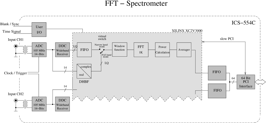
The system is configured to process two channels in parallel, each channel with a 50 MHz bandwidth. It is based on a data acquisition card ICS554C (ICS ics (2003)), consisting of two 14-bit ADCs running at 100 MHz sample rate, a Xilinx FPGA, two FIFO-buffers and a PCIbus interface (Fig. 1).
The on-board Xilinx XC2V3000 FGPA is capable of processing the signal from both ADCs in parallel to produce 2 1024 channel spectra. The digital data streams produced by both ADCs are connected to the FPGA and piped in through separated Digital Down Converters (DDC) chips which are installed to determine the bandwidth (increase the spectral resolution) of the signal and to select sub-bands. Any necessary mixing and filtering is done digitally in these DDCs. No analog elements are used and reconfigurating the sub-band and bandwidth is easily done via the PC. The DDCs are GC4016 quad receivers (Graychip gray (2000)), each one containing four identical down conversion circuits. The input data stream can be received in four separate sub-bands, each with up to 2.5 MHz bandwidth. By combining all of these, a maximum bandwidth of 10 MHz can be processed, corresponding to a spectral resolution of about 10 kHz per spectral channel. The best resolution of Hz per channel can be achieved by reducing the minimum bandwidth to 20 kHz.
2.2 Implementation
Individual cores were purchased from RF-Engines to implement the processing pipeline shown in Fig. 1. This straightforward implementation and concept makes it possible to obtain debugging information at any stage of the pipeline.
The “raw” data from the ADCs, as well as the data processed by the DDCs, are routed into the FPGA in parallel. A virtual switch has been implemented in order to select data either as Full Band (50 MHz bandwidth) from ADC (also referred to as the Distributed Halfband Filter, DHBF) or Narrow Band (10 MHz – 20 kHz bandwidth) from the DDCs. When using the DHBF, the bit stream is mixed with sine and cosine waves to shift the signal, centered symmetrically about the IF of half the bandwidth, to a signal centered at 0 Hz (see Fig. 2 (b–c)). In contrast to real-only digitization this technique yields a full Nyquist sampling, and the following pipeline FFT works with the highest efficiency on the complex data.
An additional FIFO had to be added to deal with data by the DDCs. This is because the pipeline always transfers data of exactly 2048 samples, but the data produced by the DDCs are not delivered continuously.
A window function is applied to the data first (Kaiser kaiser (1974)). This function is freely programmable via the PC without re-loading the FPGA design by means of “slow” PCIbus connection.
The central element of the whole processing pipeline is the Vectis HiSpeed 1024-point radix–2 FFT algorithm developed by RF-Engines. This pipelined FFT-core works up to 100 MHz, enabling a continuous Fourier Transformation of the input signals. The output consists of 27-bit interleaved real and imaginary signed data, which are fed into the power spectrum calculator and the following averager.
There are two possible communication channels between the FPGA and the PC: on the one hand a “slow” 8 bit PCI control bus, on the other hand the ICS554C card with two outgoing hardware FIFOs, which can transfer data via a 64–bit, 64 MHz PCI bus. This gives a maximum PCI burst data transfer speed of up to 528 MB .
The control bus is used to set window, integration time (number of samples) and observing mode, as well as a readout of data ready and status information. The FIFOs are used to transfer the Fourier transformed and pre-integrated spectra. The high speed connection is essential to keep the sub-samples integration time low, e.g. for radio frequency interference (RFI) investigations or pulsar measurements.
PC software was developed that is capable of setting control values for the window, integration time and the configuration of the DDCs. The PC is responsible for triggering the first sample and then wait for a data ready signal. The PC software then reads back the integrated spectra from 2 channels using the hardware FIFOs in FPGA and DMA mode. The data are stored as ASCII-files with an optional header.
2.3 Stability Tests


In order to quantify the stability of the spectrometer, we examined its performance when connected to a wideband noise generator. The Allan plot (Schieder schieder (1985)) generated by this exercise implies us stability times seconds (see Fig. 3). Compared to other spectrometers this is excellent and highly sufficient for astronomical applications.
The first quantitative evaluation of the IAU standard position S7 H i-line spectra (Kalberla et al. kalb82 (1982)) suggested that the new FPGA-spectrometer using samplers with 14-bit dynamics is a factor of about more sensitive than the 1024-channel autocorrelator, which uses 1-bit sampling. A few days later in a second observing run, we were able to observe S7 with a cold 21-cm receiver. We compared the FPGA-spectrometer data with the 1024- and 8192-autocorrelator (which uses 2-bit/3-level sampling) spectra observed in parallel. Our results are plotted in Fig. 4.
The sensitivity of the system, given by the standard radiometer formula
| (1) |
with for 1-bit autocorrelators, for the 2-bit/3-level autocorrelator, and for the FPGA-spectrometer (Hagen & Farley hagen (1973)), clearly indicates superior sensitivity of the FPGA-spectrometer. The fit gives us a ratio of 1.53 between the FPGA-spectrometer and the 1024 channel / 1-bit autocorrelator C values and a ratio of 1.21 between the FPGA-spectrometer and the 8192 channel autocorrelator / 2-bit, 3-level.
3 Observation


The first light observation using our FPGA-spectrometer occured on 24 August 2004. To study the quality of the H i 21-cm line spectra we chose the northern sky standard calibration source S7. For a first look, we used the whole band (50 MHz) of the FPGA-spectrometer. Fig. 5 (top) shows the recorded spectrum of the standard calibration source. We intended to use a frequency switching mode to determine the baseline of the spectrometer as accurately as possible. This was done by integrating for 30 seconds at the center-frequency (ON spectrum), shifting the frequency by tuning the receiver by 6 MHz, and integrating for an additional 30 seconds (OFF spectrum). To normalize the line emission detected by the FPGA-spectrometer, we used the S7-spectra observed in parallel with the autocorrelator spectrometer operated and, implementing standard H i data reduction procedures (Peter Kalberla, priv. comm.) determined the system temperature and evaluated the quality of the S7-calibration observation. The velocity resolution of the 50 MHz FPGA data corresponds to 10.32 . We computed the difference of the ON and OFF spectra and performed a relative calibration using a part of the baseline which is free of astronomical line emission.
Since the velocity channel width of 10.32 is much too coarse for galactic H i studies, we switched to the DDC mode, setting the initial bandwidth of 2 MHz. 88% of this bandwidth is scientifically usable because of the digital bandpass of the DDCs, which suppresses the band edges. Following the same frequency switching procedure as described above, we observed the S7-line profile with a 0.5 velocity resolution (Fig. 5 bottom). The baseline subtraction was performed as described above.
To evaluate the dynamic-range of the FPGA-spectrometer, we observed the OH maser lines of the W3OH-star forming region (Norris & Booth norris (1981)). Using a 2 MHz bandwidth, we simultaneously observed 120 K line emission at 1667 MHz and about an order of magnitude stronger line emission of the maser at 1665 MHz. Fig. 6 (top) shows these data without any baseline subtraction. All DDC spectra reveal a sinusodial baseline modulation, which is very stable in time. Accordingly we always obtain an accurate flat baseline after a simple ON-OFF subtraction as described above. Using the DDCs to increase the velocity resolution to 0.03 , we can resolve an individual line complex (Fig.6 bottom). Please note that the OH-spectra, in contrast to the S7 H i-spectra, are not normalized. It is worth noting that we do not need to change any attenuator in our setup when switching from the weak continuum S7 21-cm line observations to the OH-maser region. This is necessary when using the autocorrelator spectrometer with its limited dynamic range.
4 Conclusion
First light observations using an FPGA-spectrometer have been performed at the Effelsberg 100-m Telescope. These observations demonstrate that FPGA-spectrometers are capable of superseding current standard spectrometers with their limitations in bandwidth, number of spectral channels and dynamic range. Moreover, the sensitivity is superior to autocorrelators due to the larger number of ADC bits. Considering the high redundancy and low costs offended by commercial products, FPGA-spectrometers might well be the future in radio astronomy spectroscopy.
Acknowledgements.
We would like to acknowledge the major contribution of Ingo Krämer to overcome minor and major difficulties during the FPGA programming. The excellent cores of RF-Engines (http://www.rfel.com) allowed us to develop the FPGA-spectrometer on a time-schedule of only a few months. We would also like to thank Alexander Kraus for the rapid scheduling of the test observing time at the 100-m Telescope and Mike Bird for carefully reading the manuscript.References
- (1) GC4016 Multi-Standard Quad DDC Chip Data Sheet, 2000
- (2) Groshong, R., & Ruscak, S., “Undersampling Techniques Simplifiy Digital Radio”, Electronic Design, 1991
- (3) Hagen, J. B., Farley, D. T., 1973, Radio science, Vol 8, 775
- (4) Harris, F. J., 1978, Proc. IEEE 66(1), 51
- (5) ICS554C Operating Manual, ICS, 2003, http://www.ics-ltd.com
- (6) Kaiser, J. F., Proc. 1974, IEEE Int. Symp. on Circuits and Syst., 20
- (7) Kalberla, P.M.W., Mebold, U. & Reif, K. 1982, A&A 106, 190
- (8) Lyons, G. R., “Understanding Digital Signal Processing”, Prentice Hall NJ, 1997
- (9) Manchester, R. N., et al., 2001, MNRAS 328, 17
- (10) Norris, R.P., & Booth, R.S., 1981, MNRAS 195, 213
- (11) Schieder, et. al, 1985, in. Proc. of SPIE, Vol. 598, 189
- (12) Staveley-Smith L. et al., 1996, Proc. Astr. Soc. Aust. 13, 243