TWO-MIRROR
SCHWARZSCHILD APLANATS.
BASIC RELATIONS††thanks: Astronomy Letters, Vol. 31, No. 2, 2005,
pp. 129 –139. Translated from Pis’ma v
Astronomicheski Zhurnal, Vol. 31, No. 2, 2005, pp.
143 –153. Original Russian text © 2005 by Terebizh.
Abstract — It is shown that the theory of aplanatic two-mirror telescopes developed by Karl Schwarzschild in 1905 leads to the unified description both the prefocal and the postfocal systems. The class of surfaces in the ZEMAX optical program has been properly extended to ascertain the image quality in exact Schwarzschild aplanats. A comparison of Schwarzschild aplanats with approximate Ritchey–Chrétien and Gregory–Maksutov aplanatic telescopes reveals a noticeable advantage of the former at fast focal ratio of the system.
© 2005 MAIK “Nauka/Interperiodica”.Key words: telescopes, astronomical optics.
INTRODUCTION
In a series of papers written a century ago, Karl Schwarzschild laid the foundations of the modern aberration theory of optical systems, including telescopes (see Born and Wolf 1999, Ch. 5; Wilson 1996, 3.2). The last section in part II of this series (Schwarzschild 1905) is devoted to seeking for an aplanatic two-mirror telescope, i.e., a system in which both spherical aberration and coma were rigorously corrected near to an optical axis. Schwarzschild managed to derive closed analytical formulas that described the shape of the mirror surfaces in such a telescope. Since he was primarily interested in fast systems (the photographic emulsions were then slow), a telescope with a primary mirror of moderate focal ratio and a concave secondary mirror that brought the total focal ratio of the telescope to was considered as an example (see Fig. 5 below). Subsequently, Born and Wolf (1999, §4.10.2) gave a general formulation of the problem of the simultaneous correction of spherical aberration and coma in an arbitrary optical system. Grazing-incidence Schwarzschild telescopes designed for X-ray observations were considered by Popov (1980, 1988)111After the completion of this paper, we learned about the papers by Lynden-Bell (2002) and Willstrop and Lynden-Bell (2003) devoted to two-mirror aplanats. Having only part X of the fundamental study by Schwarzschild (1905) at their disposal, these authors have repeated in a different form some of the results contained in part II of that study..
Quite possible, the context in which Schwarzschild discussed the problem and the example mentioned above have spawned the widely held view that Schwarzschild’s theory is applicable only to prefocal reducing systems (see the next section for an explanation of the terms). Meanwhile, this theory covers not only all prefocal systems, including Cassegrain telescopes, but also postfocal Gregorian systems. Moreover, Schwarzschild’s formulas that define the mirror surfaces in an aplanatic telescope can be brought to a form that is valid for an arbitrary two-mirror system.
Since the analytical description of the shape of the mirror surfaces in exact aplanats is rather complex in form, the image quality provided by these telescopes has remained not cleared up until now. Only the approximations of the surfaces by conic sections admissible for systems with slow focal ratios were considered. The expansions that emerge in this case were found by Schwarzschild (1905) himself. Subsequently, Chrétien (1922) and Maksutov (1932) concretized these expansions for Cassegrain and Gregorian systems, respectively, which gave rise to the telescopes aplanatic in the third order of the aberration theory. Most of the modern major instruments belong to this class. The merits of these systems and the discovery of a fast wide-field camera by Bernhard Schmidt (1930) were responsible for the prolonged lack of interest in Schwarzschild’s exact theory.
This situation was explicable as long as the diameter of Schmidt telescopes corresponded to the needs and technology capabilities of the time. At present, one can point out several problems of observational astronomy in connection with which it would be interesting to return to Schwarzschild’s theory and ascertain the image quality achievable with exact aplanats. In particular, one of the most important problems is to carry out deep sky surveys using telescopes with an effective aperture of 4–7 m and a field of view. This will allow to study the evolutionary cosmological models and to follow the changes in the positions and brightness of faint objects on a time scale of the order of a day within the entire celestial sphere. An example of another vital problem involves far-ultraviolet and X-ray observations from spaceborne platforms, suggesting the use of telescopes with a minimum number of reflective surfaces. As regards the technology capabilities, in producing complex aspherical surfaces with a diameter of the order of several meters, an accuracy that ensures the diffraction-limited image quality has been achieved in recent years.
In this paper, we represent Schwarzschild’s formulas in a form that is valid for arbitrary two-mirror aplanatic systems. Subsequently, we analyze the image quality in aplanats calculated by extending the class of surfaces in the standard ZEMAX optical program 222ZEMAX Development Corporation, USA.. We show that exact Schwarzschild aplanats with a fast focal ratio provide much better images than Ritchey–Chrétien and Gregory–Maksutov systems, which are aplanatic only in the third order of the aberration theory.
FIRST-ORDER CHARACTERISTICS
Depending on whether the secondary mirror precedes or succeeds the focus of the primary mirror, the two-mirror telescopes are divided into two major classes: prefocal and postfocal systems (Maksutov 1932, 1946; Michelson 1976). The equivalent focal length is positive for prefocal systems, and is negative for postfocal systems. Each of the major classes includes focal reducing and lengthening systems; is smaller and larger in absolute value than the focal length of the primary mirror for the former and the latter, respectively (we assume that ).

Basic notation for a Cassegrain system as an example.
Let be the difference between the axial coordinates of the secondary and primary mirror vertices; be the back focal length of the system; be the height of the ray incident on the primary mirror parallel to the optical axis; be the height of this ray on the secondary mirror; and are the sags of the primary and secondary mirrors corresponding to this ray; and is the angle between the ray emergent from the system and its optical axis. The notation used for a Cassegrain system is explained in Fig. 1. We assume that the entrance pupil of the telescope is located on the primary mirror, is always negative, and are positive, the signs of and are identical to those of the vertex radii of curvature and for the corresponding mirrors, and are positive for a prefocal system and negative for a postfocal system. Since the system is axially symmetric, to describe the shape of the surfaces, it will suffice to consider only their meridional section by the plane.
We choose the following four parameters as the specified characteristics of the system:
-
–
the diameter of the primary mirror ,
-
–
the equivalent focal length of the telescope ,
-
–
the relative value of the back focal length ,
-
–
the quantity that is the reciprocal of the magnification on the secondary mirror.
To avoid misunderstandings, the classification of two-mirror telescopes used here is summarized in the Table 1. The parameters and can take on any values from to . For slow telescopes, is approximately equal to the linear central obscuration coefficient by the secondary mirror. We are mainly interested in values of : it is in this range the promising telescopes should be sought.
| Table 1. Types of two-mirror telescopes | |||
|---|---|---|---|
| System | Lenthening | Shortening | |
| Prefocal | Cassegrain | Schwarzschild | |
| Postfocal | Gregory | ||
Evidently, the focal ratio of the telescope is , and the remaining first-order characteristics of all the systems under consideration may be represented in terms of the initial parameters as
For the subsequent analysis, it is convenient to introduce the special designation
so .
SCHWARZSCHILD’s FORMULAS
A necessary condition for the absence of coma is the satisfaction of the Abbe sine condition in the system,
for all of the ray heights and aperture angles . Schwarzschild managed to rigorously combine the sine condition and the equation for the ray passage in the system. The original calculations apply only to a reducing prefocal system for , but they are so general in nature that can also be performed for systems of other types with minor modifications. Since these calculations are very cumbersome, we will not present them here, but only write out the final formulas in a form that is valid for an arbitrary two-mirror system.
The sought relations can be written in parametric form; they relate the ordinates of the light ray (, ) at the points of its intersection with the mirror surfaces and the mirror sags (, ) corresponding to these points to the free parameter
Equation (3) and the condition yield the maximum aperture angle:
and substituting this value into (4) yields
Usually, is small; even for a fast system with a focal ratio of we have .
Let us also define the index
Then, the formulas that specify the primary mirror profile can then be written as
The analogous relations for the secondary mirror are
where the auxiliary function
Note that the results for can be obtained both by repeating calculations similar to Schwarzschild’s original calculations and by passing to the limit . According to (2), in the case under consideration, and formulas (1) take the form
Thus, assigning values from the interval to the free parameter , we find the profile of the mirror surfaces from formulas (8)–(10) that ensure the absence of spherical aberration and coma in an arbitrary two-mirror telescope.
SLOW SYSTEMS
According to (6), the upper boundary of the free parameter is less than at and, at an even slower focal ratio, is
For this case, Schwarzschild (1905) expanded the exact formulas in power series of the normalized ray heights and , the first terms of which in our notation are
The expansions are also valid for .
The sag of an arbitrary conic section is known to be
where is the dimensionless radius of curvature at the vertex, and is the surface eccentricity. Hence, one can easily obtain the expansion
Its comparison with (12) and (13) allows the approximation of exact aplanatic surfaces by conicoids for slow systems to be elucidated.
For the primary mirror, the first two expansion terms give the following expressions for the radius of curvature and the square of the eccentricity:
Give the definition of the constant in (2), we see that the former expression is identical to that in (1), while it follows from the latter expression that
Just as above, we obtain for the secondary mirror:
The expression for is identical to that in (1), while the square of the eccentricity of the secondary mirror expressed in terms of the basic variables can be written as
Equations (17) and (19) form the basis for the theory of systems aplanatic in the third order of the aberration theory (see, e.g., Schroeder 2000, §6.2.b). For clarity, Fig. 2 gives a graphical representation of these expressions that is essentially identical to that in the book by Maksutov (1946, §21). An afocal Mersenne system of two paraboloids with coincident foci corresponds to . For , Eqs. (17) and (19) describe a Ritchey–Chrétien system. The case of corresponds to the so-called ring telescope with a planoid secondary mirror (Maksutov 1932; Churilovskii 1958; Landi Dessy 1968). The domain corresponds to the family of reducing Schwarzschild telescopes aplanatic in the third-order approximation. In the entire domain , the primary mirror is a hyperboloid, while the secondary mirror is a hyperboloid in a lengthening aplanat and changes its shape for reducing systems from an oblate ellipsoid333This is the region of the ellipsoidal surface around the point of its intersection with the minor axis; previously, an oblate ellipsoid was commonly called an oblate spheroid. to a hyperboloid, passing through a sphere and a prolate ellipsoid. The domain corresponds to the aplanatic version of the Gregory system. Here, the secondary mirror remains a prolate ellipsoid, while the primary mirror changes its shape from a prolate to an oblate ellipsoid, also passing through a sphere.
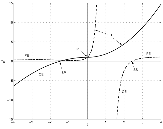
Squares of the eccentricities of the primary (solid line) and
secondary (dashed line) mirrors versus in approximate aplanats at :
P – paraboloid, H – hyperboloid, PE – prolate ellipsoid, OE –
oblate ellipsoid, SP – spherical primary mirror, SS – spherical secondary
mirror.
We emphasize that Fig. 2 describes slow systems in which only the third-order aberrations were corrected. Therefore, it gives only a rough idea of the family of exact aplanatic surfaces.
SCHWARZSCHILD SURFACES IN THE
ZEMAX PROGRAM
Ascertaining the image quality in exact Schwarzschild aplanats requires either developing a special program for calculating the ray path in such systems or extending the class of surfaces in one of the existing optical programs. We chose the second way, especially since the powerful ZEMAX optical program allows it to be implemented with relative ease. This requires writing additional programs in the C/C language in which the new surfaces (8)–(10) and the optics based on them are described and then compiling these programs and dynamically linking them with the main program. Thus, we can use the extensive set of tools for studying the properties of optical systems provided by ZEMAX.
In this way, we created the files ksp.dll and kss.dll (from Karl Schwarzschild primary/secondary) that define, respectively, the primary and secondary mirrors of an arbitrary aplanat. The quantities defined in the section entitled “First-Order Characteristics” should be specified as additional parameters when calling a surface.
EXAMPLES OF FAST APLANATS
An analysis of several model systems indicates that Ritchey–Chrétien and Gregory–Maksutov systems yield a satisfactory approximation to exact aplanatic systems for of or larger. Volume of this publication does not allow us to illustrate the change in image quality as the focal ratio of the system becomes faster; here, we restrict our analysis to several examples. The optical telescope layouts considered below should give a general idea of the quality of the images obtained with exact aplanats.
We characterize the image quality by the quantity , the diameter of the circle within which 80% of the energy is concentrated in the diffraction image of a point source. Denote the diameter of the field of view in which does not exceed one arcsecond by .
The astigmatism and the field curvature remain uncorrected in aplanatic systems. Usually, these aberrations in mirror telescopes are removed by inserting lens correctors. A preliminary analysis shows that a simple corrector of three lenses with spherical surfaces inserted in a lengthening Schwarzschild aplanat provides flat field of view about in diameter (see section “Including Schwarzschild Aplanats in Complex Systems” below). We are going to systematically study the correctors in Schwarzschild aplanats later.
The Cassegrain System
Figure 3 shows the optical layout of the SA-01 telescope with an aperture diameter of 1 m and a focal ratio of . We chose and for the remaining parameters, so the magnification on the secondary mirror is . The focal ratio for the primary mirror is , which is achievable at the present state of the art.

Optical layout of the SA-01 telescope with a focal ratio of .

Spot diagrams for the SA-01 telescope in the field of view
(the wavelength is 0.5 m). The root-mean-square (RMS)
and geometrical (GEO) image radii as well as the diameter of the circle
corresponding to are given in micrometers.

Optical layout of the SA-02 telescope with a focal ratio of .

Spot diagrams for the SA-02 telescope in the field of view
(the wavelength is 0.5 m). The RMS and geometrical (GEO)
image radii as well as the diameter of the circle corresponding to are
given in micrometers.

Three-lens corrector to the SA-01 telescope.

Spot diagrams for the SA-01 telescope with the corrector shown in Fig. 7. The diameter of the flat field of view is ; polychromatic light with wavelengths of 0.4–1.0 m is considered. The RMS and geometrical (GEO) image radii as well as the diameter of the circle corresponding to are given in micrometers.