Further author information: (Send correspondence to A.P.)
A.P.: E-mail: pisa@fe.infn.it, Telephone: +39 0532 974215
Feasibility study of a Laue lens for hard X–rays for space astronomy
Abstract
We report on the feasibility study of a Laue lens for hard X-rays ( keV) based on mosaic crystals, for astrophysical applications. In particular we discuss the scientific motivations, its functioning principle, the procedure followed to select the suitable crystal materials, the criteria adopted to establish crystal dimensions and their distribution on the lens in order to obtain the best lens focusing capabilities, and the criteria for optimizing the lens effective area in a given passband. We also discuss the effects of misalignments of the crystal tiles due to unavoidable mechanical errors in assembling the lens. A software was developed to face all these topics and to evaluate the expected lens performance.
keywords:
hard X-ray astronomy, hard X-ray optics, crystal diffraction1 Scientific motivations
The role of hard X-ray astronomy ( keV) is now widely recognized. The numerous results obtained with the most recent satellite missions (BeppoSAX, Rossi–XTE) on many classes of X-ray celestial sources have demonstrated the importance of the broad band ( keV) spectroscopy in order to derive an unbiased picture of the celestial source physics, like to establish the source geometry, the physical phenomena occurring in the emission region, the radiation production mechanisms, an unbiased separation of the contribution of thermal emission phenomena from the phenomena due to the presence of high energy plasmas (thermal or not thermal) and/or magnetic fields and/or source rotation.
In spite of the excellent performance of the high energy instrument PDS (Phoswich Detection System) aboard BeppoSAX [1], the most sensitive instrument ever flown in the 15-200 keV energy band, even in the case of the strongest Galactic (e.g., Cyg X-1 in soft state, Her X-1) and extragalactic (e.g., 3C373, MKN 3) X-ray sources, the statistical quality of the measured spectra becomes poor in the highest part of the instrument passband ( keV). Thus the development of focusing optics in this band and, more generally, in the entire passband covered by the BSAX/PDS and possibly beyond it, is of key importance to overcome the limitations of the direct viewing telescopes (with or without masks) and to allow the study of the high energy spectra of the celestial sources with the same detail which is achieved at lower energies ( keV), where focusing optics are available.
In fact, X–ray mirrors, based on the external reflections with very high focal lengths ( m), or ‘supermirrors’ based on Bragg diffraction from multilayers of bi-strates made of high and low Z materials (e.g., Joensen et al. [2]), can overcome the sensitivity problem up to about 70 keV. For higher energy photons, an efficient focusing is a much more challenging task.
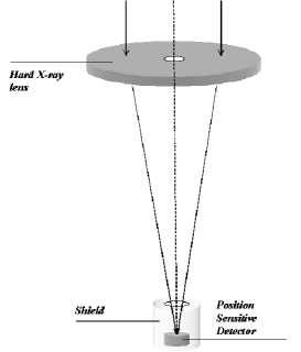
Goal of our project is the development of a focusing telescope which efficiently focus hard X-/gamma-rays in a broad continuous band, from 70 keV to keV, by exploiting the Bragg diffraction from mosaic crystals in Laue configuration.
2 Laue lens crystal requirements
The X-ray diffraction from crystals in reflection (Bragg geometry) or transmission (Laue geometry) configurations is well known (e.g., James [3]). The first step of our feasibility study we are reporting on is to establish the lens physical properties, like the most suitable crystal materials, their sizes (cross section, thickness), and their orientation in the lens, which maximize the lens performance with sustainable costs.
In order to better understand the problematics of a Laue lens, we first summarize basics of crystal diffraction and properties of mosaic crystals.
2.1 Basics of the crystal diffraction theory
As it is well known, the X-ray diffraction from crystals is based on the two equivalent equations:
| (1) |
| (2) |
the first due to M. von Laue,[4] and the second due to W.H. and W.L. Bragg.[5]
In the Laue equation (1), and are the wave vectors of the incident and the diffracted beams and is the reciprocal lattice vector. In the Bragg law (2), is the distance between the lattice planes with Miller indices , is the scattering angle for diffraction (the Bragg angle), is the diffraction order and is the wavelength of the photon. The energy of the photon is related to through the relation , in which keVÅ. The two equations are completely equivalent and provide the same information: for example, the angle between the two wave vectors and is exactly twice the Bragg angle and the reciprocal lattice vector is perpendicular to the planes and its module has magnitude .
According to the above equations and depending from the crystal structure, a parallel polychromatic photon beam will be splitted in several monochromatic beams with directions depending on the photon energies present in the beam and on crystal planes which diffract photons. In fact, due to crystal defects, ion thermal motion and finite size of the sample, the diffracted beam is not monochromatic but shows a small spread in energy with an intensity peak centered around the energy which corresponds to through the Bragg law.
We have to face a couple of important problems for getting the Laue lens for our applications: a geometrical problem, and an efficiency problem. The first concerns the need of focusing photons into a very small area, the second is the need of maximizing the reflection efficiency in a broad band. A nearly–perfect crystal, could solve the first problem through a proper geometry of the crystal shape, but not the second one (the high efficiency is limited to a very narrow band). The best compromise is achieved by using imperfect crystals with a suitable spread of the photon energies which can be reflected. The best crystals which can satisfy our requirements are the mosaic crystals, as we demonstrate below.
2.2 Mosaic crystals
Mosaic crystals are made of many microscopic perfect crystals (crystallites) with their lattice planes slightly misaligned with each other around a mean direction, the one corresponding to a reciprocal lattice vector . In the configuration assumed, the mean lattice plane is normal to the mosaic crystal surface. The distribution function of the crystallite misalignments from the mean direction can be approximated by a Gaussian function:
| (3) |
where is the magnitude of the angular deviation from the mean. The Full Width at Half Maximum (FWHM) of the Gaussian function defines the mosaic spread of a mosaic crystal. The quantity is the probability of finding crystallites with planes misaligned by an angle in the range from the mean direction.
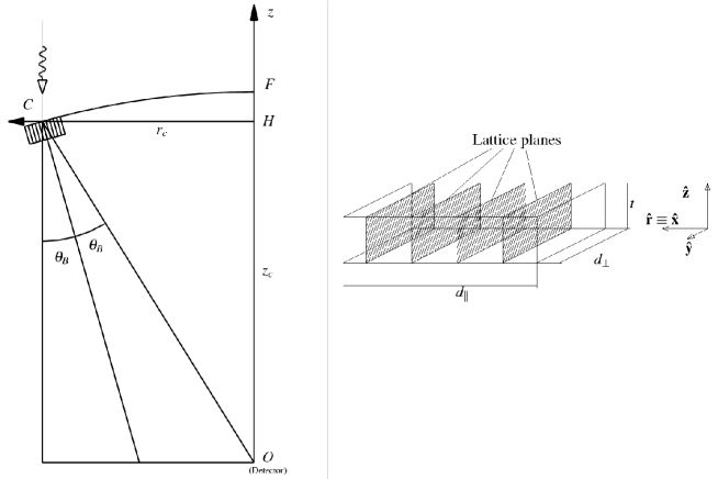
For the Laue geometry and plane parallel plates, with diffracting planes perpendicular to the plates (see the right side of Fig. 4), the intensity of the diffracted beam is given by the following equation [6]:
| (4) |
where is the intensity of the incident beam, is the absorption coefficient per unit of length corresponding to that energy, is the cosine of the angle between the direction of the photons and the normal to the crystal surface, is the thickness of the mosaic crystal and is:
| (5) |
where
| (6) |
in which is the classical electron radius, is the structure factor, is the volume of the crystal unit cell, is the wavelength and is the Bragg angle for that particular energy.
The quantity is known as the secondary extinction coefficient and is the distance travelled by the direct beam inside the crystal.
From Eq. (4) it is possible to see that, for fixed values of , the value of is monotonically increasing with and monotonically decreasing with ; thus to increase the diffracted beam, it is necessary to adopt materials with low values for and great values for . The best thickness, , that maximizes the value of can be obtained equating the first derivative of (4) with respect to to zero. The result of this operation is:
| (7) |
The maximum achievable value for is , that is a limiting value obtainable in the ideal case of zero absorption and infinite secondary extinction. Using the Eq. (4), it is possible to deduce some important and useful properties of the diffracted photon beam.
2.3 Properties of the photon beam diffracted by mosaic crystals
The total diffracted intensity of a parallel photon beam increases with the mosaic spread . However also its divergence increases with . As a consequence, a polychromatic parallel beam, after its reflection by a mosaic crystal not only has a different energy distribution but also a different size. We have determined the spread of a photon beam diffracted by a mosaic crystal in a plane perpendicular to the incident beam direction. Assuming a crystal with plane parallel plates and sizes shown in Fig. 4, with mean lattice plane perpendicular to the crystal surface and misalignment distribution of the microcrystals (see Eq. 3) along all azimuth directions, for a uniform parallel photon beam incident on the crystal, which is large enough to intercept the whole of it with incidence angle (grazing angle from the mean lattice plane), the diffracted beam in a plane perpendicular to the incident beam has dimensions larger than the crystal cross section. The maximum enlargement is along the direction perpendicular to the mean lattice plane. In this direction the linear enlargement (where is 98% of the reflected power) is , where is the distance from the crystal, while in the perpendicular direction it is . Given the small Bragg angles for hard X-rays ( keV), the latter quantity is a factor 100 lower than the former.
As far as the energy distribution of the diffracted beam is concerned, assuming a uniform polichromatic beam, by means of the Bragg law (see Eq. 2), we get that the energy range diffracted by the mosaic crystal along the direction normal to that of the mean lattice plane is approximately given by , where , and , in which is the Bragg energy corresponding to the incidence angle . Thus the energy spread corresponding to the mosaic spread is . Given that for hard X–rays, , the energy spread is proportional to .
2.4 Crystal material choice
From the formulae given in Section 2.2, the materials for a Laue lens should be chosen according to the following guidelines: low and high to maximize the crystal reflectivity, low to get large reflection angles, and thus high lens effective area (see Section 5), in the lens energy passband. However mosaic spread has to be chosen with care. Indeed, on one side a higher value gives a higher crystal reflectivity, on the other side it degrades the focusing capabilities of the lens. Apart from that the prerequisite for the crystal material is either that it is already available on the market with the required mosaic properties or that its development with the required mosaic properties is feasible.
Thus we started our feasibility study assuming mosaic crystal materials that satisfy the the above prerequisite. These include Highly Oriented Pyrolitic Graphite (HOPG), Germanium and Copper. The lattice structure of HOPG (with Miller indices 002) is hexagonal with spacing Å and that of Cu (111) and Ge (111) is Face Centered Cubic (FCC) with Å for Copper and Å for Germanium.
HOPG is available since a long time, but its mosaic spread is , while Ge (111) can be obtained in mosaic configuration with a spread , and mosaic crystals of Cu (111) can be now obtained with a mosaic spread between 1 and 10 arcmin. Given their low mosaic spread, the last two materials show better focusing capabilities. Instead HOPG appears less suitable, not only for its larger mosaic spread, but also for an additional drawback for its use in transmission configuration. Indeed, given that it is produced in plates with a maximum thickness of a few millimeters and the (002) planes are parallel to the plates, its use in Laue configuration with lattice planes normal to the crystal cross section, requires several plates to be stacked together, a task which we have experimented and found to introduce further mosaic spread. In spite of these technological problems, we have compared the expected performance of all these crystals. The energy dependence of their and in the 60–400 keV band is shown in Fig. 1, in which for we assumed arcmin and . The energy behavior of the expected peak reflectivity for arcmin, a crystal thickness of 0.5 mm for HOPG and 0.2 mm for Cu (111) and Ge (111), is shown in Fig. 2. As can be seen, Cu(111) shows the best peak reflectivity in the 100–400 keV energy band.
 |
 |
 |
3 Lens geometry and its main properties
3.1 Lens geometry
For a parallel photon beam, as that coming from a celestial X–ray source, among the possible focusing geometries of a Laue lens made of mosaic crystals in transmission configuration with mean lattice plane perpendicular to the crystal surface, the paraboloids of revolution or the spherical surfaces appear the simplest. They satisfy the projective transformations, as required for a perfect imaging [8]. The crystals should be curved according to the chosen geometry. In the case of flat crystals, the best approximation of the geometry is obtained by using small crystals. For high focal lengths ( m), as requested in the case of hard X–rays, the two geometries, paraboloid of revolution or sphere, are practically undistinguishable. In our feasibility study we have assumed a spherical shape. A sketch of a Laue lens is shown in Fig. 3. It has the appearance of a spherical corona, with inner and outer radii which depend on the energy bandwidth of the lens (see below). Assuming a paraboloidal shape, assuming a spherical geometry the image of a source at infinity is at half of the sphere radius. Spherical geometries are the most used also to focus diverging X–ray beams [7].
 |
 |
3.2 Crystal orientation
Given that flat crystals are more feasible, we have assumed plane parallel crystal tiles of sizes , and (see right panel of Fig. 4), where is the length of the crystal side parallel to the axis of the mean lattice plane, is the length of the crystal side perpendicular to , and is the crystal thickness. The lenght of the crystal sides and should be as small as possible in order to better approximize the lens shape. In fact their sizes are a compromise between the focusing capabilities of the lens and number of crystal tiles required.
Before discussing the arrangement of the single crystals in the lens we introduce a reference frame that analytically defines the position and orientation of each crystal (see Fig. 4). Given the spherical shape of the lens, a cylindrical reference frame, with the axis coincident with the lens axis and its origin in lens focus, it is natural choice. In this reference frame the position of a generic crystal is singled out by means of three coordinates: the coordinates of the crystal center , where is the distance from the lens axis and is the distance from the focal plane, and the rotation angle of the crystal around the axis (angle between the crystal axis and the axis). To correctly focus photons of energy centroid , it is needed that (Bragg angle corresponding to , see Fig. 4), and that
| (8) |
| (9) |
where is the focal distance of the lens (i.e., half radius of the spherical corona radius). From the previous equations, the rotation angle, and so the energy of the diffracted photons, depend on the crystal position through the relation .
 |
3.3 Lens energy passband and projected area
The nominal energy passband of the lens is related to the values of the outer and inner radii and , respectively, of the spherical corona, through Eq. (9) and the Bragg law. We get
| (10) |
and
| (11) |
One of the key parameters of a Laue lens is the projected area of the lens in the focal plane. If the entire spherical corona was entirely covered with crystals, the projected area would be that of circular corona, . This area can be maximized in two ways: or increasing the lens focal length, or, for a given , using materials with lower . It can be easily shown that . We notice however that higher focal lengths require smaller spreads of the mosaic crystals to avoid a larger dispersion of the diffracted photons in the focal plane (Point Spread Function, PSF). The PSF linearly increases with F.
For a given and lens energy passband, increases with , and thus, through Eq. (2), the lens projected area can be increased using materials with lower . In principle could be lowered even using highest diffraction orders, but this would imply lower diffraction efficiency, since (see Eq. 6), through , decreases with the diffraction order.
If the spherical corona cannot be completely covered with crystals (this is the case in which flat crystal tiles are available), it is useful define a filling factor f, which gives the ratio , where is the lens area covered with crystals. It can be easily shown that, for a given lens energy passband, increases with the ratio between the focal length and the crystal tiles dimensions and thus using a greater number of tiles, which allows to obtain a better approximation of the spherical corona.
3.4 Arrangement of the crystals in the lens
While the lens energy passband, for a given , depends on the inner and outer radii of the spherical corona, it can be shown that the lens effective area (defined as the projected area of the lens in the focal plane times the reflection efficency) depends on energy in a way which is related to the arrangement of the crystal tiles in the lens.
In order to get an energy behavior of the lens effective area as smooth as possible, we followed the suggestion by Lund[9] of arranging the crystal tiles according an Archimedes spiral:
| (12) |
where is the distance of the crystal from the lens axis, is the length of the crystal tile along the lens radial direction (see Fig. 4), is the extra-space needed for its accommodation, and is the azimuthal angle of the crystal center , i.e. the angle between the radial vector of the crystal and the radial vector of first crystal positioned in the lens. The coordinate is set according to the already seen relation, Eq. (8).
So, for a given , the crystals are positioned with the following procedure: once the Bragg angle is established on the basis of the desired high energy threshold of the lens (see Eq. 11), the first crystal is positioned with its center at the coordinates , where and , and azimuthal angle 0 (arbitrary position). Then, the coordinates of the successive crystal are determined by increasing the angular coordinate by :
| (13) |
that guarantees the needed room between contiguous crystal tiles.
Once is determined from Eq. 13, we can use Eq. (12) to obtain , and then the Bragg angle and the distance of the crystal from the focal plane.
Starting from the innermost crystal, all the other crystals are recursively positioned in the lens following the above procedure until the angle of the last positioned crystal tile does not achieve a value corresponding to the low nominal energy threshold of the lens (see Eq. 10).
3.5 Crystal positioning accuracy
One of the main tasks to be faced in the integration of many (hundreds to thousands) mosaic crystals for a Laue lens is the accuracy in their orientation. Indeed this is crucial to reflect photons from the numerous crystal in the same focal plane position. The maximum error in the nominal value of should be a fraction of the spread of the crystals. This angular error is due to the uncertainty in the knowledge of the crystal optical axis and to the tolerance in the machining of the lens support. An error in the orientation of a crystal produces a linear displacement of the focal plane centroid of the crystal PSF by .
4 Developed software
For our feasibility study, we developed a software code (SWC) which analytically describes the lens geometry, its focal length, the mosaic crystal properties, the crystal sizes and their nominal orientation, the shape and size of the expected photon spot in the focal plane due to a paraxial beam of incident photons, the intensity of the diffracted beam produced by all crystals, the effect of misalignment of the mosaic crystals in the lens. All the lens parameters and crystal properties can be set at the time of run of the SWC or before according to our needs. For each set of given parameters, the SWC first computes the arrangement of the crystal tiles and then the expected effective area of the lens as a function of energy for on-axis incident photons.
The initial development of the SWC was done using the proprietary programming language rsi-IDL, but we are porting it to the Python programming language. We decided to port the SWC because Python is an open source highly object oriented program language with a plenty of scientific libraries, and it is largely used by the scientific community.
Usually the IDL software is used via a macro of commands which contains the complete set of instructions to do all the basic calculations and to give an initial output which is elaborated again through Python scripts.
| Material | Copper |
|---|---|
| Miller Indices | (111) |
| Energy Band | 60–200 keV |
| Focal Length | 300 cm |
| Tile Dimensions | cm3 |
| Mosaic Spread (FWHM) | 5 arcmin |
| Number of Tiles | 2368 |
| Inner/Outer Radius | 8.92/29.7 cm |
| Filling Factor | 0.94 |
| (cm) | Tiles Number | Weight (kg) | (cm) | (cm) | Filling Factor |
|---|---|---|---|---|---|
| 200 | 1038 | 2.78 | 5.95 | 19.8 | 0.926 |
| 300 | 2368 | 6.34 | 8.92 | 29.7 | 0.939 |
| 400 | 4238 | 11.3 | 11.9 | 39.7 | 0.940 |
5 Expected performance results
We report here a few relevant results of our feasibility study. We have assumed, as a reference, a spherical lens with parameters summarized in Table 1. It makes use of flat mosaic crystals of Cu (111) with a cross section of 10x10 mm2 and mean lattice plane perpendicular to the cross section. The nominal energy band of the lens is assumed to be 60 to 200 keV. We have computed the behavior of lens effective area with energy for different values of the focal length, the crystal thickness, the crystal mosaic spread and the uncertainty in the orientation of the crystals. The results are shown in Fig. 5. For the uncertainty in the orientation of the crystal we have assumed a Gaussian distribution with a FWHM of 12 arcmin.
In Table 2 we show the dependence of the crystal tiles number, lens crystal weight, inner and outer lens radii and filling factor as a function of the focal length, for three different values of (200, 300, 400 cm).
As can be seen from Fig. 5 (panel D), the effect of the crystal misorientation does not significantly influence the effective area. However it has a strong impact on the lens PSF and thus on the lens focusing factor given by , where is the detection area which collects the fraction of reflected photons, and is its efficiency. The focusing factor is a key parameter of the lens: its flux sensitivity depends on . In Fig. 6 we show the focusing factor for the reference lens configuration with parameters given in Table 1 for a nominal orientation of the crystal tiles in the lens, and for crystal orientations which are distributed around the nominal values according to a Gaussian function with a FWHM of 12 arcmin. The detector area has been chosen in order to get the maximum : in the first case cm2 with a collection fraction ranging from 0.60 to 0.74, while in the latter case cm2 with from 0.48 to 0.60. As can be seen, a sensitive reduction of the focusing factor is apparent when the crystals are not correctly oriented in the lens.
a |
b |
c |
d |
 |
6 Prospects
The results obtained by our feasibility study are very promising for the prospects of the hard X–ray astronomical observations ( keV). The Laue lenses appear to be the most promising focusing optics to overcome the sensitivity limitations of the current hard X–ray instruments. A key advantage of the Laue lenses is their very low weight (see Table 2), much lower than the multilayer optics now under development for efficiently focusing photons with energies below 70 keV.
The next step of our project is the development of a lens demonstration model in which we get ready the lens crystal assembling technique. Soon after we intend to develop a prototype model to be tested also in a balloon flight.
We have proposed to use Laue lenses for a high energy experiment aboard a long duration balloon flight at 3 mbar of residual atmospheric pressure. However the best exploitation of the Laue lenses is in telescopes aboard satellite missions in which high focal lengths are possible. The use of satellite formations, with a satellite with aboard the lenses and a slave satellite at a distance of tens of meters with aboard the focal plane detectors should be ideal for exploiting the capabilities of the Laue lenses. Such satellite formations are included in the strategic program of ESA.
Acknowledgements.
This research is supported by the Italian Space Agency ASI. We wish to thank Niels Lund for very useful discussions.References
- [1] F. Frontera et al., “The high energy instrument PDS on-board the BeppoSAX X–ray astronomy satellite”, Astron. Astrophys. Suppl. Ser. 122, pp. 357–369, 1997.
- [2] Joensen, K.D. et al. “Multilayered supermirror structures for hard X–ray synchrotron and astrophysics instrumentation”, Proc. SPIE, 2011, pp. 360–372, 1993.
- [3] R. W. James, The Optical Principles of the Diffraction of X–rays, Ox Bow Press, Woodbridge, Connecticut, 1982.
- [4] von Laue, M. et al. , Munchener Sitzungsberichte, 363, 1912.
- [5] Bragg, W. H et Bragg, W. L., Proc. Roy. Soc. London, 88, 428, 1913.
- [6] W. H. Zachariasen, Theory of X-Ray Diffraction in Crystals, Dover Pubblications, Inc., New York, N. J., 1994.
- [7] B. D. Cullity, X-Ray Diffraction, Addison-Wesley, 1978.
- [8] M. Born, E. Wolf Principles of Optics, Pergamon Press, 1975.
- [9] N. Lund, “A Study of Focusing Telescopes for Soft Gamma Rays,” Exp. Astr. 2 pp. 259–273, 1992.