A model for the challenging “bi-drifting” phenomenon in PSR J0815+09
Abstract
A new drifting pulsar, PSR J0815+09, was discovered in the Arecibo drift-scan searches (McLaughlin et al., 2004). An intriguing feature of this source is that within the four pulse components in the integrated pulse profile, the sub-pulse drifting direction in the two leading components is opposite from that in the two trailing components. In view that the leading theoretical model (Ruderman & Sutherland, 1975) for pulsar sub-pulse drifting can only interpret one-direction sub-pulse drifting, the observed bi-drifting phenomenon from PSR J0815+09 poses a great challenge to the pulsar theory. The inner annular gap (IAG), a new type of inner particle accelerator, was recently proposed to explain both -ray and radio emission from pulsars (Qiao et al., 2004). Here we show that the coexistence of the IAG and the conventional inner core gap (ICG) offers a natural interpretation to the bi-drifting phenomenon. In particular, the peculiar drifting behavior in PSR J0815+09 can be reproduced within the inverse Compton scattering (ICS) model for pulsar radio emission.
1 Introduction
The sub-pulse drifting phenomenon observed in many pulsars has been widely regarded as a powerful tool to probe the pulsar inner magnetospheric structure and radiation mechanism (Ruderman & Sutherland 1975, hereafter RS; Gil, Melikidze & Geppert 2003). It may be linked to the physical properties of the surface of pulsars (RS75), shedding light on the nature of pulsars, e.g. whether they are normal neutron stars or bare strange stars (Xu, Qiao & Zhang 1999).
In the classical drifting model, sub-pulse patterns are manifestations of some sparks passing along a ring (“carousel”) in the polar cap region circulating the magnetic axis (RS75). This interpretation is supported by detailed analysis of drifting data (Deshpande & Rankin, 1999, 2001; Asgekar & Deshpande, 2001; Gil & Sendyk, 2003). The RS model is the leading model to interpret the observations quantitatively. More detailed analysis revealed that the circulation speed in a pure vacuum gap is too high when compared with the observations (Gil et al., 2003). Such a discrepancy may be resolved through introducing partial screening of the gap electric field so that the inner gap is not purely vacuum (Gil et al., 2003; Cheng & Ruderman, 1980; Usov & Melrose, 1995). These models are successuful to interpret many observations, including time variations of the drift rate and changes of the apparent drift direction (Gil et al., 2003).
Recently, a new drifting pulsar, PSR J0815+09, was discovered in the Arecibo drift-scan searches (McLaughlin et al., 2004). An intriguing feature of this source is that within the four pulse components in the integrated pulse profile, the sub-pulse drifting direction in the two leading components is opposite from the one in the two trailing components. We call this “bi-direction drifting” or “bi-drifting” phenomenon. This phenomenon poses a great challenge to the RS model and its variants, since in all these models, the drifting direction in different spark-rings is expected to be the same. Recently, Qiao et al. (2004) suggested that an inner annular gap (IAG) likely coexists with the conventional inner core gap (ICG) in pulsars (especially when pulsars are bare strange stars), and proposed a phenomenological model to illustrate the origin of the -ray and radio radiation from pulsars. In this paper, we propose that the bi-drifting phenomenon is a natural consequence of the coexistence of the IAG and the ICG. Furthermore, the complicated drifting patterns in PSR J0815+09 could be reproduced if the pulsar radio emission is dominantly generated through coherent inverse Compton scattering (ICS) processes (Qiao & Lin, 1998; Xu et al., 2000; Qiao et al., 2001).
In §2, we introduce both the ICG and the IAG in pulsars, and the ICS model for radio emission is introduced in §3. Numerical simulations of the observed bi-drifting phenomenon is presented in §4, and the conclusions and discussions are presented in §5.
2 The inner core gap (ICG) and the inner annular gap (IAG)
The pulsar’s polar region defined by the last open magnetic field lines actually includes two parts separated by the critical field lines (RS75, Qiao et al. 2004). Oppositely-charged particles leave the two region respectively, (e.g. the positive charges leave the central region while the negative charges leave the annular region for a pulsar with ). The deviation of the charge density from the Goldreich-Julian (1969, hereafter GJ) charge density has opposite signs in the two regions. Qiao et al. (2004) suggested that in principle there could form two kinds of sparking inner gaps, i.e. the conventional inner core gap (ICG) above the central part of the polar region and an inner annular gap (IAG) above the annular part of the polar region. Both gaps can be high energy particle accelerators. A geometric model involving emission from both gaps can interpret the diverse morphology of both gamma-ray and radio emission from gamma-ray pulsars. The geometric structure of the two kinds of polar gap is plotted in Fig.1.
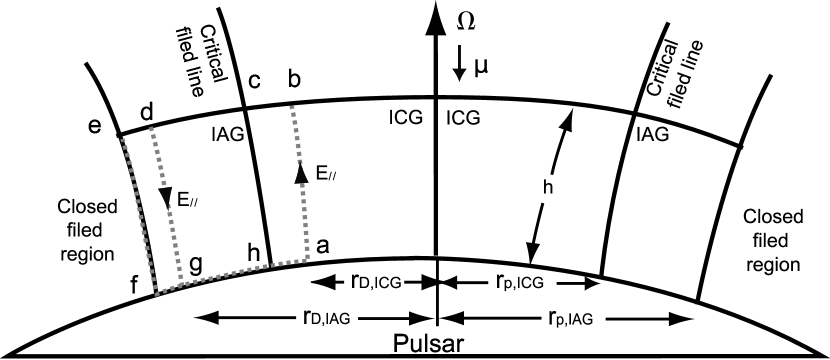
For the inner gaps, the typical gap height is smaller than the polar cap radius, and one can use the 1-D approximation of the Poisson equation in the co-rotate frame, i.e. , where is the longitudinal distance measured from the surface along the curved magnetic field lines, and is the parallel component of the electric field with respect to the magnetic field, is the charge density and is the GJ charge density. This equation governs the electric field along the magnetic field (i.e. segments “ab”, “ch”, “dg” and “ef” in Fig.1). The boundary condition equation is at the upper boundary of the gap (i.e. segment “edcb”).
When the gaps are re-generated after each sparking process, since opposite charged particles leave the ICG and the IAG regions, respectively, the sign of is the opposite in the two gaps. The Poisson equation above shows that the directions of are also different in the IAG and ICG. We expect that at the boundary between ICG and IAG (line “ch”) the parallel electric field vanishes. That is .
We handle the electrodynamics in the co-rotate frame. For any close circuits (e.g. “defg”, “abch”), one has . In the closed magnetic field region , so . As discussed in RS75, we have . Thus for the IAG, one has . When considering the boundary condition between the two gaps one has . Also is satisfied for the same reason as in the discussion of the IAG case. One can get . Therefore for the IAG and the ICG the perpendicular electric field is directly linked to the parallel electric field. Becasue the parallel electric fields in the IAG and the ICG have different directions (i.e. and have different signs), the perpendicular electric fields in the two gaps are also different. The drifting velocity have opposite signs in the ICG and the IAG, because the direction of magnetic fields is the same in the two gaps. This proposes a fundamental physical process to understand the bi-drifting phenomenon.
3 The inverse Compton scattering (ICS) model of pulsar radio emission
Any radiation model possessing a symmetrical radiation beam is not applicable to PSR J0815+09. If the radiation beam is symmetrical, the 2nd and 3rd components should come from the same beam, so they should have a same drifting sense which contradicts the data. When the aberration and retardation effects are considered, the ICS (inverse Compton scattering) model naturally predicts an asymmetric beam and offers a natural mechanism to interpret the phenomenon.
The ICS model (Qiao & Lin, 1998; Xu et al., 2000; Qiao et al., 2001, 2004) suggests that the observed radio emission comes from different emission heights and each sparking ring can, in principle, lead to several emission cone-shaped beams. Following Qiao and Lin (1998), one can get the so-called “beam-frequency figure” of the ICS model, which naturally gives rise to a narrow central core emission component and two conal components, meeting Rankin’s (1983; 1993) empirical proposal from radio pulsar data. Another remark is that the three-component scheme is an average picture, which resembles Manchester’s (1995) “window function” scheme. Depending on the line of sight, different number of emission components at a particular observing frequency can be observed. That PSR J0815+09 is observed as a drifting pulsar means that the line of sight sweeps across the beam rim rather than cutting the rim tangentially. For the latter case periodical variation of the pulse intensity rather than sub-pulse drifting should be observed. It is likely that the line of sight misses the narrow core beam and only sweeps the two conal beams. In this way, there are four conal radiation beams in the system, two of which come form the IAG while the other two come from the ICG. Generally the four beams should form eight pulse components. There are still several important issues for determining the beam morphology. One thing to put in consideration is the aberration and retardation effects. Another one is the radiation process of inverse Compton scattering.
Because different emission components are emitted at different heights, the retardation and aberration effects must be taken into account, and they are found to be important to determine the real emission morphology. These two effects will smear the leading radiation components and strengthen the trailing components (Qiao & Lin 1998, Qiao et al. 2004, Dyks et al. 2004). From the simulations (Qiao & Lin 1998, Dyks et al. 2004), it is found that the trailing components are about 2 orders of magnitude brighter than the leading components if the radio waves are superposed coherently. For incoherent superposition, the contrast should be still 1 order of magnitude.
In the ICS model, the observed radiation comes from the inverse Compton scattering between the high energy secondary particles and the low frequency electromagnetic wave (EM wave) generated by the polar gap sparking process. The intensity of the low frequency EM wave is a function of the direction angle (i.e. ), where is the angle between the radiation direction and the electric dipole moment. When taking the rotation effect into account, the leading and the trailing radiation sites at a same height do not have the same angle respected to the direction of the spark’s electric moment, so that they do not possess the same intensity of the low frequency EM wave. This effect will intensify the leading components and weaken the trailing components. The ratio of the leading low frequency wave intensity () to trailing intensity () can be given by the equation , when the inclination angle is and the spark is a pure dipole. This effect can lead to an intensity contrast of 2 orders of magnitude between the leading and trailing pulse components for coherent radiation or of 1 order of magnitude for incoherent radiation. Beside the two effects above, other potential mechanisms may also play a role. For example, if the polar gap sparks are triggered by the incoming -ray photons, the geometry configuration of the pulsar, the beam direction and the -ray photon source direction respected to the pulsar will all affect the intensity ratio of the leading and the trailing components.
Comparing among these effects, the first one is the common situation. So in most cases, the trailing components may be the ones that are observed. However, we can not exclude other possibilities discussed above, and will take it as a basic assumption that the radiation beam is asymmetrical, and that only one half of the components can be observed. Such an assumption has received observational supports, since some pulsars are already observed to have asymmetrical pulse profiles. This assumption can be tested by high quality polarization observations, which may indicate whether the leading or the trailing components are observed.
4 Simulations of sub-pulse drifting
To simulate the drifting pulse patterns, two parameters are included, i.e. the number of the sub-beams in each beam and the drifting rate of each pulse component. The numbers of the sub-beams are calculated theoretically, and the drifting rates can be obtained from the simulations, which would be used to infer the dynamical structure of both gaps.
Gil & Sendyk (2000) suggests that the number of the sparks that can be observed in drifting pattern is given by , where is the number of sparks, is the height of the gap, is the radius of the sub-pulse drifting trajactory which is given by . For the parameters of PSR J0815+09 (P=0.645s and G, McLaughlin et al. 2004), it can be shown that cm for the IAG and cm for the ICG, where is the stellar radius, is the radius of light cylinder. For a resonance inverse Compton scattering gap, the gap height is cm (Zhang et al. 1997a, ), where is the surface magnetic field in unit of G, where the curvature radius of the magnetic fields is taken as cm. So the IAG holds observed sparks while the ICG holds sparks. These two parameters will be put in our simulation for the drifting patterns. Assuming a same intensity for each component within the gap, we can also calculate the integrated pulse profile.
The drifting rates of the sparks depend on the electric structure of the gaps. However many uncertainties involved in the gaps (Zhang et al. 1997b, ; Gil et al., 2003; Qiao et al., 2004) prevent us from retrieving solid information for the drifting rates. Here we use the observational drifting rates to constrain the gap models. From the theoretical sub-beam number and the observed drifting patterns, we get the drifting rates in both gaps. The simulated results and observations are compared in Fig.2.

5 Results and discussion
By considering both the ICS process and the sparks from the IAG and the ICG, we have demonstrated that the bi-drifting phenomenon observed in PSR J0815+09 is naturally interpreted. This result also lends support to the existence of the IAG. Some parameters and effects related to our simulation are discussed as follows.
(1) The gap heights. Assuming that the spark diameter in the polar gap is the same as the gap height (Gil & Sendyk, 2000), we have used the resonance inverse Compton scattering induced polar gap model (Zhang et al. 1997b, ) to calculate the gap height to get the spark number in the polar cap. One requirement to the height of the sparks is that some sparks must take place in the IAG. The height of a resonance inverse Compton scattering induced gap in our simulation is consistent with this condition.
(2) The drifting rates. The drifting rates derived from the observation give us insights into the electric structure of the two gaps. The average parallel electric field in the gap can be estimated with . From §2, we know that the perpendicular electric field can be estimated as (see also Gil et al. 2003), where is the transverse spatial dimension of the sparks and has cm. The drifting velocity of the sparks is therefore , where is the speed of light, and the period for a spark to make a circle in both gaps can be written as , or
| (1) |
The period for a subpulse to reappear at a same phase is defined by , where is the number of sparks in a circle. Since both the IAG and the ICG have the same height and hence, the same , from Eq.(1) one gets
| (2) |
The simulation gives , and from §4, we have (Fig. 1). So . This indicates that the absolute charge density deviation from in the ICG is roughly the same as that in the IAG, although a charge deficit presents in the ICG while a charge excess presents in the IAG. Also the in the ICG is roughly the same as in the IAG but with a different sign. The sub-pulse drifting phenomenon offers a diagnostic tool for the plasma near the polar cap region.
The theoretical drifting period of a vacuum gap for PSR J0815+09 should be order of 1 s (Eq. (1) and put ) and is much shorter than the fitted value s. This has been also noticed earlier by Gil et al. (2003). There are three possible ways to solve this problem. One is to conclude that both the IAG and the ICG are not vacuum gaps, so that only a small charge density deviation from the GJ charge density is allowed. In order to match the observations, only a deviation from the GJ density in both gaps is required. This would naturally reduce the drifting rates, and is consistent with the partial screening picture (Gil et al. 2003). It is also consistent with the XMM-Newton observation results for another drifting pulsar PSR 0943+10 (B. Zhang, D. Sanwal & G. G. Pavlov 2004, in preparation). In such a case, an unsteady space charge limited flow may play an important role, and a detailed model is called for. The second reason is overestimating the drifting velocity, because the method above just give the average value of which is larger than that at sparking location. The third way to solve the problem is to take into account the drifting dynamics, in which the drifting velocity is not the velocity. Again more detailed investigations are needed. It should be noted that the subpulse drifting in the two gaps depends on the global electric property of the pulsar. Two gaps interact with each other via the boundary condition. So a physically reasonable and complete drifting subpulse model should at least includes a global electric solution of pulsars.
It is found that within the observation data span, the four pulse components keep a phase relationship at least within 120 pulses (77s). Our Eq.(2) suggests that in both gaps are roughly the same. A further physical possibility is that the two gaps may interact with each other. Dynamical system theories prove that for two quasi-periodical systems, if there are some small nonlinear interactions, the two systems will be locked into a nearby frequency with a rational ratio (Jensen et al., 1983). Because of the interactions between the two gaps, the two drifting frequencies may be locked into a relative constant ratio in our model, so that the apparent could appear the same for all four pulse components. Detailed interaction dynamics is needed to further address this problem. Some other kinds of interaction between the two gaps are also possible (e.g. Young 2004).
(3) High quality polarization observations are needed to finally verify whether the observed components are the trailing or the leading components.
In summary, the so called bi-drifting phenomenon is a newly observed touch-stone to test the radiation theories and the surface physical properties of the pulsar. Our simulated results support the coexistence of IAG and ICG. Further investigations are needed to address the questions such as how such gaps are generated.
References
- Asgekar & Deshpande (2001) Asgekar, A., & Deshpande, A. 2001, MNRAS, 326, 1249
- Cheng & Ruderman (1980) Cheng, A. F., & Ruderman, M. A. 1980, ApJ, 235, 576
- Deshpande & Rankin (1999) Deshpande, A. A., & Rankin, J. M. 1999, ApJ, 524, 1008
- Deshpande & Rankin (2001) Deshpande, A. A., & Rankin, J. M. 2001, MNRAS, 322, 438
- Dyks et al. (2004) Dyks, J., Rudak, B. & Harding, A. K. 2004, ApJ, 607, 939
- Gil & Sendyk (2000) Gil, J. A., & Sendyk, M., 2000, ApJ, 541, 351
- Gil et al. (2003) Gil, J. A. ,Melikidze, G. I. & Geppert, U., 2003, A&A, 407, 315 (astro-ph/0305463)
- Gil & Sendyk (2003) Gil, J. A., & Sendyk, M. 2003, ApJ, 585, 453
- Goldreich & Julian (1969) Goldreich, P. & Julian, W. H., 1969, ApJ, 157, 869
- Jensen et al. (1983) Jensen, M. H., Bak, P., Bohr, T. Phys. Rev. Lett., 50, 1637
- Manchester (1995) Manchester, R. N. 1995, J. Astrophys. Astr., 16, 107
- McLaughlin et al. (2004) McLaughlin, M. A., Lorimer, D. R., Champion, D. J., et al. 2004, in Young Neutron Stars and Their Environments IAU Symposium, Vol. 218 (eds. F. Camilo and B. M. Gaensler) (astro-ph/0310454)
- Qiao et al. (2004) Qiao, G. J., Lee, K. J., Wang, H. G., Xu, R. X., & Han, J. L., 2004, ApJ, 606, L49
- Qiao & Lin (1998) Qiao, G. J.,& Lin, W. P., 1998, A&A, 333, 172
- Qiao et al. (2001) Qiao, G. J., Liu, J. F., Zhang, B. & Han, J. L. 2001, A&A, 377, 964
- Rankin (1983) Rankin, J. M. 1983, ApJ, 274, 333
- Rankin (1993) Rankin, J. M. 1993, ApJS, 85, 145
- Ruderman & Sutherland (1975) Ruderman, M. A., & Sutherland, P. G., 1975, ApJ, 196, 51
- Usov & Melrose (1995) Usov, V. V., & Melrose, D. B. 1995, Austr. J. Phys., 48, 571
- Xu et al. (2000) Xu, R. X., Liu, J. F., Han, J. L., & Qiao, G. J., 2000, ApJ, 535, 354
- Xu et al. (1999) Xu, R. X., Qiao, G. J. & Zhang, B. 1999, ApJ, 522, L109
- Young (2004) Young, M. D. T. 2004, in Young Neutron Stars and Their Environments IAU Symposium, Vol. 218 (eds. F. Camilo and B. M. Gaensler) (astro-ph/0310411)
- (23) Zhang, B., Qiao, G.J., Han, J.L. 1997, ApJ, 491, 891
- (24) Zhang, B., Qiao, G. J., Lin, W. P. & Han, J. L. 1997, ApJ, 478, 313