Imaging extrasolar planets by stellar halo suppression in separately-corrected color bands
Abstract
Extra-solar planets have not been imaged directly with existing ground or space telescopes because they are too faint to be seen against the halo of the nearby bright star. Most techniques being explored to suppress the halo are achromatic, with separate correction of diffraction and wavefront errors. Residual speckle structure may be subtracted by differencing images taken through narrowband filters, but photon noise remains and ultimately limits sensitivity. Here we describe two ways to take advantage of narrow bands to reduce speckle photon flux and to obtain better control of systematic errors. Multiple images are formed in separate color bands of 5-10% bandwidth, and recorded by coronagraphic interferometers equipped with active control of wavefront phase and/or amplitude. In one method, a single deformable pupil mirror is used to actively correct both diffraction and wavefront components of the halo. This yields good diffraction suppression for complex pupil obscuration, with high throughput over half the focal plane. In a second method, the coronagraphic interferometer is used as a second stage after conventional apodization. The halo from uncontrollable residual errors in the pupil mask or wavefront is removed by destructive interference made directly at the detector focal plane with an “anti-halo”, synthesized by spatial light modulators in the reference arm of the interferometer. In this way very deep suppression may be achieved by control elements with greatly relaxed, and thus achievable, tolerances. In both examples, systematic errors are minimized because the planet imaging cameras themselves also provide the error sensing data.
1 INTRODUCTION
Optical imaging of extrasolar planets, whether from space or the ground, requires improved methods for halo suppression. These need to work over a broad wavelength band to minimize photon noise in both the wavefront sensor and planet images. Currently the best controlled starlight halos are obtained at m wavelength from both space and ground, with speckle structure at of the star intensity at arcsec radius (Schneider, 2002, Close et al, 2003). Subtraction methods such as rotation of the Hubble Space Telescope (HST) and spectral differencing for ground telescopes (Racine et al, 1999) yield a detection limit for faint companions at contrast. Order-of-magnitude improvements of these methods may be adequate to image massive, young giant planets in wide orbits, but older and less massive giants will generally be much fainter, even when heated by the star. Fainter still will be terrestrial planets, thus an Earth in a twin of the solar system at 10 pc would appear in reflected light at of the sun at 0.1 arcsec maximum separation. Detection at such faint contrast will likely require new and more powerful techniques, to directly reduce the photon flux (and noise) of the speckle halo, while maintaining exquisite control of systematic errors.
Most proposed optical configurations for deep halo suppression are inherently achromatic, involving a combination of very efficient apodization or coronagraphy (Kasdin et al, 2003, Guyon 2003 and Gonsalves and Nisenson, 2003) with active correction of wavefront errors (Trauger et al., 2003), and, in some concepts, also of pupil amplitude (Littman et al., 2003). For imaging very close to the star, where terrestrial and old giant planets are likely to be found, the halo component from optical errors is set by lower-order terms in the wavefront aberration, and these can be corrected by deformable mirrors of high accuracy but modest spatial resolution (Malbet, Yu & Shao, 1995). However, if wavefront measurements are made across the pupil to determine even low-resolution correction coefficients, they would need to be both finely detailed and highly accurate, because any under-sampled high-order structure will alias to low order.
This difficulty can be overcome if wavefront and amplitude errors are derived from focal plane measurements. Thus, improved measurement accuracy for phase and amplitude corrections to be applied at the pupil is obtained by phase diversity techniques applied to focal plane images (Malbet et al, 1995, Jefferies et al. 2002). This method was used to measure in detail the HST primary mirror aberrations (Roddier & Roddier, 1993). All focal plane techniques require the weak halo fluxes to be sensed in limited wavelength bands, and multiple channels will be needed to improve the sensitivity set by photon noise. When rapid corrections are based on wavefront measurements made in the pupil plane, the limit to wavefront accuracy set by photon noise results in a halo with very weak speckles containing just a few photons each (Angel, 1994). It can be shown that focal plane measurements of the weak halo speckles themselves can give the same accuracy and level of suppression, provided the same total bandwidth is used (Angel, 2003). Focal plane measurements have the advantages that accurate calibration is not needed, because the measurement is null, and non-common-path errors are eliminated if the same detectors are used to provide the deep integrated planet images as well as instantaneous wavefront data. For our application in which the star image must be blocked, it is convenient to derive the errors interferometrically rather than by phase diversity, obtaining the complex amplitude of the weak residual halo with the aid of a reference beam derived from the blocked starlight (Angel, 2003).
2 HALO SUPPRESSION IN NARROW BANDS
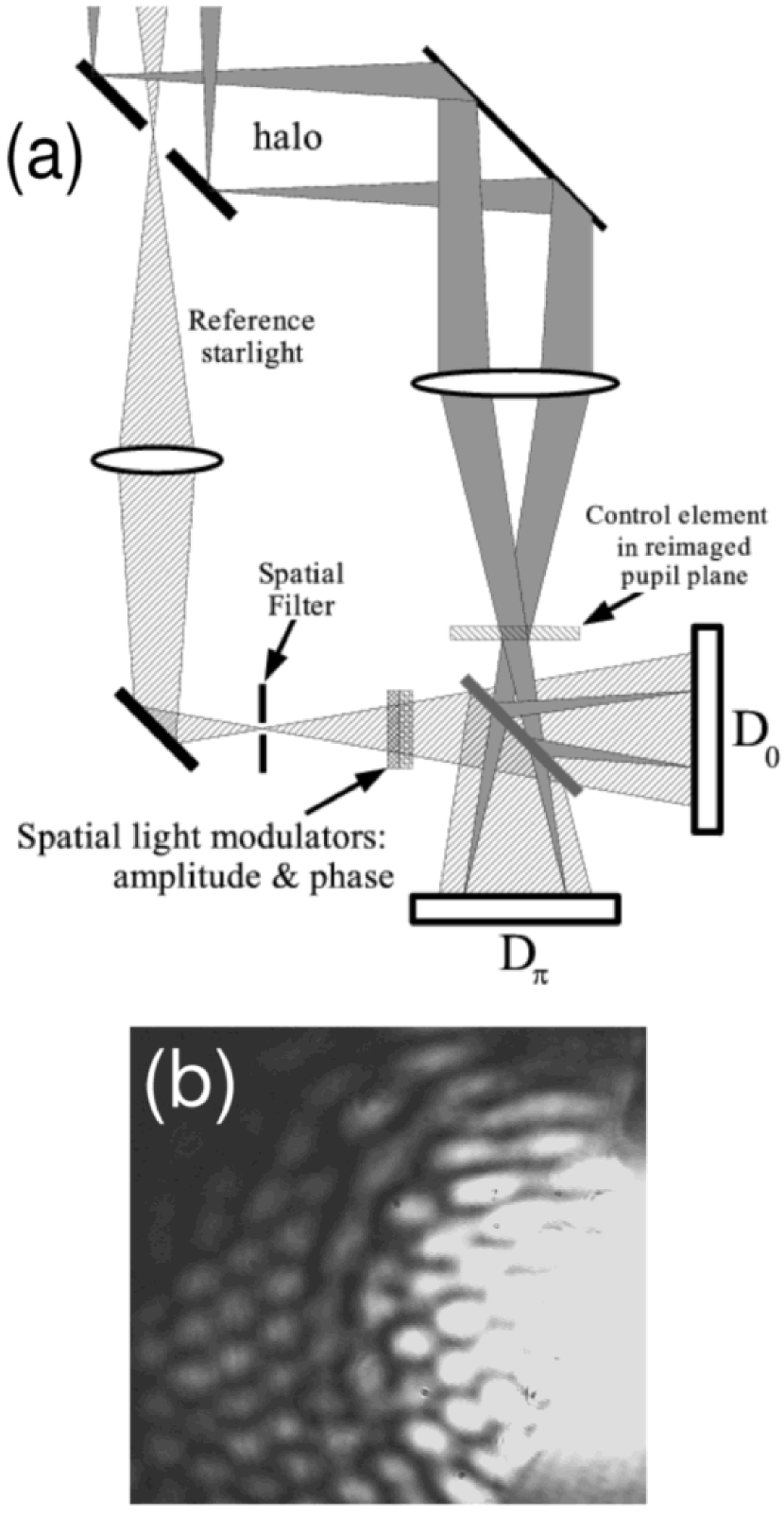
Since multiple wavelength channels are desirable for accurate wavefront sensing, it makes sense to explore the potential for passive and active corrections within each limited bandwidth channel to directly suppress the halo. New modes then become possible, because separate correction of diffraction effects and wavefront errors is no longer required. To implement such schemes, an initial separation of the telescope image into multiple wavelength star images would be made with cascaded dichroic beamsplitters or a field grating (Bonnet & Courtès 1962). Labeyrie (2002) has pointed out one approach, in which a conventional coronagraph is followed by a second stage reimaging device. In it the halo speckle phases are actively modified to be all the same, so at the center of an intermediate quasi-pupil their energy is concentrated in a central spot that can be blocked. In our concept for suppression, a coronagraphic interferometer is used to both measure and suppress the halo in a servo loop, as shown schematically in figure 1. The active elements to control phase and/or amplitude are placed at the pupil image formed in the signal arm, or in the reference beam arm to modulate the reference image. One such instrument would be placed at each narrowband star image. In operation at the telescope, the corrections to be applied are determined from measurements of the complex amplitude at each focal plane image pixel, obtained from images recorded before and after a phase shifts of in uniform amplitude reference beams.
Multiple instruments, each with two-dimensional arrays of active elements, may at first seem a daunting proposition, but suitable small MEMS deformable mirrors and liquid-crystal spatial light modulators for intensity and phase control (Littman, 2003) are becoming available, as are CCDs with gain for use as fast, photon-counting arrays (Mackay, 2001). We consider below two new modes of operation. The first is a phase-only alternative to separate apodization and wavefront correction. In the second, conventional apodization and wavefront correction is followed by a second stage in which the residual halo is further reduced by destructive interference.
3 METHOD I: PHASE CORRECTION OF BOTH DIFFRACTION HALO AND WAVEFRONT ERRORS
In this method, the full halo (including diffraction rings) is suppressed not by apodization or Lyot stop, but by modulation of phase across the pupil. The basic idea is to superpose Fourier phase components across the pupil that create the complex amplitude at each spot in the focal plane needed to null out the measured value. This is not possible over the whole focal plane, as can be seen from symmetry considerations. Thus the complex amplitude of the diffraction halo is Hermitian, while from pupil phase modulation it is anti-Hermitian, so correction can only be made over half the focal plane. Also, the suppression is more efficient if the outer radius is limited, so we adopt a “D”-shaped nulled region in the focal plane. The required pupil phase shifts are found by iterative Fourier transform of the complex halo amplitudes measured within the D, and are of order 1 radian. We envisage that the phase pattern needed to suppress diffraction would be figured permanently on the surface of a deformable mirror, and the active control used to clean up residual errors. Phase shifts made by displacement to correct diffraction can be accurate only at one wavelength , and will be systematically off at neighbouring wavelengths. For reasonably small changes in wavelength, the relative phase error is given by , therefore there will be a chromatic increase in the halo intensity that varies as times the original halo intensity.
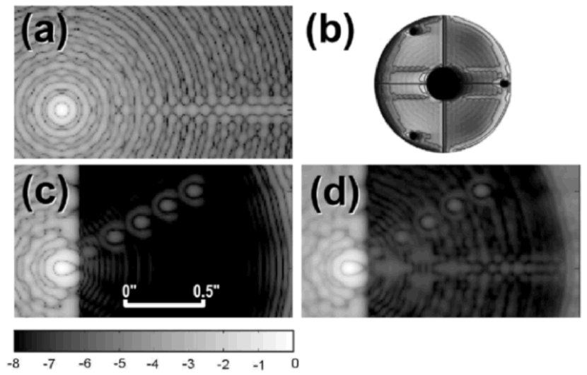
As an illustration, we show this method applied to the HST in figure 2. Obscuration of the primary mirror by the secondary and supports results in a complex diffraction pattern. The optimized pupil phase modification yields about four orders of magnitude reduction for monochromatic light, with only modest loss of energy (the Strehl ratio is 43%). We have modeled the reduced halo suppression for finite bandwidth of 10%. The contrast at radius (0.15 arcsec at ) averaged over the band is , still 3000 times below the uncorrected diffraction level.
Such deep suppression and good throughput close to the star compares favorably with conventional coronagraphy. HST’s NICMOS coronagraph with a hard field stop of radius 2.1 allows detection of companions as close as 2.6 – 3.7 , but with suppression of only (Schneider 2002). A more aggressive coronagraph for HST, including optimized correction of low-order optical errors, could yield strong suppression of , but at larger radius (7.5 ) and with only 18% planet transmission (Malbet et al. 1994, 1995). A valuable aspect of the new method is that its deep suppression of diffraction and scattered halo can be maintained by adjustments with deformable mirrors alone, avoiding the reliance of conventional coronagraphs on precise manufacture and placement of a pupil mask. It will be particularly powerful for complex or obstructed pupils for which apodization and Lyot stop methods are not very efficient (Sabatke et al, 2003). For example, it could be used to correct the halos caused by gaps and phase steps at the segment boundaries of the James Webb and Keck telescopes.
4 METHOD II: ACTIVE HALO NULLING
For deepest suppression over the full annular aperture, apodization would be combined with a second operational mode we now describe. The idea is to suppress the residual halo directly, by destructive interference in the focal plane. For this mode, the interferometer of figure 1 would be configured as a coronagraph, with halo suppression achieved in the first instance by apodization preceding the interferometer. Based on a Fourier transform of the star halo’s measured complex amplitude, the deformable mirror at the Lyot stop within the coronagraphic interferometer would be adjusted to reduce the halo from phase errors. Some faint speckles will remain, because of limits to the manufacturing accuracy of the field and Lyot stops and in the setting of the phase correction device. Their complex amplitudes would be re-measured, and the reference beam would be modulated to create a corresponding “anti-halo” with the same amplitudes but opposite phases. Destructive interference would then further reduce the halo. A planet image would be interpreted by the system as a speckle, but could not be suppressed, since it is incoherent with the starlight. Techniques for complex amplitude control with deformable mirrors and spatial light modulators are described by Gonsalves, 1997, Roggemann & Lee, 1997 and Littman et al 2003.
The additional reduction achievable in this way depends on bandwidth because of the radial stretching of speckles with wavelength. Remembering that phase changes by for a radius change of (figure 1b), we find , where is the full bandwidth and is the field radius in units of . is the effective aperture for resolution after apodization.
The value of this second approach is that the accuracy now required for additional wavefront and amplitude control is much relaxed, because the complex amplitude to be adjusted is that of the weak interfering beam, not the full starlight beam. Thus, no matter how faint the starting halo, if we desire additional suppression by a factor of 100, the accuracy required in measuring and setting the anti-halo is only radians in phase and 10% in amplitude. Such modest requirements are readily achievable with liquid crystal modulators of limited phase resolution.
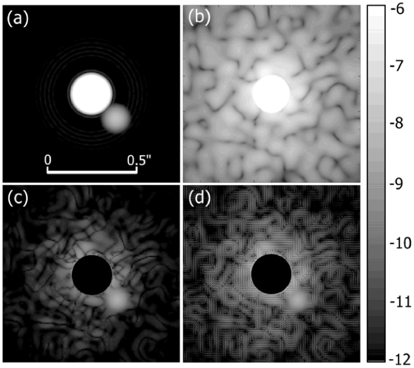
Figure 3 shows an example of suppression at the level required for detection of close-by Earth-like planets. The case modelled is a 4 m space telescope, heavily apodized for suppression, but degraded by residual amplitude and phase errors that result in a halo of at 0.2 arcsec. When the focal plane nulling is applied, cancellation to a level of is obtained, even allowing for 5% bandwidth. To minimize photon and speckle noise, measurements from 6 to 10 bands would be combined. Optimum settings for the global and local correction elements would be worked out together. In this example, the required accuracy for the “anti-halo” setting is times more relaxed than that assumed for the initial direct pupil correction (0.2 nm rms in wavefront and 0.25% in intensity at 0.25 m scale).
5 DISCUSSION
In general, a servo correction system will be necessary to repeatedly correct small distortions that develop in the wavefront. Only a few photons per speckle need be recorded over the full spectral band before a useful correction can be made. Repeated corrections made in this way will ensure that the halo flux is at the minimum possible level, and since each speckle is corrected before it has a chance to build up to more than a few photons, speckle noise in each cycle is held close to the level of halo photon noise.
This approach is valid for both ground and space telescopes. The main differences are in the achievable suppression limit and in the servo cycle time (Angel, 2003). For ground telescopes, the wavefront is continuously perturbed by evolving atmospheric turbulence. While some evolution can be predicted and compensated, there will remain an unpredictable component that causes speckles at the few photon level to develop on a scale of a few tenths of a millisecond, depending on telescope aperture and seeing conditions. The corresponding halo brightness for telescopes of 8 to 30 m aperture at micron wavelength is likely to be – of the star. For optical coronagraphs in space, the relative stability of the wavefront will permit much better halo suppression. But once the halo is at a level below that of the zodiacal background, there is little advantage in going further. For a telescope of a few meters aperture imaging at microns, this limit corresponds to of the star. In the photon noise limit, limiting sensitivity to exoplanets varies as halo intensitycycle time, and is comparable for these ground and space telescope examples.
The level of suppression needed for ground telescopes should be achievable by method I with a single very fast-acting deformable mirror. The method has the advantage, mentioned above, that complex diffraction spikes from very large segmented mirrors can be suppressed with little loss of light. For the much higher suppression needed in space, the active halo nulling method will be preferred.
References
- (1) Angel, J. R. P. 1994 Nature 368, 203
- Angel (2002) Angel, J. R. P. 2002 in ASP Conf Series 294, 543
- Angel (2003) Angel, J. R. P. 2003, in ESA SP-539, in press
- Bonnet and Courtes (1962) Bonnet, R. M. & Courtès, G. 1962, AnAp, 25, 367
- Close et al (2003) Close, L. M., Lenzen, R., Biller, R., Brandner, W. & Hartung, M. 2003, in Science with adaptive optics, ESO, in press
- Guyon (2003) Guyon, O. 2003, A&A, 404, 379
- Gonsalves (1997) Gonsalves, R. A. 1997, OptL, 22, 588
- Gonsalves & Nisenson (2003) Gonsalves, R. & Nisenson, P. 2003, PASP, 115, 706
- (9) IEEE 1979, Programs for Digital Signal Processing. (New York: John Wiley & Sons), Program 5.2.
- Jefferies et al (2002) Jefferies, S., Lloyd-Hart, M., Hege E. K. & Georges J. A. 2002, ApOpt, 41, 2095
- Kasdin et al (2003) Kasdin, N. J., Vanderbei, R. J., Spergel, D. N., Littman, M. G. 2003, ApJ, 582, 1147
- Labeyrie (2002) Labeyrie, A. 2002, in ESA SP-514, 245
- Littman et al (2003) Littman, M. G., Carr, M., Leighton, J., Burke, E., Spergel, D. N. & Kasdin, N. J. 2003, SPIE, 4854, 405
- Mackay (2001) Mackay,C. D., Tubbs, R. N., Bell, R., Burt, D. J., Jerram, P. & Moody, I. 2001, SPIE 4306, 289
- Malbet, Shao, and Yu (1994) Malbet, F., Shao, M. & Yu, J. 1994, SPIE 2201, 1135
- Malbet, Yu, and Shao (1995) Malbet, F., Yu, J. W. & Shao, M. 1995, PASP, 107, 386
- (17) Racine, R., Walker, G. A. H., Nadeau, D., Doyon, R. & Marois, C. 1999 PASP 111, 587
- Roddier and Roddier, (1993) Roddier, C. & Roddier, F. 1993, ApOpt, 32, 2992
- Roggemann and Lee (1997) Roggemann M. C. & Lee, D. J. 1997, ApOpt, 37, 4577
- Sabatke et al (2003) Sabatke, E. M., Burge, J. H., Angel, J. R. P. & Sabatke D. S. 2003, in PASP, in press
- Schneider (2002) Schneider, G., 2002, in The 2002 HST Calibration Workshop, STScI, 249
- Sudarsky, Burrows, and Hubeny (2003) Sudarsky, D., Burrows, A. & Hubeny, I. 2003, ApJ, 588, 1121
- Trauger (2003) Trauger, J. T., Moody, D., Gordon, B., Gürsel, Y., Ealey, M. A. & Bagwell, R. B. 2003, SPIE, 4854, 1