11email: alvarez@mpia-hd.mpg.de 22institutetext: Kapteyn Astronomical Institute, Postbus 800, 9700 AV Groningen, The Netherlands 33institutetext: Max-Planck-Institut für Astronomie, Königstuhl 17, D-69117 Heidelberg, Germany 44institutetext: Dept. of Physical Sciences, University of Hertfordshire, College Lane, Hatfield AL10 9AB, United Kingdom
Constraints in the circumstellar density distribution of massive Young Stellar Objects
We use a Monte Carlo code to generate synthetic near-IR reflection nebulae that resemble those (normally associated with a bipolar outflow cavity) seen towards massive young stellar objects (YSOs). The 2D axi-symmetric calculations use an analytic expression for a flattened infalling rotating envelope with a bipolar cavity representing an outflow. We are interested in which aspects of the circumstellar density distribution can be constrained by observations of these reflection nebulae. We therefore keeep the line of sight optical depth constant in the model grid, as this is often constrained independently by observations. It is found that envelopes with density distributions corresponding to mass infall rates of (for an envelope radius of 4700 AU) seen at an inclination angle of approximately reproduce the morphology and extension of the sub-arcsecond nebulae observed in massive YSOs. Based on the flux ratio between the approaching and receding lobe of the nebula, we can constrain the system inclination angle. The cavity opening angle is well constrained from the nebula opening angle. Our simulations indicate that to constrain the outflow cavity shape and the degree of flattening in the envelope, near-IR imaging with higher resolution and dynamic range than speckle imaging in 4m-class telescopes is needed. The radiative transfer code is also used to simulate the near-IR sub-arcsecond nebula seen in Mon R2 IRS3. We find indications of a shallower opacity law in this massive YSO than in the interstellar medium, or possibly a sharp drop in the envelope density distribution at distances of 1000 AU from the illuminating source.
Key Words.:
massive star formation – outflows – speckle imaging – Monte Carlo – scattering1 Introduction
Bipolar outflows appear to be a ubiquitous phenomenon during the formation of stars in all mass ranges (Bally & Lada 1983; Henning et al. 2000; Ridge & Moore 2001; Beuther et al. 2002). Low mass young stellar objects (YSOs) show highly collimated bipolar jets from a few 10 AU (Burrows et al. 1996) to several parsec (Reipurth et al. 1997; Eislöffel 2000) in length. These jets are thought to be magneto-hydrodynamically collimated in a wind formed at the inner star-disk system (e.g. X-wind, Shu et al. 1994). The jets are thought to drive the large scale molecular outflow (Masson & Chernin 1994).
The formation and collimation of outflows in massive YSOs is less well understood than in low mass YSOs. There appears to be a lack of highly collimated parsec-scale jets (Mundt & Ray 1994). In the near-IR, searches for shock-excited show traces of jets in massive star forming regions, but probably driven by low mass young stars located in the same cluster (Davis et al. 1998; Wang et al. 2003). A recent search for optical shock-excited emission in the outer parts of the outflow, yielded no evidence of jet interaction (Alvarez & Hoare, in prep.). Very close to the driving source, there is also not clear evidence that jets are the rule in massive YSOs. In some cases, the free-free radio emission from the inner wind shows a jet morphology (e.g. HH80-81, Marti et al. 1993; Cep A, Torrelles et al. 1996). Such jets would have to be magneto-hydrodynamically driven, even though the OB stars themselves are not magnetically active. Magneto-hydrodynamics in the infalling rotating cloud could set up bipolar flows (Tomisaka 1998). In other cases, the ionised wind appears to be equatorial (e.g. Hoare et al. 1994; Hoare & Muxlow 1996; Hoare 2002). Theoretical models show that radiation pressure in massive young stars can drive gas off the surface of a disk, producing a predominantly equatorial wind (Drew et al. 1998; Drew & Proga 2000). Any initial flow maybe hydrodynamically collimated into a bipolar flow by the flattened surrounding cloud (e.g. Delamarter et al. 2000). These alternative theories will predict different morphologies for the base of the outflow cavities carved out. These variations in morphology occur at scales of a few 100 AU, which at the typical distances to massive YSOs of kpc, correspond with angular sizes of 01. Therefore, high resolution techniquies are fundamental to study the impact of the the outflow in the surrounding material.
In a related paper (Alvarez et al. in prep., hereafter Paper I), we show high resolution near-IR speckle images which trace the circumstellar matter around massive YSOs at scales of a few 100 AU. The extended emission that is seen towards some of the sources can be interpreted as scattered light in an outflow cavity due to its monopolar morphology. This intepretation is supported in some cases by the blue colours of the nebula (e.g. Mon R2 IRS3, Paper I, Preibisch et al. 2002). Furthermore, polarimetric speckle imaging of the reflection nebula in the massive star forming region S140 IRS1 (Schertl et al. 2000) shows a centrosymmetric pattern which is typical of scattered light.
Intuitively, one can imagine that depending on the properties of the dust, the shape of the cavity, the density distribution and the orientation of the system with respect to the observer, the resulting reflection nebula will change. The morphology of the cavity is particularly important because it is shaped by the interplay between the infall and the outflow. For instance, it is expected that an equatorial or wide-angled wind will produce a cavity with a wide openig angle near the star. However, a jet is expected to open a rather narrow cavity.
Radiative transfer simulations have been widely used to generate synthetic nebulae that resemble the observations (Lazareff et al. 1990; Whitney & Hartmann 1992; Kenyon et al. 1993; Fischer et al. 1994, 1996; Whitney et al. 1997; Lucas & Roche 1997, 1998; Wolf et al. 2002). The work by Lazareff et al. (1990) was based on a ray-tracing code and it was focused mainly on the effect produced by different disc models on the synthetic nebulae. The authors compared the general features of the model images with previous seeing-limited images of the low mass systems HL Tau and L 1551 IRS5. Whitney & Hartmann (1992), Kenyon et al. (1993) and Whitney et al. (1997) developed a Monte Carlo code to investigate how the nebula morphology and the near-IR colours of the synthetic images vary with different model parameters. In particular, Whitney et al. (1997) used their code to constrain the colours of the central source, the dust model and the envelope density distribution in a sample of 20 low mass YSOs. Fischer et al. (1994) and Fischer et al. (1996) developed a new Monte Carlo scattering code and they focused on exploring the effect of different dust models in the synthetic images. Lucas & Roche (1997) and Lucas & Roche (1998) compared synthetic nebulae produced with their Monte Carlo code with high resolution multi-colour observations of reflection nebulae associated with low mass YSOs. From this comparison, they could constrain some parameters defining circumstellar density distribution as well as the dust model for several sources. Recently, radiative transfer Monte Carlo codes have been developed to simulate scattering by non-spherical dust particles Whitney & Wolff (2002); Wolf et al. (2002); Lucas (2003).
These previous models have focused predominantly on low mass YSOs. Here, we apply the Monte Carlo code of Lucas & Roche (1998) to high mass YSOs, where the infall rates are much higher. We also adopt an observational approach, by presenting a grid of models in which as each parameter is varied, the overall density is scaled too to keep the optical depth along the line of sight constant. This is because the line of sight optical depth is often well constrained from other data such as the optical depth of the 9.7 m silicate feature or the colour of the star. The models are decribed in Sect. 2. The grid of models is presented in Sect. 3. In Sect. 4, we use the models to constrain the density distribution in Mon R2 IRS3. Some concluding remarks are shown in Sect. 5.
2 Models
We used the Monte Carlo code of Lucas & Roche (1997, 1998) with a set of parameters adapted to massive YSOs. The models consist of a central star surrounded by a dusty flattened envelope. A disc characterizes the density distribution near the equator. The model also includes an empty bipolar cavity opened by the outflow in the circumstellar matter. The photons emerging from the central source are scattered off the dust grains in the envelope and disc. Each photon can suffer several scattering processes until it is either absorbed, or escapes. All photons traveling in a particular direction are binned, and projected onto the image plane.
The envelope is described by a density distribution resulting from the collapse of a slowly rotating cloud (Ulrich 1976; Terebey et al. 1984). The density () at any point (r, ) is given by Eq. 1,
| (1) |
| (2) |
where represents the mass infall rate and M is the mass of the central source. is the centrifugal radius, which determines the degree of flattening of the distribution. Flatter density distributions are characterised by larger centrifugal radii. , where is the position angle of each particle with respect to the polar axis. represents the initial position angle of each infalling particle. The equation of motion of the infalling particles (Eq. 2) should be satisfied at every point (see Ulrich 1976, for details).
The disc plays a passive role in the models presented here. It absorbs and scatters the radiation from the central star, but it does not emit. We use Eq. 3 to describe the disc density structure,
| (3) |
where R and z satisfy the relation , represents the density in the midplane at the surface of the star, and is the radius of the star. is the disc scale height. parametrises the degree of flaring on the disc. We tried steady Keplerian discs ( and ) as well as geometrically thin and optically thick discs ( and ) (Lazareff et al. 1990; Whitney & Hartmann 1992).
An empty cavity represents the material evacuated by the outflow in the envelope. The shape of the cavity must be determined by the interplay between the infall and outflow processes. However, the lack of knowledge of these processes makes the choice of the cavity shape somewhat arbitrary. For some of the models a conical cavity was used,
| (4) |
where B represents the tangent of the cavity half-opening angle. For other models, a parabolic cavity was used, which is represented by the expression,
| (5) |
where the constant A determines the curvature of the parabola, and represents the radius of the cavity at the equator. The cavity opening angle () is defined as twice the angle formed by the z axis and the line connecting the intersection between the parabola and the equator with the intersection between the parabola and the outer sphere.
For the dust, we used the mixture of Mathis et al. (1977). The values of the opacities are obtained using a dust to gas ratio by mass of . The optical constants and albedos for this mixture were chosen from Draine & Lee (1984) and Draine (1985). The values used for the opacity are 2.0, 3.8 and , and the values for the albedo are 0.22, 0.34 and 0.45, in the K, H and J bands respectively. The phase function that describes the scattering is within the Rayleigh approximation in the K band, and becomes gradually forward throwing towards the J band.
3 Grid of models
In this section, a grid of models is presented (see Table 1) to illustrate how variations on the input parameters affect the morphology of the model images. All models shown have an outer radius = 4700 AU, and are assumed to be located at a distance of 1 kpc. Since we aim to compare the model predictions with typical speckle observations in 4m-class telescopes, synthetic images are generated with a size of pixels at a pixel scale of 006. Our choice of keeps the outer boundary of the models outside the field of view of the synthetic images. The images were convolved with a gaussian with a FWHM=02, which is the typical resolution achieved with speckle imaging in 4m-class telescopes (see Paper I).
The input parameters are varied with respect to a fiducial model (K01, in Table 1). The fiducial model consists of an envelope with a centrifugal radius of 50 AU and a mass infall rate (note that are typically inferred for low mass YSOs ; Kenyon et al. 1993; Lucas & Roche 1997; Whitney et al. 1997, e.g. ). The mass infall rates used in our grid are consistent with envelope models in massive stars (Wolfire & Cassinelli 1986; Maeder & Behrend 2002). This mass infall rates, though, would be smaller for models with a larger outer radius. The model also has a geometrically thin but optically thick disc ( and ) of radius = 250 AU and = kgm-3. A conical cavity with a radius at the equator of 100 AU and an opening angle = represents the effect of the outflow in the envelope. The central source is assumed to be a star with a radius = 10 . The number of input photons in model K01 is . Only 8.7% of these photons form part of the output (see column 9 in Table 1). The other 91.3% is absorbed either in the disc (9.3% of the total) or in the envelope (79.2%). There is a small fraction (2.8%) that is absorbed by the star itself after being scattered. The optical depth along the line of sight of the fiducial model in the K band (= 8 in Table 1) corresponds to an extinction in the K band of = 8.6 mag. If the extinction law of He et al. (1995) is used, this corresponds to a visual extinction of 80 magnitudes, i.e. an optical depth of the 9.7 m silicate feature of 4, (where from Draine & Lee 1984 was used), which is typically observed in massive YSOs.
| Moda | / | Cavb | Disc | |||||
| K01 | 100 | 50 | 250 | 8 / 45 | C20 | T | 1.11 | 0.087 |
| K02 | 100 | 50 | 250 | 6 / 45 | C20 | T | 0.47 | 0.119 |
| K03 | 100 | 50 | 250 | 7 / 45 | C20 | T | 0.77 | 0.093 |
| K04 | 100 | 50 | 250 | 9 / 45 | C20 | T | 1.38 | 0.173 |
| K05 | 100 | 50 | 250 | 10 / 45 | C20 | T | 1.44 | 0.066 |
| K06 | 100 | 50 | 250 | 8 / 75 | C20 | T | 0.47 | 0.068 |
| K07 | 100 | 50 | 250 | 8 / 60 | C20 | T | 0.77 | 0.138 |
| K08 | 100 | 50 | 250 | 8 / 25 | C20 | T | 1.80 | 0.350 |
| K09 | 100 | SPH | 250 | 8 / 45 | C20 | T | 1.17 | 0.087 |
| K10 | 100 | 100 | 250 | 8 / 45 | C20 | T | 1.30 | 0.080 |
| K11 | 100 | 150 | 250 | 8 / 45 | C20 | T | 1.47 | 0.077 |
| K12 | 100 | 200 | 250 | 8 / 45 | C20 | T | 1.62 | 0.074 |
| K13 | 100 | 50 | 250 | 8 / 45 | C10 | T | 1.06 | 0.058 |
| K14 | 100 | 50 | 250 | 8 / 45 | C30 | T | 1.18 | 0.124 |
| K15 | 100 | 50 | 250 | 8 / 45 | C40 | T | 1.28 | 0.167 |
| K16 | 100 | 50 | 250 | 8 / 45 | C50 | T | 1.41 | 0.214 |
| K17 | 50 | 50 | 250 | 8 / 45 | C20 | T | 0.83 | 0.075 |
| K18 | 150 | 50 | 250 | 8 / 45 | C20 | T | 1.39 | 0.094 |
| K19 | 200 | 50 | 250 | 8 / 45 | C20 | T | 1.66 | 0.101 |
| K20 | 250 | 50 | 250 | 8 / 45 | C20 | T | 1.93 | 0.106 |
| K21 | 100 | 50 | 100 | 8 / 45 | C20 | T | 1.11 | 0.087 |
| K22 | 100 | 50 | 150 | 8 / 45 | C20 | T | 1.11 | 0.087 |
| K23 | 100 | 50 | 200 | 8 / 45 | C20 | T | 1.11 | 0.087 |
| K24 | 100 | 50 | 500 | 8 / 45 | C20 | T | 1.11 | 0.087 |
| K25 | 100 | 50 | 250 | 8 / 45 | C20 | F | 1.11 | 0.087 |
| K26 | 100 | 50 | 250 | 8 / 45 | P20 | T | 1.58 | 0.150 |
| J01 | 100 | 50 | 250 | 25 / 45 | C20 | T | 1.11 | 0.097 |
| H01 | 100 | 50 | 250 | 15 / 45 | C20 | T | 1.11 | 0.055 |
| HH01 | 100 | 50 | 250 | 12 / 45 | C20 | T | 1.11 | 0.063 |
-
a
Model name, composed of the filter used to generate the image, and a serial number.
-
b
Type of cavity; (P)arabolical or (C)onical, and opening angle (in degrees).
-
c
Type of disc; (F)lared or (T)hin.
-
, and are the cavity, centrifugal and disc radius in AU. represents the optical depth along the line of sight at the wavelenght of the model. The inclination of the line of sight in degrees with respect to the system axis is represented by . is the mass accretion rate in units of . is the ratio between the total number of output photons (i.e. the sum of scattered and direct photons from the star) in all directions and the number of input photons at the wavelenght of the model.
3.1 Morphology
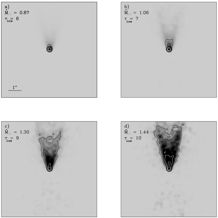
In this section, we investigate which parameters of the circumstellar density distribution can be constrained from the observed morphology of the nebula. Fig. 1 shows the effect produced in the synthetic images by varying the overall optical depth in the envelope. This is done by changing the density scaling through the mass infall rate () in the Ulrich formula. At low optical depths (Fig. 1a), there is less dust available to scatter the light, and also to absorb the direct light from the star. Therefore, the nebula becomes relatively fainter than at higher optical depths, and the only contribution to the image at a 5% level is the central star. However, at higher optical depths, the nebula becomes much more extended, since the central star becomes highly obscured and there is more dust available for scattering. Hence, only a change of 50% in the mass infall rate has a dramatic change on the appearance of the system, due mainly to the exponential dependence on the line of sight optical depth of the central star brightness. Therefore, from an observational point of view, the line of sight optical depth is the most important parameter.
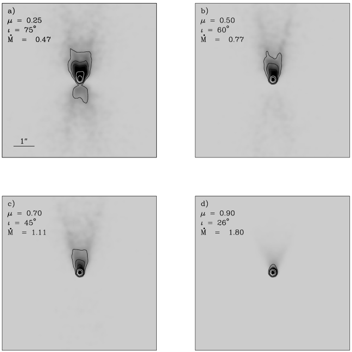
Figure 2 shows the K band images for different inclination angles of the line of sight with respect to the system axis (i.e. cavity axis). The overall density scaling has ben adjusted in each of the four models to yield the same optical depth along the line of sight as the fiducial model ( = 8). For views near edge-on (panel a in Fig. 2), the nebula is clearly bipolar at the 5% level. The receding lobe appears less bright than the approaching lobe. In this case (model K06 in Table 1), a mass infall rate 2.3 times lower than for the fiducial model was used. Even at this near-edge-on inclination, it is possible to see the central star due to the low overall density scaling. At intermediate inclinations (panels b and c), the receding lobe is not detected any more at the 5% level. At low inclinations, (panel d) a faint monopolar nebula can still be seen.

The contrast between the approaching and receding nebula () is a useful quantity to estimate the system inclination angle. Fig. 3a shows the variation of the with the inclination angle. Each point in the plot represents a model whose overall density scaling has been adjusted to yield an optical depth along the line of sight of 8 at its corresponding inclination. The flux ratio has been calculated using aperture photometry with an aperture radius of in the synthetic images. The aperture on the approaching lobe was centered at 08 from the star along the cavity axis and it includes the star itself. The aperture on the receding lobe was centered at 12 from the star also along the cavity axis and it does not include the star. This avoids sensitivity to the actual location of the apertures. For near-edge-on views (small ’s), the approaching and receding lobe have roughly the same brightness. Therefore, the is nearly 1. As increases, the approaching lobe becomes relatively brighter, and hence the value of increases. The figure also shows that the ratio becomes 100 for values of in the range between 0.70 and 0.80 (i.e for inclination angles in the range and ). Hence, a 1% upper limit in the detection of the receding lobe indicates that the system is seen under an inclination angle .
Figure 3b shows the change of due to variations in the optical depth (i.e. variations in the ) for an inclination angle of . At very low optical depths ( ) the star dominates the flux. As the opacity increases ( ), the star is increasingly obscured, and the counter-lobe starts to show up. At larger optical depths ( ), the approaching lobe starts to dominate the emission, while the receding lobe hardly changes. Hence, the ratio increases again. The contrast between the nebula lobes is less sensitive to changes in the mass infall rate than to changes in the inclination angle. Hence, in principle, the approaching to recceding lobe flux ratio can be used to constrain the inclination angle.
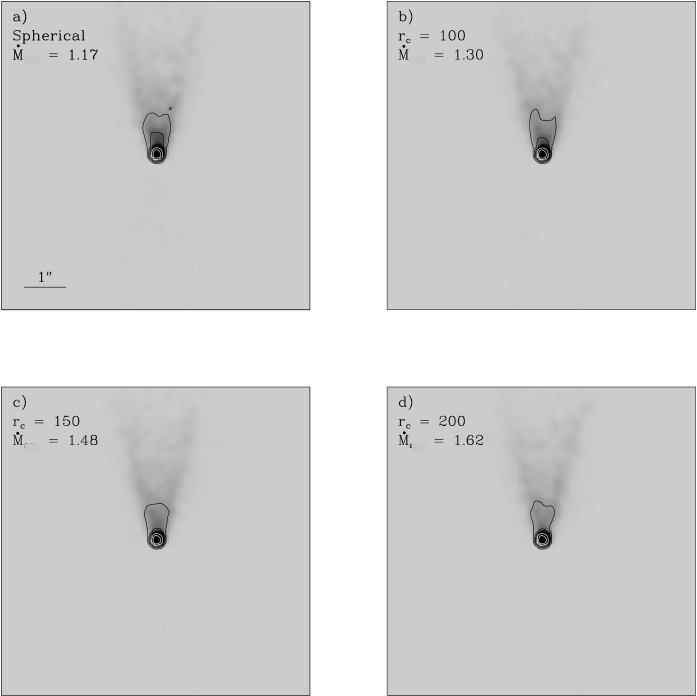
In Fig. 4, we investigate whether the shape of the envelope can be derived. The images show models with an increasing centrifugal radius (i.e. flatteness of the envelope), from panel a) to panel d). The mass infall rate for each model has again been set such that the optical depth along a line of sight at remains the same as for the fiducial model (i.e. = 8 in the K band). The fiducial model, with a centrifugal radius of 50 AU, is shown in Fig. 2c. Figure 4a represents the case of a spherical density distribution. The nebula becomes less bright as the centrifugal radius increases (panels b, c, and d in Fig. 4). Since the material is predominantly concentrated on the equatorial plane and there is less dust available in the polar regions of the envelope, where a large fraction of the scattered light is generated. However, this is a very subtle change compared to that for the line of sight optical depth o inclination angle. Hence, the reflection nebula tells us little about the degree of flattening of the envelope.
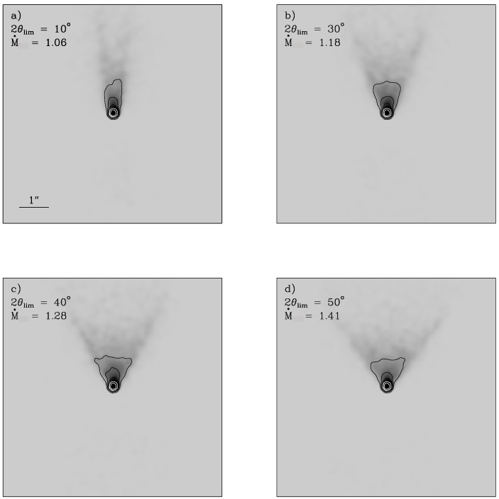
Figure 5 shows the effect of varying the cavity opening angle () on the synthetic nebulae. The mass infall rate was increased with the cavity angle to keep the same optical depth along the line of sight in all images. Unsurprisingly, the nebula opening angle appears to be larger for models with a wide-angled cavity. The significant changes on the nebula shape occur for the external contours, while the inner contours remain nearly unchanged. This is consistent with the fact that variations in the cavity opening angle will affect more the external regions of the envelope than the regions close to the cavity base. At wider cavity opening angles, more stellar photons can escape the system without being scattered. This is shown in column 9 of Table 1, where the fraction of photons (scattered and stellar) that leaves the system () is listed.
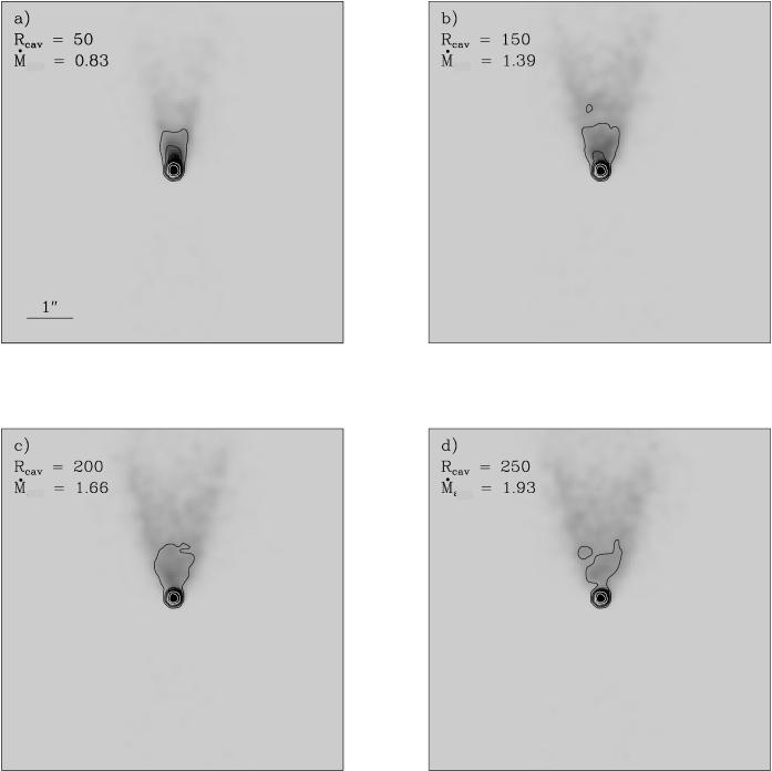
The result of varying the cavity radius at the equator from 50 to 250 AU is shown in Fig. 6. A radius of 50 AU corresponds approximately to the sublimation radius for dust in OB stars. Radiation pressure or wind interactions could increase the size of the hole. The nebula appears fainter and slightly wider for larger values of the . In this case, the differences between nebulae can also be observed in the innermost contours. This is caused by the fact that changes in will have a stronger impact in the regions of the envelope closer to the equator than in the outer regions. The total number of output photons increases by a factor of 1.4 from the model with = 50 AU to the model with = 250 AU (see column 9 in Table 1). For larger values of , similar number of photons are scattered of a larger surface. Hence, the surface bightness of the nebula decreases from Fig. 6a to d.
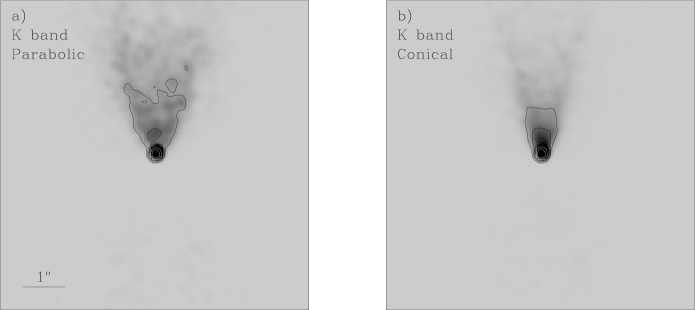
We now investigate the effect of the detailed shape of the base of the cavity. A parabolic cavity might be expected if the central wind is initially equatorial, whilst a conical cavity would arise from a jet-driven flow in low mass stars (Bachiller et al. 1995). Figure 7a shows the K band image for a model with a parabolic cavity compared with a conical nebula in Fig. 7b. The other parameters have the same values as for the fiducial model, except the overall opacity scaling, which has been enhanced by a factor of 1.4 to yield the same optical depth along the line of sight as in the fiducial model. The parabolic shape is clearly seen in the resulting nebula, as expected (Fig. 2). A larger fraction of photons escape from the parabolic model than from the conical model because the parabolic cavity is broader near the star than the conical cavity. The concave shape of the cavity walls, favours the scattering in the outer regions of the envelope, which also contributes to make the parabolic nebula more extended.
All models shown up to this point included an optically thick, and geometrically thin flat disc of radius = 250 AU. To investigate any dependence of the model images on the disc radius, we have generated models with the same parameters as the fiducial model (K01, Fig. 2a) but with varying disc radius (). No significant differences were found between the images resulting from these models and the fiducial model. We also investigated whether the introduction of a flaring disc may change the morphology of the reflection nebulae. Model K25 in Table 1 has the same parameters as the fiducial model except for a flaring in the inner disc. The values used for and in the disc equation (Eq. 3) were 15/8 and 9/8 respectively (i.e. a Keplerian disc). No relevant differences were appreciated between these images and the fiducial model. The reason is that the disc flaring angle for the value of is small compared with the line of sight inclination angle. The envelope density dominates the disc density for all inclinations ().
3.2 Dependence with wavelength
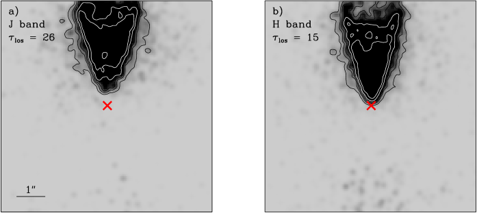
Figures 8a, 8b and Fig. 2c show the variation of the synthetic images with the wavelength (J, H and K band respectively). The geometry and density distribution for the J and H band models are the same as for the fiducial model. However, the opacities, the albedos and the scattering matrix change with wavelength. The opacities correspond with an extinction law () with an exponent . The number of photons in the input spectrum at H () is a factor of 2.00 times the number of photons at K (), and the number of photons at J () is 2.45 times the number of photons at K. The number of input photons at each wavelength was calculated using the model stellar atmospheres from Kurucz (1979). The spectral energy distribution (SED) of model OB main sequence stars were integrated in the J, H and K bands using the transmission profiles of the filters J98, H98 and K98 at UKIRT. The ratio between the number of photons emitted at two given bands approaches asymptotically to a constant value for earlier spectral types. This limit corresponds with a slope in the stellar SED of -2.4 (), which is shallower than the theoretical Rayleigh-Jeans limit (). This shallower SED is a better representation of the colours of OB main sequence stars than the Rayleigh-Jeans approximation (see the UKIRT web-page: http://www.jach.hawaii.edu/JACpublic/UKIRT/). Figures 8a, 8b and 2c show that the nebula appears more extended at short wavelengths, while the star becomes totally obscured, due to the increase in the opacity. It can also be seen that the separation between the star and the nebula apex decreases towards longer wavelengths, i.e. it is possible to probe the circumstellar density distribution closer to the star at longer wavelengths.
We now address the question of how the colours of the synthetic images vary with the different model parameters. The colour for the models can be estimated using the following expression,
where the ’s represent the number of photons within a certain aperture on each band. The ’s are the central wavelengths of the filters, and the ’s are the zero magnitude fluxes. The values used for are 1.65 and at H and K respectively, and Wmm-1 and Wmm-1 are the values for and respectively (UKIRT web-page: http://www.jach.hawaii.edu/JACpublic/UKIRT/). For simplicity, the colous shown here assume that the foreground extinction is negligible. Note that the presence of unknown foreground extinction is an added complication when models are compared with observations.

Figure 9a shows the change in the colour with the line of sight inclination angle for the fiducial model. An aperture radius of 1′′ centered at the image centre was used. The colour at all inclinations, except for the very close to pole-on, is clearly redder than the colour of the input spectrum (()inp=0.04). At edge-on inclinations (), no star is seen in either band, and the nebula at K is less extincted than the nebula at H. At intermediate inclinations, the nebula at H becomes brighter because the stellar light passes through a less dense part of the envelope. The star begins to appear at K but is not yet seen at H. The overall effect is that the colour becomes bluer. For the star brightens quickly at K, dominating the flux in this band, while the star just begins to appear at H. Hence, the colour becomes redder. At face-on views (i.e. ) the colour tends to the ()inp because the star is now seen directly through the cavity. The behaviour of the colour with the inclination angle in our simulations is different to that found by Kenyon et al. (1993) and Whitney et al. (1997). Their models become bluer at high inclination angles, while ours become redder due to the higher envelope optical depth (i.e. higher mass infall rate) and due to the fact that, at high inclinations, no star is seen in the H band.
Figure 9b illustrates how the colour varies with the overall opacity at a fixed inclination angle of . At large opacities, the colour is bluer because the reflection nebula becomes relatively brighter than the star. In Fig. 9c, we represent models with different centrifugal radii seen at a fixed inclination of . The mass accretion rate was adjusted so that all of them have an optical depth along the line of sight of 8. In the models with a larger centrifugal radius (i.e. a flatter density distribution) there is less dust available in the outer parts of the envelope, since the dust is mainly concentrated at the equator. This density enhancement in the equatorial region allows more direct light from the central star to escape (predominantly in the K band due to the low opacity) than in models with a small . The consequence is that the colour becomes slightly redder for models with large .
Figure 9d shows variations of the colour with the cavity opening angle. All models represented in this plot are seen at an inclination of , and the overall density scaling was adjusted to yield an = 8. The general trend is that at wide cavity opening angles the colour becomes bluer because more scattered photons in the outer parts of the envelope (at H, not at K) can escape from the system. This general trend is favoured by the fact that the direct light from the star is equally extincted at all cavity opening angles shown in Fig. 9d. The figure also illustrates that the colour for models with an becomes even bluer than the colour of the input spectrum. In summary, the four panels in Fig. 9 show that the change in the colour is not higher than 1 magnitude within the ranges of the parameter space investigated. Hence, the integrated colour is not particularly sensitive to the density distribution, and is unlikely to yield unique solutions for the model parameters.
3.3 Dust in the cavity
Up to now, we have assumed that the cavity evacuated by the outflow is empty. However, in a more realistic situation, one would expect that some dust may remain inside the cavity. We estimated the expected due to dust within the cavity from the typical column densities in massive outflows as follows. Ridge & Moore (2001) show that the the integrated CO (J=1-2) intensity in molecular outflows from 11 massive YSOs is, on average, 200 K. If we use the expression , where represents the integrated CO (J=1-2) intensity (Osterloh et al. 1997; Henning et al. 2000), typical column densities in the outflow of cm-2 are obtained. This yields typical visual extinctions of mag, if the expression from Bohlin et al. (1978) is used. This implies an A mag which is about 200 times smaller than the AK =8, used in our fiducial model.
To see the effect that dust in the cavity has in our simulations, we have run three models with the same parameters as our fiducial model but with an along the cavity axis of 0.1, 1 and 10 mags. A dusty density distribution within the cavity given by the expression , which is expected in a disc wind with a constant flow density distribution in a conical cavity, was chosen. The output from the models with = 0.1 and 1 are hardly distinguishable from the fiducial model. For = 10, only a few photons from the star can scape the system, and the reflection nebula is not seen at all. However, the latter value of is far larger than our previous estimate of extinction due to dust in the cavity. Therefore, for the typical extinction expected due to dust within the cavity in massive YSOs, no noticeable effect on the observable properties of our scattering models is detected. Note that this result depends on the selected shape for the density distribution within the cavity. If an optically thin uniform density distribution is chosen, the resulting reflection nebula is expected to be more extended than for an empty cavity (see Lucas & Roche 1996).
4 Model for Mon R2 IRS3 S
In Paper I, multi-colour (H and K band) speckle images of a pair of outflow cavities in Mon R2 IRS3 were presented. In this section, the data for IRS3 S are used to find observational constraints to the density distribution using the models presented in the previous section. In Figs. 10a and 10b, we show the H and K band images of Mon R2 IRS3 S shown from Paper I, with the presumed cavity axis oriented along the vertical direction. These images have a pixel scale of 0057 and a resolution of 019, which is comparable to the values used the simulations. The procedure used to find a good fit model for these data is the following. A sub-set of models that match the morphology of IRS3 S at K are chosen amongst the grid shown in Sect. 3. A model is searched amongst these that also matches the morphology of the source in the H band. Finally, the colour of the model is compared with the observations.
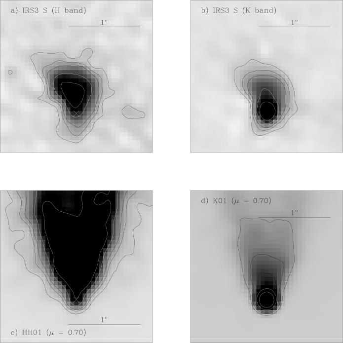
Firstly, a reasonable match to the K band image for IRS3 S was found, which is given by the fiducial model used in the grid seen at an inclination angle of (Fig. 2c). A zoom into the central of this model is shown in Fig. 10d. The H band image for the fiducial model using the opacity = (c.f. Sect. 2) appears to be too extended (see Fig. 8b). Other combinations of inclination angle and mass infall rate were also too extended since the optical depth at H was always too high. Therefore, a shallower opacity law was used in an attempt to achieve a better fit to the IRS3 S H band image. The new value used for at H was which corresponds with an opacity law () with between and (instead of the previous value of ). The exponent 1.3 was chosen to yield an opacity law slightly flatter than than the inferred from studies on the interstellar extinction in the near-IR (e.g. He et al. 1995). The model using the shallower opacity law (HH01 in Table 1) is shown in Fig. 10. It can be seen that this law still yields a rather extended nebula compared with the H band image of IRS3 S. A shallower opacity law than the one given by Draine & Lee (1984) has been used by other authors (e.g. Lucas & Roche 1998) to explain the small variation with wavelength of reflection nebulae in low mass YSOs. This is possibly due to a different dust composition or grain size distribution in the circumstellar matter of YSOs than in the interstellar medium. Another possible explanation relies on the fact that speckle imaging acts as a spatial filter for diffuse extended features of the same order and larger than the seeing. Therefore, even if the nebula in the H band was extended for a few arcseconds, the reconstructed speckle image would only pick up the structure closer to the nebula peak, which is dominated by the high spatial frequencies. It may also be the case that the envelope density distribution is truncated at a distance of from the central source, causing both H and K images to have the same extent.
Even though a reasonably good fit was found to the K band speckle image of IRS3 S, the synthetic nebula shows some differences with respect to the observed nebula. In particular, the observed nebula departs clearly from the axi-symmetry, probably due to foreground extinction or the presence of a clumpy envelope. Besides, the brightness of the synthetic nebula (Fig. 10d) drops faster near the star than in the case of the observed nebula (Fig. 10b). Further out, at from the star, the brightness of the synthetic nebula appears to drop more smoothly than observed in IRS3 S. The sub-arcsecond nebula is the inner region of a large reflection nebula (with a diameter of ) that is seen in the near-IR seeing limited images of Mon R2 IRS3 (see Aspin & Walther 1990; Yao et al. 1997). The large scale nebula is a halo of reflected light around the whole cloud but its polarisation pattern indicates enhanced scattering along an axis that coincides with the sub-arcsecond nebula axis (PA ) .

To investigate if the model that matches the sub-arcsecond morphology of IRS3 S fits the outer part of the reflection nebula, the outer radius of the fiducial model was doubled while the mass infall rate was slightly reduced to to keep a K band optical depth of 8 at an inclination of . The profile along the cavity axis for this model was compared with the profile for the K band reconstructed image of IRS3 S and with the profile along the same direction for the reflection nebula studied by Aspin & Walther (1990). This comparison is shown in Fig. 11. The data for the large scale nebula were taken from the flux-calibrated contour map shown in Fig. 3 of Aspin & Walther (1990). The error bars correspond to half of the contour level separation in their map (). The data points for the observed sub-arcsecond nebula were calculated from a 02 wide line along the cavity axis passing through the star in IRS3 S on the normalised speckle image. The zero point offset for the magnitude scale was calculated by assigning a K magnitude of 6.6 (obtained from the 2MASS survey) to the total number of counts within an aperture of radius 25 that included both IRS3 N and S. The statistical error in the surface brightness is .
The profile for the model was calculated from 02 wide line along the cavity axis in the synthetic image normalised to the brightness peak. The zero point offset for the magnitude scale was chosen such that it yields the same brightness at the peak as the flux-calibrated speckle data.
Figure 11 shows that there may be a discrepancy of at least between the data from Aspin et al. and the speckle data. A possible explanation is that speckle imaging filters out any background smooth emission, and hence less counts in the speckle image than in the seeing limited image of Aspin et al. appear to account for the same flux. The profiles plotted in Fig. 11 show that the model predicts emission from the outer parts of the nebula (at a distance from the star ) that is about 2 magnitudes brighter than it is observed. This may be caused by a drop in the density distribution of IRS3 at a radius AU that is not included in the models (cf. Figs. 10a and b).
Willner et al. (1982) estimated an optical depth for the silicate absorption feature at of = 4.30, using a aperture centered at Mon R2 IRS3. The same value is also inferred from the ISO spectrum of the region (Jackie Keane private comunication). This value can be used as an estimate of the total extinction (foreground and through the envelope) towards IRS3 S. This leads to an optical extinction of (Draine & Lee 1984) . This corresponds with an extinction in the K band = 8.6 mag (i.e ) using the reddening law of He et al. (1995), which is in good agreement with the K band optical depth for the fiducial model ().
We found that the colour of IRS3 S is redder than the colour of any of the model images. This is probably caused by the fact that we used the SED of an OB main sequence star to define the input spectrum. However, it is very likely that the illuminating source has an excess in the K band due to the presence of a possible accretion disc, and/or hot dust near the star. The inclusion of an excess of K band photons in the input spectrum may solve the discrepancy between the observed and modeled colours. High resolution photometry at longer wavelengths is required to constrain the input spectrum in the simulations.
5 Conclusions
Radiative transfer Monte Carlo simulations have been used to investigate the density distribution in massive YSOs at scales where the outflow is generated. The assumed density distribution consists of a central massive star within a flattened dusty envelope, with a cavity and an inner optically thick disc. It is found that envelopes with density distributions corresponding to typical mass infall rates of seen at an inclination angle of approximately reproduce the morphology and extension of the sub-arcsecond nebulae observed in massive YSOs. The inclination angle can be constrained by the measurement of the contrast between the approaching and the receding nebular lobe, although observations with a high dynamic range are required (e.g. adaptive optics). The cavity opening angle is well constrained by the nebula opening angle. The simulations indicate possibly some constraints on cavity shape and radius at the equator, which could have implications for the initial angle of the outflow (e.g. jet, wide-angled, equatorial). However, higher resolution than provided by speckle imaging in 4m-class telescopes is needed to achieve better constraints of these two quantities. The models do not provide significant constraints on the flattening in the envelope or the size of the equatorial disc, which require direct observations with millimetre interferometry.
The Monte Carlo code was also applied to the near-IR sub-arcsecond reflection nebula seen in Mon R2 IRS3 S. An envelope with a mass infall rate of that includes a conical cavity with an opening angle of seen at an inclination angle of provides a reasonable match for the K band image. However, no set of input parameters was found that reproduces both the H and K band images of IRS3 S. An opacity law with an exponent (Draine & Lee 1984; Draine 1985) yields H band nebulae that are too extended with respect to the observations. This would also be the case for the observed interstellar extinction law (; He et al. 1995). A shallower opacity law () yields a better match to observed H band nebula, although still too extended. This indicates that the dust in the circumstellar envelope of massive YSOs may have a rather different optical properties to the dust that forms part of the interstellar medium. However, a truncated density distribution could also explain the data.
Overall, this work shows that future high resolution ( 005) high dynamic range () near-IR imaging has the potential to constrain the inclination angle and shape of the base of the outflow cavity. In turn, this could test hydrodynamic models of the interplay between the infall and outflow in massive YSOs.
Acknowledgements.
CA would like to thank to the Physics and Astronomy Department at Leeds University for their support. CA is also deeply grateful to Kapteyn Astronomical Institute for allowing him to use their facilities during the realization of this work. We would like to thank B. Whitney, the referee of this work, for her comments and suggestions.References
- Aspin & Walther (1990) Aspin, C. & Walther, D. M. 1990, A&A, 235, 387
- Bachiller et al. (1995) Bachiller, R., Guilloteau, S., Dutrey, A., Planesas, P., & Martin-Pintado, J. 1995, A&A, 299, 857
- Bally & Lada (1983) Bally, J. & Lada, C. J. 1983, ApJ, 265, 824
- Beuther et al. (2002) Beuther, H., Schilke, P., Sridharan, T. K., et al. 2002, A&A, 383, 892
- Bohlin et al. (1978) Bohlin, R. C., Savage, B. D., & Drake, J. F. 1978, ApJ, 224, 132
- Burrows et al. (1996) Burrows, C. J., Stapelfeldt, K. R., Watson, A. M., et al. 1996, ApJ, 473, 437
- Davis et al. (1998) Davis, C. J., Moriarty-Schieven, G., Eislöffel, J., Hoare, M. G., & Ray, T. P. 1998, AJ, 115, 1118
- Delamarter et al. (2000) Delamarter, G., Frank, A., & Hartmann, L. 2000, ApJ, 530, 923
- Draine (1985) Draine, B. T. 1985, ApJS, 57, 587
- Draine & Lee (1984) Draine, B. T. & Lee, H. M. 1984, ApJ, 285, 89
- Drew & Proga (2000) Drew, J. E. & Proga, D. 2000, New Astronomy Review, 44, 21
- Drew et al. (1998) Drew, J. E., Proga, D., & Stone, J. M. 1998, MNRAS, 296, L6
- Eislöffel (2000) Eislöffel, J. 2000, A&A, 354, 236
- Fischer et al. (1994) Fischer, O., Henning, T., & Yorke, H. W. 1994, A&A, 284, 187
- Fischer et al. (1996) Fischer, O., Henning, T., & Yorke, H. W. 1996, A&A, 308, 863
- He et al. (1995) He, L., Whitte t, D. C. B., Kilkenny, D., & Spencer Jones, J. H. 1995, ApJS, 101, 335
- Henning et al. (2000) Henning, T., Schreyer, K., Launhardt, R., & Burkert, A. 2000, A&A, 353, 211
- Hoare (2002) Hoare, M. G. 2002, in The Earliest Stages of Massive Star Birth. ASP Conference Proceedings, Vol. 267. Edited by Paul A. Crowther, 137
- Hoare et al. (1994) Hoare, M. G., Drew, J. E., Muxlow, T. B., & Davis, R. J. 1994, ApJL, 421, L51
- Hoare & Muxlow (1996) Hoare, M. G. & Muxlow, T. B. 1996, in ASP Conf. Ser. 93: Radio Emission from the Stars and the Sun, 47
- Kenyon et al. (1993) Kenyon, S. J., Whitney, B. A., Gomez, M., & Hartmann, L. 1993, ApJ, 414, 773
- Kurucz (1979) Kurucz, R. L. 1979, ApJS, 40, 1
- Lazareff et al. (1990) Lazareff, B., Monin, J., & Pudritz, R. E. 1990, ApJ, 358, 170
- Lucas (2003) Lucas, P. W. 2003, JQSRT, 79, 921
- Lucas & Roche (1996) Lucas, P. W. & Roche, P. F. 1996, MNRAS, 280, 1219
- Lucas & Roche (1997) Lucas, P. W. & Roche, P. F. 1997, MNRAS, 286, 895
- Lucas & Roche (1998) Lucas, P. W. & Roche, P. F. 1998, MNRAS, 299, 699
- Maeder & Behrend (2002) Maeder, A. & Behrend, R. 2002, A&ASS, 281, 75
- Marti et al. (1993) Marti, J., Rodriguez, L. F., & Reipurth, B. 1993, ApJ, 416, 208
- Masson & Chernin (1994) Masson, C. R. & Chernin, L. M. 1994, in ASP Conf. Ser. 65: Clouds, Cores, and Low Mass Stars, 350
- Mathis et al. (1977) Mathis, J. S., Rumpl, W., & Nordsieck, K. H. 1977, ApJ, 217, 425
- Mundt & Ray (1994) Mundt, R. & Ray, T. P. 1994, in ASP Conf. Ser. 62: The Nature and Evolutionary Status of Herbig Ae/Be Stars, 237
- Osterloh et al. (1997) Osterloh, M., Henning, T., & Launhardt, R. 1997, ApJS, 110, 71
- Preibisch et al. (2002) Preibisch, T., Balega, Y. Y., Schertl, D., & Weigelt, G. 2002, A&A, 392, 945
- Reipurth et al. (1997) Reipurth, B., Bally, J., & Devine, D. 1997, AJ, 114, 2708
- Ridge & Moore (2001) Ridge, N. A. & Moore, T. J. T. 2001, A&A, 378, 495
- Schertl et al. (2000) Schertl, D., Balega, Y., Hannemann, T., et al. 2000, A&A, 361, L29
- Shu et al. (1994) Shu, F., Najita, J., Ostriker, E., Wilkin, F. andRuden, S., & Lizano, S. 1994, ApJ, 429, 781
- Terebey et al. (1984) Terebey, S., Shu, F. H., & Cassen, P. 1984, ApJ, 286, 529
- Tomisaka (1998) Tomisaka, K. 1998, ApJL, 502, L163
- Torrelles et al. (1996) Torrelles, J. M., Gomez, J. F., Rodriguez, L. F., et al. 1996, ApJL, 457, L107
- Ulrich (1976) Ulrich, R. K. 1976, ApJ, 210, 377
- Wang et al. (2003) Wang, H., Yang, J., Wang, M., & Yan, J. 2003, AJ, 125, 842
- Whitney & Hartmann (1992) Whitney, B. A. & Hartmann, L. 1992, ApJ, 395, 529
- Whitney et al. (1997) Whitney, B. A., Kenyon, S. J., & Gomez, M. 1997, ApJ, 485, 703
- Whitney & Wolff (2002) Whitney, B. A. & Wolff, M. J. 2002, ApJ, 574, 205
- Willner et al. (1982) Willner, S. P., Gillett, F. C., Herter, T. L., et al. 1982, ApJ, 253, 174
- Wolf et al. (2002) Wolf, S., Voshchinnikov, N. V., & Henning, T. 2002, A&A, 385, 365
- Wolfire & Cassinelli (1986) Wolfire, M. G. & Cassinelli, J. P. 1986, ApJ, 310, 207
- Yao et al. (1997) Yao, Y., Hirata, N., Ishii, M., et al. 1997, ApJ, 490, 281