Position-sensitive detector for the 6-meter optical telescope
The Position-Sensitive Detector (PSD) for photometrical and spectral observation on the 6-meter optical telescope of the Special Astrophysical Observatory (Russia) is described. The PSD consists of a position-sensitive tube, amplifiers of output signals, analog-to-digital converters (ADC) and a digital logic plate, which produces a signal for ADC start and an external strob pulse for reading information by registration system. If necessary, the thermoelectric cooler can be used. The position-sensitive tube has the following main elements: a photocathode, electrodes of inverting optics, a block of microchannel plates (MCP) and a position-sensitive collector of quadrant type. The main parameters of the PSD are the diameter of the sensitive surface is 25 mm, the spatial resolution is better than 100 m in the centre and a little worse on the periphery; the dead time is near 0.5 s; the detection quantum efficiency is defined by the photocathode and it is not less than 0.1, as a rule; dark current is about hundreds of cps, or less, when cooling. PSD spectral sensitivity depends on the type of photocathode and input window material. We use a multialkali photocathode and a fiber or UV-glass, which gives the short- wave cut of 360 nm or 250 nm, respectively.
Key Words.:
PSD; photocathode; MCP; charge-sensitive amplifier1 Introduction.
The light fluxes from the celestial objects under study are so weak that even in observations with large telescopes a photon falls on one element of the image far from every second. For such fluxes a maximum quantum efficiency is an obvious requirement to the detector. And in our investigations of relativistic objects for the purpose of search for variability of quantum fluxes up to microseconds it is necessary to analyse the time series of quantum registration moments. In this case the variability manifests itself in the short-wave region of the optical spectrum. These requirements defined use of position-sensi- tive detectors (PSD) in observations with our 6-m op- tical telescope. The PSDs represent vacuum photoelectron tubes with microchannel amplification and position-sensitive collectors. The advantage of this type of detectors is that the sensitivity of their photocathodes is sufficiently high, and the most important is the fact that there is a possibility of detection of quantum arrival times with an accuracy up to dozens of picoseconds in prospect. This fact makes the PSD suitable for investigations of relativistic objects and we are working in this field now.
2 Design of the PSD and duties of its main components.
A schematic view of the detector is given in Fig.1.
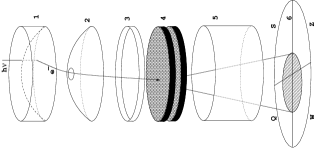
The numbers designate the following: 1 - input optical disk with a photocathode on its internal surface; 2 - anode (by changing its voltage one can change the electro-optical magnification within 0.5-1.5); 3 - antidistortion ring; 4 - stack of microchannel amplification formed by three or two microchannel plates (MCP); 5 - metal rings which create an electrostatic field of such a configuration which provides a maximum possible working field at minimum geometrical distortions and charge losses at the periphery; 6 - position-sensitive collector of quadrant type. This collector has an advantage over a wedge and strip ones [T. Arkhipova et al.] in considerably smaller interelectrode capacitances. This permits one to diminish the amplification of the MCP-stack and extend the range of operation of the detector towards greater load. A lower capacitance will lead to decrease of noises of the amplifiers, which gives an improvement of spatial resolution. The disadvantage of the quadrant collector is the deterioration of the resolution at the periphery; however it is of minor importance when observing star-like objects because the object observed can be placed in the centre.
3 The electronic schemes and design of the photosensitive device.
The important components of the device are signal amplifiers of the PSD collector. We use integrated curcuit amplifiers of The National Centre of High Energy Physics (NCHEP) [O. Dvornikov et al]. A computer modeling with allowance made for the PSD parameters having a quadrant collector made it possible to choose an optimum value of the time of shaping of 0.25s, an equivalent noise of no more than 600 electrons was provided. With an amplification of the MCP stack by several units 106, the statistical noise for the central area of the collector is equal approximately to the same value and this allows an image format no smaller than 300x300 to be obtained. Such a resolution complies with the astrophysical requirements. The amplifier is made like charge-sensitive ones (CSA) and consists of two sections [V. Debur, A. Solin]. The first section is intended for the transformation of the input charge to the output voltage with a decay time of 2.5s. When passing to the second section the pulse is shortened to a value of 0.25s with quasi-Gaussian shaping. The amplifier provides a transformation coefficient of 30 mV/fC necessary for operation with the analog to digital converters (ADCs) having an input signal range of 2 V, with the nominal gain of the MCP stack. The amplifiers are not overloaded and make it possible to register adjacent pulses separated by the time a few times as short as the pulse duration. For digitization of signal we use 10-digit ADCs of type AD871. The equivalent noise charge of the CSA equal to 600 electrons corresponds to a value of about 3 mV at 30mV/fC, that is the ADCs provide the measurements of signals with sufficient accuracy. The check of the registration channels by way of supplying test signals to the CSA inputs yielded a FWHM value of about 2-3 channels for the each of four amplifiers. The timing channel of the detector is needed for the formation of the start pulses of the ADCs and production of strobe pulses for recording the time moments of the registered quants. The amplifier and discriminator connected to the output plate of the MCP stack are also designed by using of ICs of the NCHEP. The whole description of electronics questions is given in [V. Debur, A. Solin ]. The external view of the device is displayed in Fig. 2.
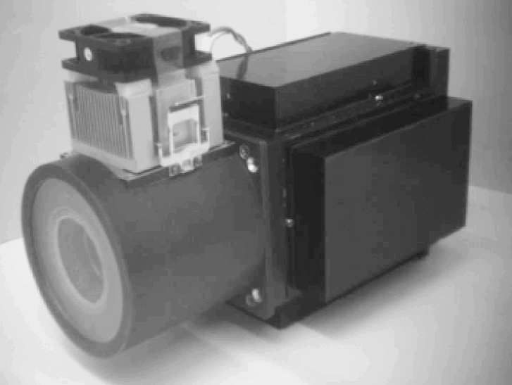
The entrance window covers the space around the PSD, which is cooled by a single-stage thermoelectrical refrigerator. The heat from the hot surface is withdrawn with the help of the processor cooler. The housing of the PSD contains the PSD and amplifiers. The side compartments hold the high voltage supply resistors of the PSD, the ADCs and auxiliary plates. At the back are located plug-and- sockets for connection of power supply and output signals to the CAMAC-crate in which the modules of the system Quantochron and necessary service modules are placed. The overall dimensions of the device are 140x180x290 (mm).
In development of the photosensitive device it was required that it should be operated with the available registration system Quantochron [A. Zhuravkov et al]. The output information must represent 16-digits words with TTL-levels and strobe-pulse for measuring the time moments.
4 Data registration
The PSD operates as part of the acquisition complex incorpora ting also a device for receiving photocount flux codes, a computer for control and data acquisition, which is located in the local net with the computer of the astronomer- operator. The functional diagram of the photometrical complex is shown in Fig. 3.
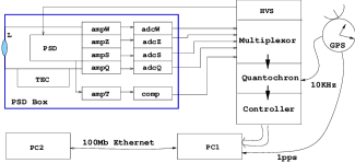
The flux of photocounts from the PSD must be transferred to the computer data storage in the form it is received by the detector, as counts of registrat ion time of all the quanta and their coordinates, the rate of count arriving must be up to 100 000 quants/s. For this purpose, we use the time-code converter Quantochron [1]. Primarily it was designed for registration of the data flows which have a 16-bit coordinate field (265x256 elements). The application of the PSD with a quadrant collector and the use of 10-bits ADC demanded extension of capacity up to 40 bits, this is why as a temporal measure we use a multiplexor which disconnects each arriving 40-bits photocount into three sequential messages: 8, 16 and 16 bits. The 8 bits in the first message are used for auxiliary information.
5 Characteristics of the PSD.
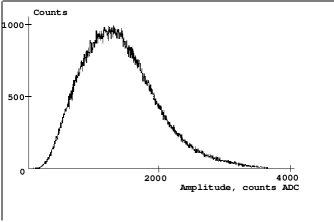
The single electron pulses distribution of the detector has been derived by summation of all 4 channels and is presented in Fig. 4. Despite the fact that all individual channels have a nearly exponential distribution, the common distribution has a well defined peak, which allows a conclusion to be made that the acquisition system registers practically all the pulses. Nevertheless the branch from the side of small amplitudes impairs the spatial resolution at the periphery. The shape of the amplitude distribution is preserved at count rates up to 100 cps and above, the photocathode being uniformly illuminated. With point-like illumination, like the star image, at count rates higher than 10 cps the images of stars begin to differ from gaussian by a flatter peak and then begin to acquire a dip at the centre.
The characteristics of the spectral response of the photocathodes of two different types are presented in Fig. 5.
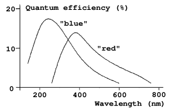
The photocathode of the ”red” PSD is on a fiber disc of ordinary glass, while the photocathode of the ”blue” PSD is on a disc of the UV glass. The latter was made to achieve maximum sensitivity in the ultraviolet region. The presented types of the photocathodes largely differ in thermoelectron emission current. One can work with the ”blue” photocathode at a room temperature without cooling. It has about 50 electrons/s from the whole area, whereas the ”red” photocathode has about 15000 electrons/s at a room temperature and it is necessary cooling down to C.
Figure 6 shows 512x512 elements detector field with image of emitting points got as a result of photons coordinates binning.
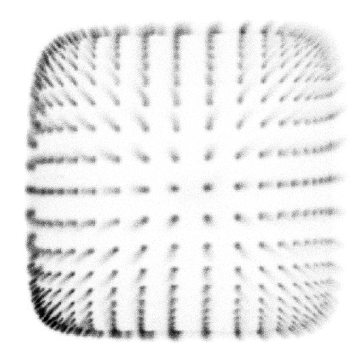
Reduction of collected data is performed for each received photon separately and is based on knowledge of counts distortion mechanisms related to electronic clound formation geometry.
Some of this process features are:
-
•
Different scales of image for different integral charge levels of each photo count - for lower charges image scale is bigger than for higher ones. Functional shape of inverse charge value and point coordinates for one physical source is nearly linear. Such scale dependency correction makes it possible to increase image sharpness over the whole detector field.
-
•
Spherical image distortion may be successfully compensated by tangential correction.
-
•
Cross-like central condensation on flat-field image is due to superposition of electronic density gap in electronic clouds centres and dielectric gap between detector quadrants and may be corrected using arctangent coordinates transformation. This transformation must also take into account non-perpendicularity of collector quadrants edges.
Fig. 7 shows the result of applying these transformations to image.
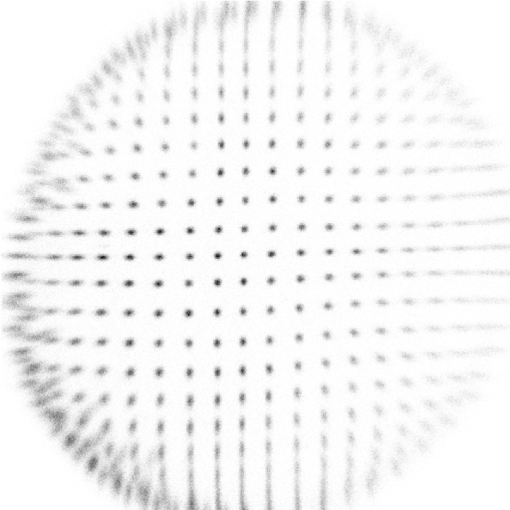
Residual non-singular central condensation may be compensated by polynomial corrction.
The FWHM of the point spread function at the centre is less than 100 m. Such quality is quite satisfactory since the size of the stars in our optical system is generally 400-500 m, and only on rare nights it may diminish to 150 m. The field that we observe usually contains one investigated star. At the present time we are working over the increase of information capacity of images being acquired. For this purpose, we use polarization and light-dividing elements which allow observation of the object and comparison star simultaneously in one field, in different polarization and spectral intervals. In so doing, the number of object images increases to eight [V. Plokhotnichenko et al].
6 Prospects of development of the PSD at SAO.
The improvement of the spatial resolution can be attained through increasing the gain of the MCP stack and may come quite closely to the value defined by the size of the MCP channels, about 15 m and less. The requirements to the noise of the charge sensitive amplifiers become more stringent. The improvement of the temporal resolution can be brought to less than nanosecond if required. However, in our investigations it makes no sense to make it an order of magnitude better than the dead time of the system. And we evaluate the reserve of improvement of the dead time as nearly an order, since by the present time integral circuits of multichannel amplifiers capable of operating at shaping times of about 100 ns have been developed. The increase in the sensitive area diameter to 40 mm seems to be relatively simple, but the increase up to 80 mm is possible only with the use of electro-optical diminishing in the input camera. The quantum efficiency depends on the quality of the photocathode, and its possible to have almost 40% at maximum. The dark current must be much lower than the night sky background, but the cooling of the photocathode is a relatively simple task. The increase in the upper count rate for a point image presents a problem, however, it is possible by nearly an order of magnitude for spread images provided that the dead time is decreased. It appears worth-while for the authors to pass to a multielement collector, for instance, 8-elements hexagonal or up to 19-elements. The progress achieved in integral circuits and computers makes possible registration and reduction of signals from such collectors.
Acknowledgements
This investigation was supported by the Russian Ministry of Science, Russian Foundation of Basic Researches (grant 01-02-17857), Federal Program ”Astronomy” and INTAS (grant 96-542).
References
- (1) T. Arkhipova, V. Debur, G. Kuptsova, A. Mechetin, M. Pakhomov, M. Smirnova, Instruments and Experimental Techniques, 2 (1993) 146.
- (2) O. Dvornikov, A. Solin, V. Chekhovskij, Chip news, 11-12 (1997) 28.
- (3) A. Zhuravkov, A. Pimonov, V. Plokhotnichenko, Bull. Spec. Astrophys. Obs., 37 (1994) 159.
- (4) V. Debur, A. Solin, Report of SAO RAS and NCHEP, 288 (2002).
- (5) V. Plokhotnichenko, G. Beskin, V. Debur, A. Panferov, I. Panferova, Proceedings of the PSD-6 conference.