Meeting the Optical Requirements of
Large Focal-Plane Arrays
Abstract
Technological advances will allow the placement of many Terahertz detectors at the focal plane of a single telescope. For a telescope of a given diameter and wavelength of operation, there is a limit to the number of usable detectors imposed by diffraction and optical aberrations. These effects can be ameliorated through an optical design where the magnification of the telescope’s secondary mirror is small and the detector package is therefore located near the secondary mirror. A field mirror can be used to flatten the image, and the focal reducer which matches the detector to the telescope can also provide an image of the aperture for placement of filters and stops. A design concept is presented for the South Pole Telescope which comprises a 10 meter diameter off-axis paraboloidal primary mirror, a Gregorian secondary mirror, a tertiary chopper, dewar widow, Lyot stops, band-pass filter, and space behind the focal plane for cryogenics. The telescope is bilaterally symmetric, and all apertures are unblocked. The field of view is one degree in diameter, so this telescope can feed an array of several detectors at Terahertz frequencies.
cmr12 scaled 900
I Introduction
The South Pole Telescope (SPT) is a 10 m diameter millimeter- and submillimeter-wave telescope which has been approved for construction at Amundsen-Scott South Pole Station. It is funded by the National Science Foundation Office of Polar Programs, and the participating institutions are the University of Chicago, the Smithsonian Astrophysical Observatory, the University of California at Berkeley, Case Western Reserve University and the University of Illinois. Work on the telescope design is in progress. Construction is expected to begin by the end of 2003.
The initial project planned for this telescope is a large-scale survey covering many thousands of square degrees of sky, searching for the Sunyaev-Zel’dovich effect from clusters of galaxies at all redshifts. This search will be done with a focal-plane array of bolometers operating at 2 mm wavelength. The diffraction-limited beamsize at that wavelength (with conservative illumination of the primary mirror) will be about an arcminute, an angular size chosen to be comparable to the size of clusters at cosmological distances. The focal plane array will have about 1000 detectors; making an array of this size is thought to be possible using current bolometer technology (Gildemeister, Lee, & Richards (2000)). Such a large number of independent beams of arcminute size requires a field of view about a degree in diameter. This paper describes a design for the telescope optics which will feed 1000 beams at . The significance of this work for Terahertz technology is the serendipitously good quality to which this design can be optimized: the optics are sufficiently well-corrected that they will work at and feed an array containing more than 30,000 detectors.
II Optical Design Considerations
Submillimeter-wave telescopes have different design constraints than optical telescopes. This is fortunate, because 10 meter class visual-wavelength telescopes have fields of view less than 0.2 degree in diameter, much smaller than the design requirement of the SPT. Since diffraction is more important at submillimeter wavelengths, the allowable size of optical aberrations is larger, and if the aberrations are balanced across the field of view, that field of view can be large (Stark (2000); Stark et al. (1998)).
The SPT design is driven by its intended use as a cosmic microwave background instrument. It must have the lowest possible thermal emission from the telescope, the lowest possible variations in the residual thermal emission that remain, and the smallest possible spillover of the beam onto the ground and surrounding structures. This means that the optical path should have
-
•
no aperture blockage anywhere in the system;
-
•
conservatively illuminated optics;
-
•
no warm lenses.
The optical train must therefore consist almost entirely of off-axis mirrors, with the possible exception of a lens or lenses which are inside the cryogenic dewar and cooled to low temperatures. Fortunately, machined aluminum mirrors are near-perfect at millimeter and submillimeter wavelengths; the addition of a mirror to the optical train does not cause significant degradation of the system and many mirrors can be used. Furthermore, it is possible to fabricate mirrors of arbitrary shape.
The cryogenic dewar brings its own set of optical requirements:
-
•
the dewar window must be small enough that it can be constructed from low-loss materials and not implode;
-
•
there should be a Lyot stop—an image of the primary mirror inside the dewar—for placement of a cold aperture which prevents the detectors from seeing beyond the edges of the optical elements;
-
•
there must be a low-pass filter near the dewar window to block infrared radiation;
-
•
the filter diameters must be small enough to be constructible—also, filters do not work at large angles of incidence.
It is best that the dewar not be too large, since the weight of the dewar increases and the ease of handling decreases as the enclosed volume goes up. The Lyot stop should therefore be close to the detector, since both must be kept cold. Mirrors can be warm and need not be inside the dewar. The detectors also impose their own requirements:
-
•
there must be a band-pass filter to determine the wavelength of operation;
-
•
the ratio f/D should be a uniform, fixed value (1.3 in this case) for each point in the image;
-
•
the chief ray at each detector should be perpendicular to the surface of best images; that surface should be flat;
-
•
all detectors should be identically illuminated.
III The Problem of the Lagrange Invariant
The design difficulties inherent in a wide-field system can be appreciated by consideration of the Lagrange invariant. One way of expressing this quantity is , where at a plane intersecting the optical path, is the area illuminated by the envelope of all rays through the system, and is the solid angle subtended by the frustum of those rays. This quantity is conserved along the optical path. Evaluating at the aperture of the SPT telescope, . If the beam passes through a small aperture some place in the optical chain, for example at a 200 mm diameter dewar window, then the beam there must converge at a fast angle. It is impossible to pass the beam through a 50 mm diameter aperture, because the included angle of the beam would need to be . The optical path will necessarily consist of large optical elements, of order a meter in diameter, and the beam will spread rapidly between elements, requiring that the separation between optical elements is comparable to their size.
Accommodating a large Lagrange invariant is awkward in conventional Cassegrain or Gregorian telescope designs, because the small size of the secondary mirror and the large distance between it and its focus make the subsequent optics gigantic. The magnification of a telescope’s secondary mirror, , is the distance from the mirror center to the far focus divided by the distance from the mirror center to the near focus. (By definition, the sign of is negative for Gregorians and positive for Cassegrains.) The secondary mirror magnification in on-axis Cassegrain or Gregorian telescopes is typically . Let is the focal length of the primary mirror. In a 10 meter class telescope, . The size of the image at the Cassegrain focus is where is the field-of-view. If , , so that any tertiary mirror in the vicinity of the the Cassegrain or Gregorian focus must be about 3 meters across—an awkwardly large size. The way around this is to make small, closer to 3 than 25.
If is small, the Cassegrain or Gregorian focus is not far from the secondary mirror, and the subsequent optics and the detector will necessarily be located between the secondary and the primary. Such a position can easily be accommodated in an off-axis telescope design, where the detector dewar and its ancillary optics can be placed in the secondary mirror support structure, out of the way of the primary beam. The National Radio Astronomy Observatory’s Green Bank Telescope is configured this way.
IV A Specific Design
In optical design, it is difficult to prove that something cannot be done—there are many clever tricks available to the optical designer, and much room for the exercise of ingenuity. It is, however, possible to show that something can be done through an example. What follows is a particular optical design that meets the criteria for the Sunyaev-Zel’dovich effect survey with the South Pole Telescope. This is one possible design out of many. It is not fully optimized and the South Pole Telescope will not be built exactly this way, but it is presented as a demonstration that a wide-field submillimeter-wave telescope is possible. Other designs can be found at http://www.tonystark.org. The important point for the development of Terahertz technology is the serendipitous result that this design exceeds the requirements for millimeter-wave work and is sufficiently well-corrected that it will work at Terahertz frequencies.
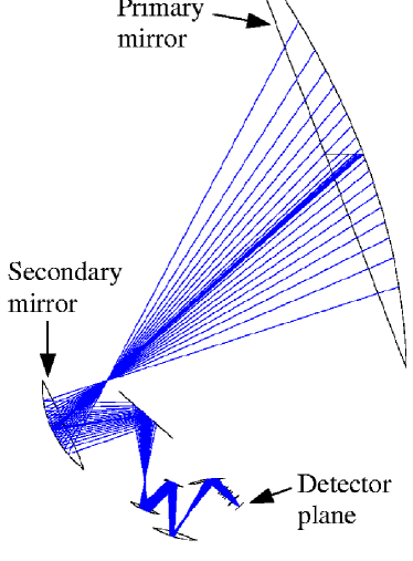
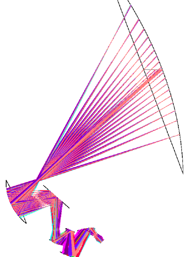
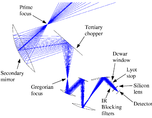
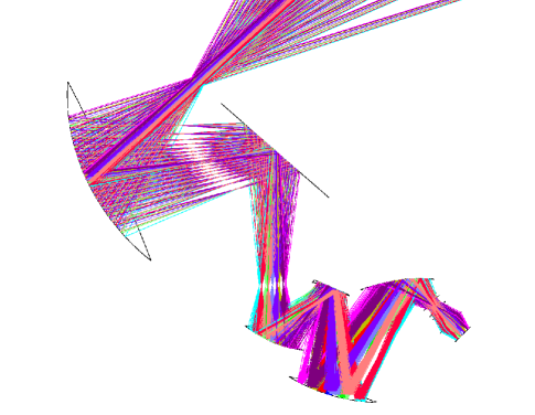
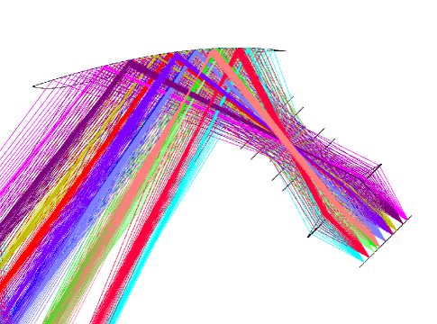
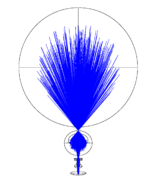
The figures show various aspects of a ZEMAX***ZEMAX is a trademark of ZEMAX Development Corporation of San Diego, CA computer model of an optical design called SPST214. In this design, the primary mirror is a 10 m diameter section of of a paraboloid with a 7 m focal length. The secondary is an off-axis piece of a prolate ellipsoid. Figure 1 is a view from the side, showing seven mirror surfaces, one lens, and the detector plane. Also shown are some rays from a source at the center of the field of view: note that all these rays come together at the prime focus, at the Gregorian focus, and at the detector. Figure 2 is the same view, but shows rays from twelve sources distributed over the one-degree-diameter field of view. Figures 3, 4 and 5 are details of Figures 1 and 2. Figure 6 shows the view from the front, as seen from the source being observed. Note that the secondary mirror is well out of the main beam from the primary mirror. The secondary mirror is 2330 mm wide by 1970 mm high. The tertiary mirror is flat, and will be used as a chopper. Note in Figure 4 that it is located near an image of the primary mirror. The surfaces of mirrors four through seven have arbitrary shapes—their only constraint is that they are bi-laterally symmetric about a vertical plane. From the dewar window to the detector, the optical elements are cylindrically symmetric about the chief ray of the center of the field of view.
As seen in Figure 5, the dewar window is 250 mm diameter and will likely be made of expanded plastic foam. The Lyot stop is an aperture 164 mm in diameter in the 4 K shield of the dewar. Infrared blocking filters are located behind the Lyot stop. The diameter of these filters can be as small as the Lyot stop, or, if they can be made larger, they could be located several centimeters behind it, which would allow the Lyot stop to block some of the photons scattered by the filter.
Silicon is an excellent material for a cold lens at millimeter wavelengths. The lens in this design is 350 mm in diameter and about 25 mm thick. A lens blank this size made of fairly high purity Silicon is readily obtained from several sources. The index of refraction of Silicon at 1.5 K is 3.38 (Loewenstein, Smith, & Morgan (1973)), and the loss through a lens this thick is a few percent or less, depending on the purity of the material. The lens is constrained to be plano-convex in order to facilitate anti-reflection coating. A more “bent” lens would work a little better in this application, but the anti-reflection coating might delaminate from a concave surface. The lens is slightly aspheric.
In the 150 GHz detector array to be used in the Sunyaev-Zel’dovich survey, the converging cones of rays will be intercepted by 1027 conical feedhorns drilled into an aluminum plate which is 200 mm in diameter and about 8 mm thick. There will be a short length of waveguide between each feedhorn and each bolometer detector, and that waveguide will encorporate a bandpass filter which will determine the bandwidth of the observations. The bolometers will be the “spiderweb” voltage-biased superconducting transition-edge sensor type (Gildemeister, Lee, & Richards (1999), 2000).
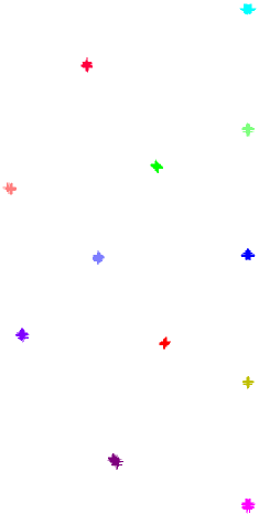
Figure 7 shows a spot diagram, where rays from twelve stars in a one degree diameter field of view are propagated to the detector, and the intersection of each ray with the detector plane is marked with a “+”. The important point for Terahertz technology is that the quality of the image at the detector plane is good enough to be used at Terahertz frequencies. The root-mean-square wavefront error at the detectors in this design is typically . This error could be reduced a factor of by relaxing the quality of the image of the aperture at the Lyot stop, which in this design meets stringent requirements imposed by its use as a microwave background anisotropy instrument. A wavefront error of is totally unsuitable for use at visual wavelengths, which is why wide-field visual wavelength telescopes are not designed this way, but the design begins to be usable at and would work well at . Providing it could be made, an appropriate Terahertz array could simply be substituted for the 150 GHz array currently being developed, and the optical system would work. At Terahertz frequencies, the 200 mm diameter image plane could accommodate tens of thousands of detectors.
V Conclusion
The South Pole Telescope, which is nearing the end of its design phase, will have an optical configuration capable of feeding several detectors at Terahertz frequencies. Such a detector array would be enormously powerful. Consider, for example, the problem of surveying an area of sky to find dusty protogalaxies. These are objects about one second of arc across, with an areal density of several hundred per square degree at a brightness of a few mJy at . The speed at which such objects can be found is proportional to
where is the total number of detectors (bolometer or heterodyne) in the telescope, is the total effective collecting area (regardless of whether it is arranged in one dish or many), is the pre-detection bandwidth, and is the effective system temperature adjusted for losses, atmospheric absorption and emission (Stark (2000)).
| Telescope | Relative Speed | ||||
|---|---|---|---|---|---|
| SPT | 20000 | 150 GHz | 200 K | 3750 | |
| ALMA | 160 | 4 GHz | 300 K | 46 |
Table 1 estimates the value of this figure of merit for the South Pole Telescope and for the Atacama Large Millimeter Array (ALMA), and shows that the SPT with a large bolometer array would be about 80 times faster than the ALMA at detecting objects in survey fields. Of course the ALMA has much higher angular and frequency resolution, and therefore shows a detailed picture. The SPT will be to the ALMA what a Schmidt camera is to a large visual-wavelength telescope—the means of detecting the objects to be studied. All that is needed is the technological development of large detector arrays.
I thank Nils Halverson, Adrian Lee, and William Holtzapfel for suggesting the use of a Silicon lens in the design. This material is based upon work supported by the National Science Foundation under Grant No. OPP-0130612.
References
- Gildemeister, Lee, & Richards (1999) Gildemeister, J., Lee, A., & Richards, P. 1999, Appl. Phys. Lett., 74, 868
- Gildemeister, Lee, & Richards (2000) —. 2000, Appl. Phys. Lett., 77, 4040
- Loewenstein, Smith, & Morgan (1973) Loewenstein, E. V., Smith, D. R., & Morgan, R. L. 1973, Appl. Opt., 12, 398
- Stark (2000) Stark, A. A. 2000, in Proceedings of SPIE, Vol. 4015, Radio Telescopes, ed. H. R. Butcher, 434
- Stark et al. (1998) Stark, A. A., Carlstrom, J. E., Israel, F. P., Menten, K. M., Peterson, J. B., Phillips, T. G., Sironi, G., & Walker, C. K. 1998, in Advanced Technology MMW, Radio and Terahertz Telescopes, Vol. 3357 (Proceedings of SPIE), 495–506, astro-ph/9802326