A Cosmic Microwave Background Radiation Polarimeter Using Superconducting Bearings
Abstract
Measurements of the polarization of the cosmic microwave background (CMB) radiation are expected to significantly increase our understanding of the early universe. We present a design for a CMB polarimeter in which a cryogenically cooled half wave plate rotates by means of a high-temperature superconducting (HTS) bearing. The design is optimized for implementation in MAXIPOL, a balloon-borne CMB polarimeter. A prototype bearing, consisting of commercially available ring-shaped permanent magnet and an array of YBCO bulk HTS material, has been constructed. We measured the coefficient of friction as a function of several parameters including temperature between 15 and 80 K, rotation frequency between 0.3 and 3.5 Hz, levitation distance between 6 and 10 mm, and ambient pressure between and 1 torr. The low rotational drag of the HTS bearing allows rotations for long periods of time with minimal input power and negligible wear and tear thus making this technology suitable for a future satellite mission.
I Introduction
Superconducting bearings are often considered one of the major uses of bulk high-temperature superconductor (HTS), and considerable development effort of such bearings has occurred since the discovery of HTS [1]. HTS bearings are characterized by very low drag torque. This, together with stiffness and damping against perturbations from equilibrium have led to investigations of their use in flywheel energy systems [2]-[6], a lunar telescope [7], sensitive gravimeters [8], and as a sensitive detector of gas pressure [9]. Here we present a design for a cosmic microwave background (CMB) radiation polarimeter that is based on levitating a rotating half wave plate by means of an HTS bearing.
There is intense scientific and popular interest in uncovering the physical conditions in the universe at epochs as close as possible to the big bang. Tremendous progress in this endeavor has been achieved already through detailed measurements of the cosmic microwave background radiation [10]. The CMB permeates the entire universe and has a black body spectrum with an equivalent temperature of 2.73 K [11]. Information about the spatial anisotropy in the intensity of the CMB, as measured by a number of recent experiments [12]-[15] has revealed that the universe is topologically flat [16]-[19] and has lent strong support to the idea that the universe has undergone a period of exponential growth, an ’inflation’, at about seconds after the bang [20]. By combining the data from CMB and other astrophysical measurements we can now determine that only 5% of the matter and energy density in the universe is made of ordinary electrons, quarks, neutrinos and photons, and that the rest is split into ’vacuum energy’ and a new form of ’dark matter’. Aside from their existence, very little is known about either the vacuum energy or the dark matter. CMB measurements have also helped to constrain the age of the universe to within about 10% accuracy and to construct a reliable scenario for its evolution.
The polarization of the CMB radiation field encodes new and valuable information about the early universe and an intense research effort has begun to discover and characterize the polarization signal. Detection of the polarization signal will enhance our confidence in the prevailing cosmological model and will provide more information about the properties of the constituents of the universe [21]. More importantly, the polarization signal seems to be the only direct probe of the inflationary epoch close to the big bang [22]. A detection of such a signal will provide strong supporting evidence for the concept of inflation and will illuminate the physical processes involved.
The polarization anisotropy of the CMB is expected to have two components, the ’scalar’ and ’tensor’ components [22]. The scalar component should have a magnitude of about a few , about a factor of 10 smaller than the 50 RMS temperature anisotropy. The tensor component, which has its origin in the inflationary epoch, is smaller by at least a factor of 100 compared to the temperature anisotropy. CMB receivers are just now reaching the sensitivity required to detect the scalar component. A high signal-to-noise ratio detection of the CMB polarization will require a combination of high sensitivity and strong rejection of systematic errors. An experimental approach that satisfies both of these requirements is to use bolometric detectors at the focal plane of an optical system that modulates the incoming polarization signal. Bolometers are the most sensitive detectors at the frequency range where the CMB is most intense [23]. Temporal modulation of the incoming signal and subsequent lock-in is a standard and powerful technique to separate small signals from noise. It is also an effective technique to reject systematic errors that appear at a frequency different from the signal modulation frequency.
The best technique currently available for modulating the polarization of the incident radiation is by turning a half wave plate (HWP). When a HWP is placed in the path of the incident light and turned at a rotation frequency , the polarization vector of the output radiation rotates at a frequency of . The radiation is then passed through a ’polarization analyzer’, for example a fixed polarizing grid, and is then detected. The signal recorded by the detector is modulated at a frequency of and standard lock-in techniques can be used to extract its magnitude. Although a rotating HWP has been used with many experiments, over a broad range of wavelengths [24]-[26] the challenge in adapting the technique to CMB polarimetry is coupling the rotation mechanism to bolometric detectors which have high sensitivity to microphonic noise. Standard mechanical rotation mechanisms, such as gears and bearings, have stick-slip friction which induce vibrations. The vibrations deposit mechanical energy in the detectors and cause wires to vibrate thereby inducing excess noise.
We have developed a magnetic bearing for use with polarization experiments that is based on magnetic levitation of a HWP above a high temperature superconductive (HTS) material. The apparatus is designed to fit in a balloon borne bolometric experiment MAXIPOL that will attempt to detect the scalar component of the CMB polarization [28]. The mechanism can be easily adapted to any polarization experiment and particularly for a future NASA satellite mission dedicated for detailed mapping of the tensor component of the CMB polarization. We describe the hardware in Section II, report on initial tests in Section III and summarize in Section IV.
II Description of Hardware
II-A Overview and Requirements
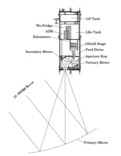
MAXIPOL consists of an array of 16 bolometric photometers coupled to a 3 mirror off-axis Gregorian telescope, see Fig. 1. The experiment is optimized for stratospheric balloon borne ( km) observations of the CMB. The high altitude significantly reduces photon noise and noise due to atmospheric fluctuations. The bolometers are maintained at a temperature of 0.1 K by means of an adiabatic demagnetization refrigerator [27]. The optical system consists of a 1.3 meter primary mirror and two additional mirrors that are maintained at liquid helium temperature.
Adapting a magnetic bearing system for a cryogenic balloon borne experiment poses a number of requirements on the particular implementation.
-
•
The HWP must be cooled to liquid He temperatures to reduce the optical load on the detectors.
-
•
The HWP must be located at the aperture stop of the optical system to eliminate a potential source of systematic error.
-
•
Characteristic rotation frequencies are Hz, limited by the msec response time of the bolometric detectors.
-
•
It should be possible to accelerate the rotor periodically with minimal friction or electro-magnetic interference.
-
•
The bearing system needs to be locked during periods of very strong accelerations, for example during launch or flight termination, and then released to begin operations. The latching mechanism needs to be remote-controlled.
-
•
The bearing system stiffness must be sufficiently high to operate through a range of tilt angles. Damping should be high to dampen oscillations that may occur during typical observing conditions.
-
•
All bearing properties must be stable over long periods of time.
II-B The HWP and Magnetic Bearing Mechanism
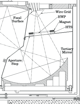
The HWP and its rotation mechanism are located at the aperture stop of the optical system, which is between the tertiary mirror and the focal surface of the system, see Fig. 2. A polarizing wire grid mounted at the entrance to the photometers transmits only one component of the incident polarization vector.
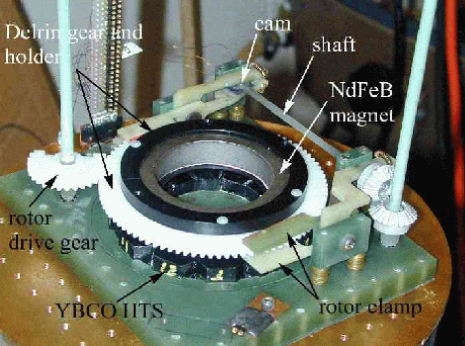
The HWP consists of a 3.2 mm thick z-cut sapphire disk with a radius of 2.54 cm which is mounted inside a permanent ring-shaped magnet. The magnet and the HWP are the rotor of a magnetic bearing that is levitated above a ring of YBCO HTS material. The sintered NdFeB magnet has an inside radius of 2.54 cm, an outside radius of 3.56 cm, thickness of 1.2 cm, and mass of 0.2 kg. It is polarized in the axial direction and has a remnance of Gauss and an energy product of Gauss-Oersted. The moments of inertia of the HWP and magnet are 83 and 1910 grcm2, respectively. A HWP holder, made of Delrin and with a gear at its outer circumference, holds the magnet/HWP combination together and is part of the rotor, see Fig. 3.
The magnet is held at an appropriate distance above a ring of HTS material which consists of 12 pieces of melt-textured YBCO [29]. The distance is a free parameter and is typically between 4 to 10 mm. Two clamps, each resembling a plier, hold the rotor in place during the cool-down of the system. A cryogenic stepping motor that drives a shaft and a pair of cams is used to open and close the clamps. The HTS material and the clamps are mounted on a G-10 board.
Rotation of the rotor is achieved by means of a half gear that is driven by a second stepping motor that is mounted outside of the cryostat. During cool-down the half gear and the gear at the outer circumference of the rotor are engaged. Once the system has cooled to 4 K, the clamps are opened and the half gear is turned with a pre-programmed acceleration.
If the need arises to re-rotate the rotor, the half-gear can be stepped slowly until it engages with the rotor, and the process repeats.
The axial spring constant at 77 K was measured to be 256 and 136 N/m for levitation distances of 8.6 and 10.7 mm, respectively. The corresponding resonant frequencies are about 5.5 and 4 Hz, respectively.
We tested all the mechanical components of the HTS bearing at liquid nitrogen, liquid helium and intermediate temperatures. We carried out spin-down measurements between and Hz to determine the coefficient of friction of the bearing at various temperatures, levitation heights, ambient pressures, and as a function of the magnetic field structure of the magnet. Measurements between 4.2 and 77 K were conducted in a liquid He cryostat (LHC) in which the stator was mounted on a 0.9 cm thick copper cold-plate. The temperature of the HTS was controlled with heating resistors and measured with a calibrated resistance and diode thermometers. The rotation rate was measured with an LED and a photodiode.
III Tests, Results and Interpretation
Another set of spin-down measurements at 77 K were conducted in a liquid nitrogen cryostat (LNC) with the apparatus described by Hull et al. [30]. This apparatus was designed to minimize energy losses due to eddy currents. The measurements with the LNC are summarized in Table I. In all measurements the rotor consisted of the magnet without the HWP.
We quantify the results of the spin-down measurements in terms of the coefficient of friction (COF) [30] given by
| (1) |
where sec2 is a rotor specific constant, and is the angular acceleration.
The angular acceleration can be a function of the frequency of rotation and temperature and we parameterize it as ([32])
| (2) |
The coefficient has been interpreted as the contribution of hysteresis to the angular acceleration and quantifies the contributions from eddy currents and ambient pressure [30]. If is non-zero then should be an exponential function of time.
| measurement | distance | Pressure | COF | ||
| ( mm) | (torr) | (rad/sec2) | (1/sec) | ||
| 1 | 8.6 | 0 | |||
| 2 | 8.6 | ||||
| 3 | 8.6 | ||||
| 4 | 9.5 | 0 | |||
| 5 | 10.7 | 0 | |||
| 6 | 10.7 | ||||
| 7 | 10.7 | ||||
| 8 | 10.7 | ||||
| 9 | 10.5 | 0 |
III-A COF Vs. Distance at 77 K: Hysteresis Losses
A comparison of lines 1,4,5 in Table I gives a comparison of the COF as a function of distance from the HTS with low ambient pressures, and negligible contribution from eddy currents.
The COF decreases as the distance between the rotor and stator increases. This decrease is correlated well with a decrease in the inhomogeneity of the axial component of the magnetic field as the distance from the magnet increases. We measured the strength of the magnetic field as a function of distance from the surface of the magnet. Measurements were taken at the inner, middle and outer radii of the magnet and every 10 degrees in azimuth. Since in these measurements the major contribution to the coefficient of friction is expected to be hysteresis loss in the HTS, we follow Hull et al [31] and quantify the inhomogeneity of the field by forming the quantity
| (3) |
where runs over the inner, middle and outer radii and
| (4) |
The variables are weights that are proportional to the ratios of elements of area as a function of radius. Figure 4 shows the quantity as a function of . The reduction in magnetic field inhomogeneity with distance is evident.

By interpolating the data of vs. height (Fig. 4) we plot in Fig. 5 the COF as a function of . The number of data points is small, nevertheless the data is suggestive of the linear relationship predicted by theory [31].

In order to reduce hysteresis losses and decrease the coefficient of friction we added shims in various locations on the surface of the magnet that pointed toward the HTS [31]. The shims were made of 25 - 150 m thick high permeability steel leaf. Measurements of the magnetic field at a distance of 7 mm away from the magnet gave less magnetic field inhomogeneity, as shown in Fig. 4. The COF was measured for a different shimming configuration (for which measurements of are not available) and gave the lowest COF measured with the LNC, see measurement 9.
III-B COF Vs. Pressure
Fig. 6 shows the magnitude of the coefficient as a function of ambient pressure. The measurement is a compilation of data from two levitation distances. The data show a decrease of with ambient pressure and are in broad agreement with those of Weinberger et al. [33], which suggest that becomes negligible at pressures below torr.

III-C COF Vs. Temperature
We used the LHC to measure the COF at levitation distances of 6 and 7.2 mm for various temperatures between 15 and 80 K and for frequencies between and 3.5 Hz. The magnet was released to levitate when the helium cold plate was at K and we have no information about the temperature of the magnet subsequently.
Measurements of the COF as a function of rotation frequency are shown in Figs 7 and 8. At low temperatures ( K) the data were consistent with a constant deceleration for most rotation frequencies with perhaps a slight increase in COF at frequencies below 1 Hz. At high temperatures, above about 60 K, the data show an increasing COF with frequency. The data at a levitation distance of 6 mm and 60 K show a transition between a constant COF above 1 Hz to a decreasing COF below 1 Hz.


Fig. 9 shows the COF as a function of temperature at a frequency of 1 Hz. A decrease in the COF by about a factor of is evident for both levitation heights.

Hull et al. [31] argue that the COF should be inversly proportional to the critical current in the HTS. Using data from Zeisberger et al.111The data of Zeisberger et al. [32] is for 0, 1, and 2 Tesla and shows a weak dependence on magnetic field strength. In our case the magnetic field is T and we use the 0 T data. [32] which give information about the critical current as a function of temperature we plot the COF as a function of in Fig. 10. Since we don’t have data about the critical current as a function of temperature for our HTS samples, it is premature to conclude that there is a disagreement between the data and the model.

IV Discussion and Summary
We have presented a working prototype for an HTS bearing for use with polarimeters that employ a HWP. The complete absence of stick-slip friction makes the magnetic bearing suitable for detector systems that are sensitive to microphonic excitation.
Our measurements indicate that with a readily available shimmed magnet and HTS, at the range of gas pressures expected in a liquid He cryostat and with no particular efforts to reduce eddy current losses we can expect a COF of (factor 2 less than the measured COF at 15 K due to shimming), which would give rise to an angular deceleration of about Hz/sec. If the rotor is set in motion and then slows down over a frequency range of 20 Hz, suitable for CMB observations between 21 and 1 Hz given the time constant of current bolometeric detectors, the bearing would need to be reset in motion once in 33 hours. Since re-setting the bearing in motion should take only a few minutes, the duty cycle of such a magnetic bearing system is close to 100%. The present design could be implemented in ground based or short duration balloon polarimeters.
A COF of is still two orders of magnitude larger than the smallest COF reported for the 300-400 gr mass category [1], indicating that a more careful design of the bearing and the cryostat in which it operates can provide uninterrupted rotation for more than 4 months. Even just a factor of 10 improvement in the COF would give a continuous rotation for a month, more than adequate for a long duration balloon mission.
With a slowly decelerating rotor the frequency where the polarization signal appears will also decrease. This could provide a powerful check on systematic errors, but could also complicate the analysis of the data. Rather than let the bearing slow down over a long period of time, it could be driven continuously with an induction or standard brushless motor [34]. If necessary a feed-back loop can be implemented to maintain constant speed. Because of the small COF, minimal power is required to drive such a motor and this approach appears most attractive for a future satellite polarimetry mission.
Despite of the success of our prototype more testing needs to be done to characterize the bearing performance. In particular it is essential to measure bearing oscillations, particularly at low temperatures where hysteretic damping is lower compared to 77 K, and the stability of the bearing parameters, e.g. stiffness, and levitation distance, should be tested over a long period of time.
References
- [1] J. Hull, ”Superconducting bearings,” Supercond. Sci. Technol., Vol. 13, pp. R1 - R14, 2000.
- [2] T. M. Mulcahy, J. R. Hull, K. L. Uherka, R. G. Abboud, and J. Juna, ”Test results of 2-kWh flywheel using passive PM and HTS bearings,” IEEE Trans. Appl. Supercond., vol. 11, pp. 1729 - 1734, June 2001.
- [3] S. Nagaya, N. Kashima, M. Minami, H. Kawashima, and S. Unisuga, ”Study on high- temperature superconducting magnetic bearing for 10 kWh flywheel energy storage system,” IEEE Trans. Appl. Supercond., vol. 11, pp. 1649 - 1652, June 2001.
- [4] T. Coombs, A. M. Campbell, R. Storey, and R. Weller, ”Superconducting magnetic bearings for energy storage flywheels,” IEEE Trans. Appl. Supercond., vol. 9, pp. 968 - 971, June 1999.
- [5] Y. Miyagawa, H. Kameno, R. Takahata, and H. Ueyama, ”A 0.5 kWh flywheel energy storage system using a high-Tc superconducting magnetic bearing,” IEEE Trans. Appl. Supercond., vol. 9, pp. 996 - 999, June 1999.
- [6] A. C. Day, M. Strasik, K. E. McCrary, P. E. Johnson, J. W. Gabrys, J. R. Schindler, R. A Hawkins, D. L. Carlson, M. D. Higgins, and J. R. Hull, ”Design and testing of the HTS bearing for a 10 kWh flywheel system,” Supercond. Sci. Technol., vol. 15, pp. 838 - 841, 2002.
- [7] E. Lee, K. B. Ma, T. L. Wilson, and W.-K. Chu, ”Characterization of superconducting bearings for lunar telescopes,” IEEE Trans. Appl. Supercond., vol. 9, pp. 911 - 915, June 1999.
- [8] J. R. Hull and T. M. Mulcahy, ”Gravimeter using high-temperature superconducting bearing,” IEEE Trans. Appl. Supercond., vol. 9, pp. 390 - 393, June 1999.
- [9] A. D. Chew, A. Chambers, and A. P. Toup, ”New technique for the measurement of the intrinsic drag torques of high temperature superconductor bearings,” Appl. Supercond., vol. 3, pp. 327 - 338, 1995.
- [10] R. B. Partridge, 3K: The Cosmic Microwave Background Radiation. Cambridge University Press, 1995.
- [11] J. C. Mather et al. “A preliminary measurement of the cosmic microwave background spectrum by the Cosmic Background Explorer (COBE) satellite.” ApJ Lett. Vol. 354, pp. 37 - 40, 1990
- [12] P. de Bernardis, et al. “A flat Universe from high-resolution maps of the cosmic microwave background radiation”, Nature, Vol. 404, pp. 955 - 959, 2000.
- [13] S. Hanany, et al. “MAXIMA-1: a measurement of the cosmic microwave background anisotropy on angular acales of 10’ - 5o”, ApJ, Vol. 545, pp. L5 - L9, 2000
- [14] A. T. Lee, et al. “A high spatial resolution analysis of the MAXIMA-1 cosmic microwave background anisotropy data”, ApJ, Vol. 561, pp. L1 - L5, 2001.
- [15] N. Halverson, et al. “Degree Angular Scale Interferometer first results: a measurement of the cosmic microwave background angular power spectrum”, ApJ, Vol. 568, pp. 38 - 45, 2002.
- [16] A. E. Lange, et al. “Cosmological parameters from the first results of Boomerang”, Phys. Rev. D Vol. 63, pp. 042001-1 - 042001-8, 2001
- [17] A. Balbi, et al. “Constraints on cosmological parameters from MAXIMA-1’, ApJ, Vol. 545, pp. L1-L5, 2000; Erratum: ibid., Vol. 558, pp. L145, 2001
- [18] R. Stompor, et al. “Cosmological implications of the MAXIMA-I high resolution cosmic microwave background anisotropy measurement”, ApJ, Vol. 561, pp. L7 - L10, 2001
- [19] C. Pryke, et al. “Cosmological parameter extraction from the first season of observations with DASI” ApJ Vol. 568, pp. 46 - 51, 2002
- [20] A. D. Linde, Particle Physics And Inflationary Cosmology, Harwood (1990)
- [21] M. Zaldarriaga, “Polarization of the microwave background in reionized models” Phys. Rev. D, Vol. 55, pp. 1822 - 1829, 1997
- [22] M. Kamionkowski, A. Kosowsky, & A. Stebbins, “A probe of primordial gravity waves and vorticity” Phys. Rev. Lett., Vol. 78, pp. 2058 - 2061, 1997
- [23] A. E. Lange, Proceedings of the Far-IR, Sub-MM, and MM Detector Technology Workshop, Monterey, California, April, 2002.
- [24] Jones, T.J., & Klebe, D.I., “A simple infrared polarimeter” PASP, Vol. 100, pp. 1158 - 1161, 1988
- [25] Platt, S. R., Hildebrand, R. H., Pernic, J., Davidson, J. A., & Novak, G. “100-micron array polarimetry from the Kuiper Airborne Observatory - instrumentation, techniques, and first results” PASP, Vol. 103, pp. 1193 - 1210, 1991
- [26] Leach, R. W., Clemens, D. P., Kane, B. D., & Barvainis, R., “Polarimetric mapping of Orion using MILLIPOL - magnetic activity in BN/KL” ApJ, Vol. 370, pp. 257 - 262, 1991
- [27] C. Hagmann and P.L. Richards, “Adiabatic demagnetization refrigerators for small laboratory experiments and space astronomy,” Cryogenics, Vol. 35, No. 5, pp. 303-309, 1995
- [28] http://www.physics.umn.edu/maxipol
- [29] Superconductive Components Inc.
- [30] J. R. Hull, T. M. Mulcahy, K. L. Uherka and R. G. Abboud, “Low rotational drag in high-temperature superconducting bearings”, IEEE Trans. Appl. Supercon. Vol. 5, pp. 626 - 629, 1995.
- [31] J. R. Hull, J. F. Labatille and J. A. Lockwood “Reduced hysteresis loss in superconducting bearings”, Appl. Supercond. Vol. 4, pp. 1 - 10, 1996.
- [32] M. Zeisberger and W. Gawalek, “Losses in magnetic bearings”, Mat. Scie. Eng. Vol. B53, pp. 193-197, 1998.
- [33] B. R. Weinberger, L. Lynds, J. R. Hull, and U. Balachandran, “Low friction in high temperature superconductor bearings”, Appl. Phys. Lett. Vol. 59, pp. 1132 - 1134, 1991.
- [34] Y. Zhang, Y. P. Postrekhin, K. B. Ma, and W. K. Chu, “Reaction wheel with HTS bearings for mini-satellite attitude control”, Supercond. Sci. Tech. Vol. 15, pp. 1 - 3, 2002.