Further author information: send correspondence to tyson@bell-labs.com
Large Synoptic Survey Telescope: Overview
Abstract
A large wide-field telescope and camera with optical throughput over 200 m2 deg2 – a factor of 50 beyond what we currently have – would enable the detection of faint moving or bursting optical objects: from Earth threatening asteroids to energetic events at the edge of the optical universe. An optimized design for is a 8.4 m telescope with a 3 degree field of view and an optical throughput of 260 m2 deg2. With its large throughput and dedicated all-sky monitoring mode, the will reach 24th magnitude in a single 10 second exposure, opening unexplored regions of astronomical parameter space. The heart of the 2.3 Gpixel camera will be an array of imager modules with 10 m pixels. Once each month will survey up to 14,000 deg2 of the sky with many 10 second exposures. Over time will survey 30,000 deg2 deeply in multiple bandpasses, enabling innovative investigations ranging from galactic structure to cosmology. This is a shift in paradigm for optical astronomy: from “survey follow-up” to “survey direct science.” The resulting real-time data products and fifteen petabyte time-tagged imaging database and photometric catalog will provide a unique resource. A collaboration of 80 engineers and scientists is gearing up to confront this exciting challenge.
keywords:
Wide field optics, fast-deep imaging, faint optical transients, high etendue, large format imagers, petabyte database1 Introduction
Recent progress on large digital surveys like 2MASS and SDSS has demonstrated that many astrophysical topics can only be addressed by exploring wide fields with dedicated telescopes. Three recent NAS studies have recommended the Large Synoptic Survey Telescope (). Far more than a telescope, this unique data facility will open new windows on the universe. Bold explorations, ranging from Earth’s vicinity to the edge of the optical universe, would share the same data. With an 8.4m primary, a 2.3 Gpixel imager in an f/1.25 beam, the will go faint fast. It will reach 24th mag (5) in 10 seconds, and will survey up to 14,000 square degrees three times per month. Over a period of years, 30,000 square degrees will be surveyed in multiple bands and the co-added images will go to 27th magnitude[15, 19]. These data will be reduced in real time and the resulting images, photometric catalogs, and search tools will be public.
This project is enabled by advances in microelectronics, large optics fabrication and metrology, and software. Several key programs serve to demonstrate the breadth of science that will emerge from this facility. Each is critically dependent on surveying a large volume. They are all driven by their need to go faint fast, but for different reasons in each case:
-
•
A survey of Near Earth Objects, specifically so-called “Potentially Hazardous Objects” which have Earth crossing orbits, down to 250 m in size. These objects move fast, typically 0.1 arcsec per second, and must be detected in multiple 10 second exposures for linking and orbit determination. This is to avoid misidentification due to confusion with the main belt asteroids.
-
•
Optical Transients to the edge of the optical universe. Current surveys for transients nibble at the edges of this new window: some are wide-area but limited to bright objects, others have pencil beam long exposures going faint but losing the short exposure needed for burst or fast moving object detection. We need a large aperture fast optical system which can reach 25th magnitude in less than 20 seconds.
-
•
The equation of state of dark energy from a large sample of mass clusters back to half the age of the universe. 300,000 clusters weighed via weak gravitational lens 3-d tomography, using color-redshifts, could constrain to one percent. Combined with cosmic microwave background data, this will test the foundations of our cosmology, independent of SN observations. Going faint fast is necessary to control systematic errors from changing low-level optical distortions in the telescope.
Curiously, all these projects make use of the same data: short exposures in multiple filters. Community input has generated a longer list of exciting science which will result from the multi-color multi-epoch deep imaging which will process and archive: Kuiper belt objects, intergalactic stars, Galactic structure encompassing the entire local group, QSOs and AGN, microlensing, rare new objects, and a proper motion survey resulting from unprecedented astrometry of a dense grid of stars. These projects have a common thread: the science largely comes from within the photometric database. This represents a change in paradigm for astronomy and for optical surveys in particular.
Over the past two years a series of workshops and meetings have refined the science case and, in turn, the technical requirements for this unique facility. There is now an Science Working Group, as well as individual teams addressing software, optics, camera, and operations. Flow-down to technical specifications for the entire system led to conceptual design of the f/1.25 wide-field and 7m effective aperture capable of going faint fast. The resulting 3-mirror optical design [1] has been optimized [16] to produce crisp aberration free images over the 7 square degree focal plane.
Mirrors and camera optics are manufacturable [18] and the convex secondary has minimal asphere. The focal plane is flat or nearly flat, with a radius of curvature over 30 m. This has important implications for the focal plane array (FPA) fabrication as well as the FPA module size. It is generally agreed that the two biggest technical challenges at this point, entering into Phase-A engineering, are (1) the camera, and (2) software. The biggest challenge in the camera is the FPA module technology. It is necessary to take a systems approach to this project, since the various components of the system (optics, detector, telescope, data, software, data products) are strongly coupled.
2 The Telescope
2.1 Optics
Modern 8 m aperture telescopes are not only larger than the previous 4 m class, they yield sharper images. The advances that have made this possible are the elimination of local convection and imperfections in the mirrors and their alignment. The residual higher altitude turbulence limits images to a median of 0.5 arcsec, with occasional periods of images as sharp as 0.4 arcsec or better.
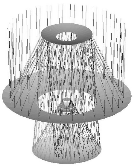
The strength of lies not in a small diffraction limited field of view but in having the widest possible field with the largest aperture. Equipped with a large mosaic of detectors capable of reaching sensitivity limits set only by sky photon noise and atmospheric seeing, such a telescope has unique scientific potential. For the dual requirements of large field and low aberration PSFs, optical systems based on one or two mirrors are inadequate, and three mirror systems with strongly aspheric primary and secondary must be used. Three-mirror telescopes with a parabolic primary, convex spherical secondary and a concave spherical tertiary of equal but opposite curvature, were first explored by Paul [13]. The image is formed midway between secondary and tertiary, with good correction over a wide field. The secondary, located at the center of curvature of the tertiary, has added correction for spherical aberration. For general 3-mirror systems were explored, allowing all three mirrors as well as two inner surfaces of camera windows to have an aspheric figure optimized for wide field. The focal surface was not constrained to be flat, since the dedicated detector mosaics can be configured to approximate a curved field, with each flat device tangent to the focal surface. The optimized design has the tertiary mirror located significantly behind the primary (Figure 1).
The advantages of this arrangement for wide field imaging were recognized by Willstrop[14]. In this recent 5-surface optimization the effects of longitudinal and chromatic aberration are almost eliminated. Detector obscuration is minimized by making the primary and secondary together nearly afocal. The 3 deg field is completely baffled against stray sky light illumination with total obscuration and vignetting held to 26% at the field center and rising to 38% at the field edge. Recently the design has been optimized to deliver high quality images over the entire focal plane [16].
There are many issues to consider in the design of such a facility: what are the trades involved in making the aperture smaller or splitting the effective aperture into multiple telescopes. The optimal strategy hinges on two factors: the optical throughput per telescope/camera and the constraints on the exposure time due to science requirements or the necessity of reaching the sky noise limit.
2.1.1 The power of A
Neglecting exposure time requirements, a general measure of the survey efficiency of a telescope is the figure of merit . Here A is the collecting area, the solid angle of the field of view, the overall efficiency including detector quantum efficiency and d the solid angle of the seeing limited image. In given integration time the size of field larger than that can be explored to given depth is directly proportional to this figure of merit. In the sky noise limit, the surveyed area of sky to a limiting flux per unit time to some S/N is proportional to A:
where is the sky background flux and is the PSF footprint.
Note that this equation is independent of the exposure time. This is because sky noise limited performance was assumed. For the science drivers the exposure time needs to be less than 20 sec. While sky limited operation is not critical for bright objects, the regime of imaging is the faint limit. The square root of the sky background counts in an exposure must greatly exceed the noise of the device. This creates a critical throughput below which the telescope-camera cannot operate efficiently as shown in Figure 2. For a given number of pixels in the FPA, , the flux into each pixel is and the sky noise limit is reached when . In Figure 2, the solid curve represents at A=265 m2 deg2. Two science requirements are shown: short exposures (optical transients and non-trailing for moving objects) s, and sufficient survey pace in deg2 per night in order to cover the entire visible sky in 3 nights (NEO detection). Surveys constrained to short exposures get a double boost from high A: once from area covered to a limiting flux, and once again from shorter times (and thus faster survey pace) required to overcome device noise.
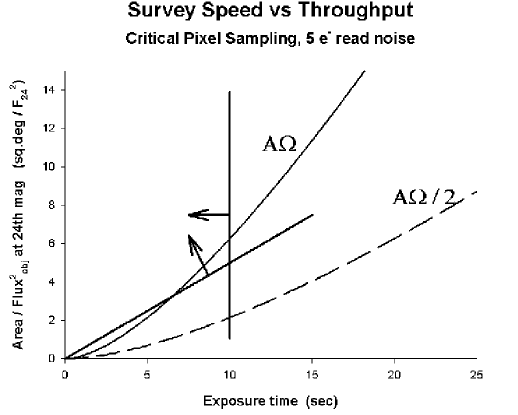
For example, if the detector modules are 2k2k and must be read out in 2 sec, then a read+thermal noise of 5-10 e- is typical of current CMOS or CCD devices cooled to -40 C. In a ten-second exposure we must therefore build up at least 1000 e- of sky in order to have less than a 20% decrease in S/N ratio due to read noise. This leads to a critical A which must be exceeded for each telescope in an array or for a single telescope, in order to go faint fast. The properties of the detector become important for such short exposures. If the exposure is too short, CCD traps are not filled and/or the detector (whether CMOS or CCD) is not sky-noise limited. Low f-ratio illumination is crucial.
2.1.2 Tolerance for maintenance of image quality
The ability to go faint fast is good for control of image systematics. Weak lensing places demands on the image aberrations over the field and their stability. With current telescopes where this is not controlled, on-line convolution of the PSF, fit to all the stars over the field in a given exposure, can correct for PSF ellipticities as bad as 10%, reducing the PSF ellipticity to an average value of about 0.1%. For the low-level cosmic shear work we will need to fit the PSF to many stars over a large field and reduce the PSF ellipticity to 0.01%. However, the mass cluster 3-D tomographic mode, in which typical clusters generate shears of 0.1, will not require such low level shear systematics control. This increased dynamic range for PSF correction will be accommodated by a combination of hardware and software PSF control. We have found that in single exposures reaching 24th mag that there will be enough stars per unit area in the field to make a robust software deconvolution of the spatially varying PSF, if the PSF ellipticity can be kept below 5%.
The is sufficiently fast that this magnitude limit can be reached in only a 10 second exposure. To enable this software AO, the delivered image quality of the must be controlled. Thus, we require hardware control of the telescope optics at that level, along with the corresponding metrology. The Collaboration have undertaken a realistic study of the image aberrations under varying amounts of primary mirror decenter and correcting tilt/decenter of the secondary mirror. The results are quite encouraging [3]. A finite element analysis of the rigid support for the primary suggests that decenters of the primary larger than 100 microns would be unlikely. In order to tie all the optical elements of the telescope together, off-the-shelf laser metrology (20 micron tolerance), along with four stepped out of focus detectors at the field edge, will be sufficient.
Finally, there will be hundreds of exposures of each 7 deg2 part of the sky with the camera rotated at various orientations, thus averaging over remaining systematics and affording the opportunity to cut the sample in various ways. One obvious way is to discard individual exposures with substandard PSF, co-adding images with only the best PSF. Selecting the best 50% seeing, FWHM of 0.5 arcsec or better should be achieved in the co-added stack. How will the residual variations in the telescope optics PSF affect low-level gravitational shear measurements? We have done tests in which we convolve slightly sheared multiple orientations of the HST HDF fields with the telescope PSF at various places in the focal plane and with a 0.5 arcsec atmosphere PSF. We find a negligible effect for the range of telescope PSF variations which go uncorrected: shear error is dominated by the soruce galaxy ellipticity noise rather than telescope systematics.
To maximize the figure of merit for an imaging telescope, it should be in a site with excellent seeing and its focal length must be chosen so the detector pixels will adequately sample seeing limited images. Experience shows that good telescopes at the best sites will deliver images of 0.4 - 0.5 arcsec often. The pixel sampling should be no worse than 0.2 arcsec (the Nyquist sampling criterion) to avoid further significant image degradation, thus each square degree on the sky must be sampled by over 320 million pixels in the detector mosaic.
2.2 Comparison with some existing and proposed imaging telescopes
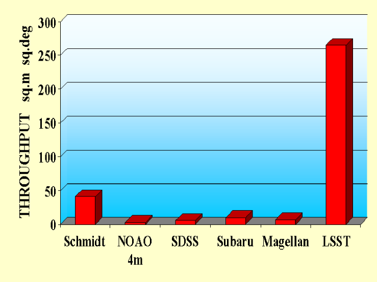
Comparing the 8.4 m telescope with the SDSS, and allowing also for its increased pixel sampling and resolution, the advantage in figure of merit is by a factor of close to 200. The wide field optical cameras to be used with existing new-technology larger telescopes have throughputs which are not substantially larger than the SDSS, in the range 5 - 10 m2 deg2. The science drivers for the put a premium on large . The throughput of various telescopes useful for good image quality wide-field work is compared in Figure 3. This facility will provide a capability that is completely beyond any existing telescope and uncovers a region of parameter space orders of magnitude beyond current limitations. Capable of reaching 24th mag in a single ten second exposure, the will be able to reach 10 limiting magnitudes of , and over a 7 deg2 field in 3 nights of dark time.
3 The Camera
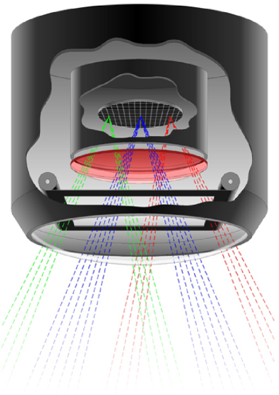
A plate scale of 51m/arcsec ensures that seeing-limited images will be well sampled by the 10 m pixels. The optimized Paul optical design puts the camera in the beam from the secondary: not a lot of room for filter and shutter mechanisms. For a large aperture the resulting detector array is necessarily large, and the usual vacuum dewar would have an unusually large and thick glass window. This window would have to be curved to take the 14-ton load, and mechanisms like a shutter and filter changer which should reside outside the vacuum would be huge and would be in the beam. However, the large throughput results in very short exposure times (sky noise limit is reached within seconds). Thus, the detector need not be cooled below -40 deg C, and the dewar may be filled with a low thermal conductivity gas like Xenon. Figure 4 shows this layout. The dewar window is thin and not as curved, and there is room in the outer can (filled with dry nitrogen also at atmospheric pressure) for the required mechanical assemblies.
Ghosts from multiple reflections of bright stars can be a problem in wide-field telescopes, particularly with multiple refractive element correctors. The is designed to avoid such a corrector, and the dewar window and filter are placed so far from the CCD that, with standard broadband AR coats, they will supply insignificant ghosting from the inevitable 5th mag stars. The dewar window is 1.3 m diameter, but need not take vacuum loading since the dewar will be filled with atmospheric pressure low-conductivity gas. Its convex meniscus shape adds shell stiffness.
In the current design the FPA is 55 cm in diameter. Cooling requirements are not severe for the detector module mosaic. The criterion is that the dark rate be less than the sky photon rate in the darkest filters. With an MPP CCD or current CMOS devices, low dark rates can be achieved at a device temperature of -30 to -40 C. In the worst case of a 10 second exposure in a dark band a read noise of 4 e- rms will be acceptable.
3.1 Mechanical issues
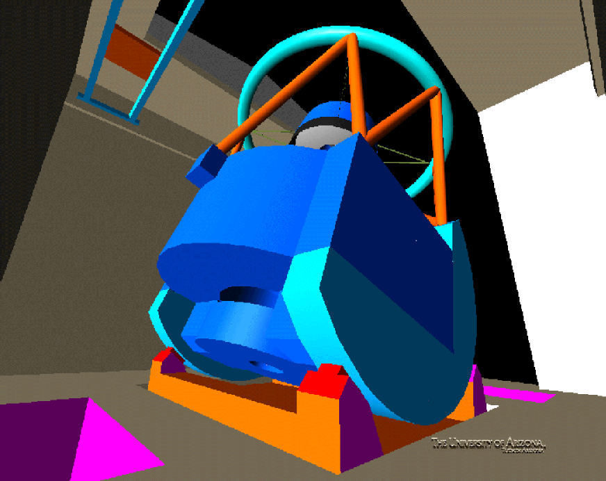
While many of the exposures are shifted on the sky by a fraction of the 3 deg field, it will be necessary to slew the telescope by about three degrees fairly often. With a 2 second read time, it will be important to design a system which can repoint gracefully and fast. Exposures of 10 sec do not require guide stars if the tracking is sufficiently accurate. Slew and settle time for the telescope are dependent on overall structural stiffness. The current design by Davison[5] (Figure 5) is compact and stiff, with a first resonance above 8 Hz. A related issue is the servo system, and an end-to-end systems analysis will be undertaken.
There are two main mechanical challenges with the camera. As seen in Figure 1, the camera is in the beam from the secondary. The axial cross section of the camera assembly is thus constrained, prohibiting conventional outboard filter changing mechanisms and shutter mechanics. Whether a shutter is even necessary depends on the nature of the detector module. CMOS arrays, having several transistors associated with each pixel, are self-shuttering. CCDs have been developed in which a horizontal electric field can pinch off charge collection, but this fails for red wavelengths where photons penetrate 50 microns. So CCD arrays will require some type of shutter. Engineers at LLNL have been studying several compact shutter designs which promise long mean time to failure together with uniform illumination over the focal plane. While one of the desirable properties of the detector module is self-shuttering, either CMOS or CCD solutions to the detector modules are viable.
The filter change mechanism is the other challenge. The science drivers, even for the NEO survey, require several band exposures. Some science can settle for long filter change times, while some projects require that at least a few filters be available within minutes. Compact filter change/storage designs have been studied for the camera. In particular, a solution is now being studied in which four filters are stored in the outer chamber of the dewar [10]. A filter cassette design, with storage behind the primary mirror is also being studied.
4 The Focal Plane Array
The design of the started with the output: the question was “what data are required for the science?” This drives the number of pixels, their response vs wavelength, and their dark and read noise. Covering the 3∘ diameter field of view with 0.2 arcsec pixels (to provide critical sampling in the best seeing) requires 2.3 Gpix.
The size of the pixels is set by a number of considerations: (1) the minimum and maximum acceptable stored charge (dynamic range per pixel), (2) the requirement that we maximize the product, (3) sky noise limited operation with 10 sec exposures, (4) depth of focus (a consideration at near-IR where photons penetrate silicon), (5) maximize the near-IR QE (a pixel geometry constraint), (6) good performance in the near-IR, and (7) minimize device area in order to maximize yield.
These demands jointly constrain the pixel size to about 10 microns. The camera will use state-of-the-art imager and microelectronics technology which was developed over the past few years for a variety of applications ranging from HDTV to fast low-noise multiplexers for IR arrays to fast low noise readout arrays. High QE in the near-IR favors micron thick fully depleted high-resistivity silicon. Recently, spectacular QE curves have been obtained for such devices by several labs. The individual array modules will be small, 1K or perhaps 2K, so that the the circular field and the curvature (if any) of the focal plane can be matched precisely: the depth of focus is 10m. Parallel multiplexing many discrete modules also allows for fast readout, which will be critical for efficiency. The clocking electronics will be integrated with the individual detectors and there are several attractive options for analog and digital ULSI packaging which minimize the interconnections.
There are several factors leading to the need to break up the FPA into small modules. The worst case curved focal plane accommodates devices smaller than 2 cm, without bending. Device yield decreases as the area increases, leading to practical FPA segments of several cm or smaller size. The readout time requirement, given that the exposures are as short as 10 sec, is 2 sec. With a pixel size of 10 microns, low noise (e) reads of CCDs can be performed with correlated double sampling at individual device rates of less than 1 Mpix/sec, leading to a size limit of roughly 2 Mpix or 1.5 cm. CMOS arrays can read faster.
We require an FPA with imager modules with the following properties: 4-side edge buttable[6], overall 90% fill factor or higher, high QE 350-1050 nm, and integrated readout and A/D electronics. The idea is to develop self-contained imager modules which have a DC voltage in, bi-directional communication (possibly FPGAs), and digital data out. For the imager we are examining several CCD technologies as well as CMOS arrays[2]. Another possibility, already under development, is a module consisting of an array of CCDs, with integrated controller. These matters are discussed in a companion paper by Lesser and Tyson [7].
5 Observing Strategy
While each of the science programs use the multiple sky-limited short exposures in different ways, the observing strategy is set mostly by the transient and moving object survey programs. The number of Potentially Hazardous Asteroids (PHAs) rises steeply as their size decreases, and they are extremely faint. No current telescopes are capable of surveying for them. Deep imaging is necessary but not sufficient. In oder to avoid confusion with main belt asteroids one must go faint fast. Preliminary orbits must be reliably linked across nights and weeks. A PHA moving with an angular speed of up to 2.5 deg/day will not trail in 2x10 sec exposures, and thus it will be detected in the same way as the main belt asteroids (whose typical velocity is 0.3 deg/day). For R24 mag) the typical distance between two main belt asteroids is 2 arcmin on the Ecliptic. They can be linked in two 10 sec exposures 15 min apart, in which they will move up to 10 arcsec. With this 15 min based velocity vector they can be linked again within 3 nights with false positive rate of less than 1%. The interesting range for PHAs extends up to 10 deg/day and PHAs with angular speeds greater than 2.5 deg/day will be slightly trailed. The trailing will help to link them in two exposures taken 15 minutes apart, but also increases the detectable size limit.
6 Data Rate and Pipeline
The facility will produce over 7 TB of raw data per night, compressed. Such data rates are commonplace in radio astronomy and particle physics. The huge difference here is that we must keep all this data as well as analyze it in real time! The required hardware for image processing, including frame dewarping, is achievable based on what is currently under development in the lab. Routine image processing on large images is easily parallelized and ideally suited to clusters of inexpensive, commodity computers, especially given the parallel nature of the readout. The HDTV and other industries are driving the development of storage capability which will become available at reasonable cost in just the next few years. Disk access will not be a limiting factor either. The software pipelines will present more of a challenge. Even here, however, previous projects such as the searches optical transients have demonstrated that efficient real-time use can be made of very large data streams. These projects,like SuperMACHO and the Deep Lens Survey, had to develop pipeline software for fast transient detection[17, 4, 20]. Likewise, the SDSS had to develop a photometric pipeline[8]. These surveys are precursors to the , and the lessons learned and many of the algorithms will be put to work on the pipelines.
The photometric pipeline will process the data through flat fielding and will also produce a running catalog of detected and photometered objects. There will be various taps in the pipeline for data quality assessment at various stages of processing. Some aspects of this pipeline will have to be detector specific. Hopefully, we will gain insight into the detector features before the main camera is completed. The architecture of the data flow is still being worked out. It is already known that after the automated photometric pipeline there will be several parallel pipelines producing different data products. One of them will be the Transient pipeline, tuned to detect transient and also moving objects. There will also be a parallel pipeline for Moving Objects which will take inputs from the database, the Transient pipeline, and the camera. All these pipelines will most likely be evolutions of similar ones which are now being refined for current surveys.
The job of these transient pipelines will be aided immensely by having a pre-existing deep multicolor photometric catalog of the area being surveyed. An initial 2 years may be used for just this purpose, building up depth as the main survey proceeds later. One of the lessons we have learned from previous surveys is that the cost of the software effort will be comparable to the telescope hardware or camera. With over 10 TB of new data every night, we have to do it right. Cutting corners on software support is not cost-effective.
More important than how we process the data is what we do with it. The traditional mode of observing must give way to a dedicated program, with the community sharing the data. In addition to weak lensing, the search for near-Earth objects, outer solar system objects, and high-redshift SN will benefit greatly, and a vast amount of parameter space will be opened up in the search for GRB counterparts and previously unknown types of optical transients. These projects can only be done with a telescope that can go deep over a wide field in a short time, combined with sensible data management and analysis.
7 Community access, data analysis and mining
All the will be public, the transient and moving objects immediately and co-added imaging and photometric catalogs as soon as calibrated and quality assessed. Data products will consist of photometric catalogs which will be continuously updating during the survey, optical burst announcements and characteristics, a moving object database, deep co-added images in at least 5 bands (updated on a regular schedule), and the huge time-tagged processed image database which will climb to around 15 Petabytes after ten years.
Alerts and some catalogs could easily be on-line. The full photometric catalog will probably be too big for easy remote access. This of course is also true of the Petabyte imaging database. These various data form a pyramid. Most of the users will start from the top, and there must be tools for searching remotely. But large users must be accommodated in a different way. Most of the science to emerge from the and its database will be statistical in nature and will thus involve correlations over large parts of the data. In fact it is often the unexpected correlation that is the most interesting scientifically. Two things must happen to enable this key mode of data analysis: efficient algorithms for statistical analysis must be developed, and this computation must be via high bandwidth to the spinning disk database storage facilities. Data backup via multiple nodes would thus serve two purposes. Clusters of computers co-located with the disk farms would assure both community access and high local I/O bandwidth.
Crafting the software pipelines and developing efficient database management tools and the algorithms for data mining will be more challenging than the pre-processing computation. Most algorithms scale as a power of the number of objects. This traditional approach will be impossible here. Approximate statistical techniques, where the approximation is within the sample variance, and with non-polynomial scaling, will be key [12, 9, 11]. Quality assessment in all phases of the data chain will be important, including the tests of the photometric catalogs and the imaging database. Low level systematic errors must be found and quantified. This process, and the direct involvement of university scientists, could be motivated by funding a key science result.
References
- [1] Angel, J. R. P., Lesser, M., Sarlot, R., & Dunham, T. “Design for an 8 m Telescope to Image a 3 Degree Field at f/1.25 - the Dark Matter Telescope” in Imaging the Universe in Three Dimensions: Astrophysics with Advanced Imaging Devices, eds. W. van Breugel, J. Bland-Hawthorne, ASP Conference Series 195, (Astron. Soc. Pacific, San Francisco) 81 (2000).
- [2] Y. Bai, J. T. Montroy, J. D. Blackwell, M. C. Farris, L. J. Kozlowski, and K. Vural, “Development of hybrid CMOS visible focal plane arrays at Rockwell”, Proc. SPIE Vol. 4028, p. 174-182 (2000).
- [3] C. F. Claver and J. H. Burge, “Active Alignment of the 3-Mirror LSST,” Proc. SPIE 4836-25 (2002).
- [4] K. Cook, “Exploring the Time Domain with LSST: Lessons learned from MACHO” Proc. SPIE 4836-52 (2002).
- [5] W. Davison, “Large Synoptic Survey Telescope mechanical structure and design” Proc. SPIE 4836-18 (2002).
- [6] M. P. Lesser and D. Ouellette, “Fully Buttable Imagers,” Scientific Detectors Workshop 2002, P. Amico and J. Beletic, eds., (2002) in press.
- [7] M. P. Lesser and J. A. Tyson, “Focal Plane Technologies for LSST” Proc. SPIE 4836-38 (2002).
- [8] R. Lupton and Z. Ivezick, “SDSS Imaging Pipelines” Proc. SPIE 4836-49 (2002).
- [9] A. Moore, etal. “Fast Algorithms and Efficient Statistics: N-Point Correlation Functions” in Mining the Sky Proc. MPA/ESO/MPE Workshop. eds. A.J. Banday, S. Zaroubi, and M Bartelmann (Springer-Verlag, 2001) p. 71; astro-ph/0012333 (2001).
- [10] B. M. Starr, etal. “LSST Instrument Concept,” Proc. SPIE 4836-37 (2002).
- [11] A. Szalay, “Petabyte-scale Data Mining: Dream or Reality?” Proc. SPIE 4836-47 (2002).
- [12] I. Szapudi, et al. “Fast CMB Analyses via Correlation Functions” astro-ph/0010256 (2000).
- [13] M. Paul, “Systèm Correcteurs pour Réflecteurs Astronomiques,” Rev. d’Optique, 14, 169-202 (1935).
- [14] R. V. Willstrop, 1984 ”The Mersenne-Schmidt – A three-mirror telescope” MNRAS, 210, 597
- [15] website: http://lsst.org
- [16] L. G. Seppala, “Improved Optical Design for the Large Synoptic Survey Telescope,” Proc. SPIE 4836-19 (2002).
- [17] C. Smith, “SuperMACHO and Supernova Projects at NOAO/CTIO” Proc. SPIE 4836-55 (2002).
- [18] G. E. Sommargren and J. H. Burge, “Testing the Large Synoptic Survey Telescope (LSST) Aspheric Convex Secondary” Proc. SPIE 4836-20 (2002).
- [19] J. A. Tyson, & R. Angel, “The Large-aperture Synoptic Survey Telescope” The New Era of Wide Field Astronomy, ASP Conference Series, R. Clowes, ed., 232, 347 (2001).
- [20] D. Wittman, “Deep Lens Survey” Proc. SPIE 4836-12 (2002).