Further author information: (Send correspondence to P.B.)
P.B.: E-mail: Pascal.Borde@obspm.fr
Copyright 2002 Society of Photo-Optical Instrumentation Engineers.
This paper will be published in the proceedings of the conference
Interferometry for Optical Astronomy II, part of SPIE’s Astronomical
Telescopes & Instrumentation, 22–28 August 2002, Waikoloa, HI and is made
available as an electronic preprint with permission of SPIE. One print or
electronic copy may be made for personal use only. Systematic or multiple
reproduction, distribution to multiple locations via electronic or other means,
duplication of any material in this paper for a fee or for commercial purposes,
or modification of the content of the paper are prohibited.
10-m wavefront spatial filtering:
first results with chalcogenide fibers
Abstract
Wavefront cleaning by single-mode fibers has proved to be efficient in optical-infrared interferometry to improve calibration quality. For instance, the FLUOR instrument has demonstrated the capability of fluoride glass single-mode fibers in this respect in the K and L bands. New interferometric instruments developped for the mid-infrared require the same capability for the 8–12 m range. We have initiated a program to develop single-mode fibers in the prospect of the VLTI mid-infrared instrument MIDI and of the ESA/DARWIN and NASA/TPF missions that require excellent wavefront quality. In order to characterize the performances of chalcogenide fibers we are developping, we have set up an experiment to measure the far-field pattern radiated at 10 m. In this paper, we report the first and promising results obtained with this new component.
keywords:
Spatial filtering, interferometry, single-mode fibers, mid-infrared1 INTRODUCTION
Whatever the cause of corrugations on interfering wavefronts, defects on the mirrors or effect of the turbulent atmosphere, they result in a loss in the coherence factor measured by an interferometer. Spatial filtering by a pinhole overcomes this problem by removing the high spatial frequencies from the wavefronts. However, the pinhole has to be designed for a specific wavelength and does not provide a good correction of low spatial frequency defects. An alternative consists in modal filtering by a single-mode waveguide: the shape of the wavefronts that have been guided into this device only depends on the characteristics of the guide (choice of materials and geometry); this way, two beams can be recombined with a full interferometric efficiency. This property holds for wavelengths above the cutoff wavelength of the guide, as the only mode to propagate is then the fundamental one.
Since 1995, the FLUOR[1] instrument has demonstrated the use of fluoride single-mode fibers to measure high precision coherence factors on many stars in the near infrared (K and L bands). It is now followed by the VLTI near-infrared instruments VINCI[2] (K band) and AMBER[3] (H and K bands). Unfortunately, no single-mode fiber is available nowadays for the mid-infrared. This is an issue for the VLTI 10-m instrument MIDI[4] (N band) and for its ambitious followers on the ground like GENIE[5], or in space like DARWIN[6] that aims at performing the spectroscopy of exoplanets in the 8–20 m range. In this prospect, we have undertaken an activity of research and development on single-mode fibers for the mid-infrared, with the partnership of Le Verre Fluoré, a leading French company in this sector. In this paper, we report the promising results obtained with chalcogenide fibers in terms of transmission, wavelength range and modal filtering.
In Sect. 2, we review the fundamental properties of single-mode fibers and detail the characteristics of the prototype manufactured by Le Verre Fluoré. Section 3 first describes the experiment that has been set up to test the filtering capability of the fibers, and then discusses the results of our measurements.
2 PROTOTYPE MANUFACTURING
2.1 Single-mode fibers
An optical fiber becomes single-mode when it is used at a wavelength longer than the cutoff wavelength
| (1) |
where is the core radius, NA is the numerical aperture, and are respectively the core and the cladding refractive indices[7]. In this situation, the only guided mode is the fundamental one, denoted LP01, whose shape is almost Gaussian. All the energy injected into the fiber will either excite this mode or propagate into the cladding. If the fiber is long enough, the cladding modes are completely attenuated and do not come out.
2.2 Selected materials
For this applied research, Le Verre Fluoré was funded by the French military administration, la Direction Générale de l’Armement (DGA), and associated to three research laboratories for the full characterization of the produced fibers: the Laboratoire de Physique des Lasers (LPL), the Institut d’Astrophysique Spatiale (IAS), and the Département de Recherches Spatiales (now LESIA). The goal assigned by the one-year contract (dec. 1999–dec. 2000) was to manufacture a single-mode waveguide for the 8–12 m range with losses less than 3 dB/cm.
Two solutions were selected by Le Verre Fluoré to achieve this goal, as transparent materials in the mid-infrared suitable for fiber manufacturing are either
-
(a) silver halides, e.g. AgCl or AgBr, or
-
(b) chalcogenides, e.g. AsxSeyTez.
In order to obtain a specific refractive index, different halides are mixed together in case (a), whereas the proportions x, y and z are varied in case (b). Silver halides have the appealing property of being transparent up to 30 m with transmission losses that can be as low as 10-3 dB/km. However, they are polycristals and as such are turned into fibers by extrusion (the material is pushed through a hole), a process difficult to master. On the other hand, chalcogenides are glasses, so fibers can be manufactured by drawing, but they become opaque beyond 16 m. In the prospect of the short-term DGA contract, the second solution appeared easier and was prefered. Nevertheless, silver halides are certainly the material that will be needed in the future for ground-based applications in the Q band (17–25 m), or for DARWIN in space at the longest wavelengths of the spectrum.
2.3 First prototype characteristics
The characteristics of the first fiber prototype are listed in Table 1.
| Material | As2Se3/GeSeTe1.4 |
|---|---|
| Core diameter | 40 m |
| Cladding diameter | 210 m |
| Numerical aperture | 0.15 |
| Cutoff wavelength | 8.1 m |
| Length | 8 cm |
| Transmission losses | dB/cm |
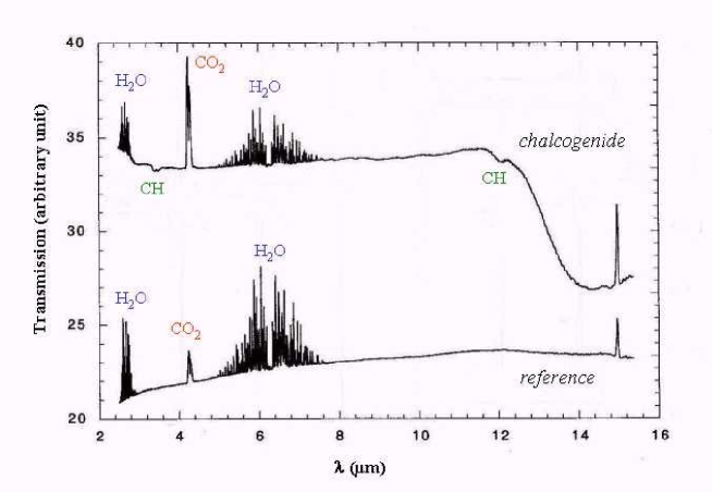
The transmission losses were determined by Le Verre Fluoré using the cut-back method: the throughput of a sample is measured twice, before and after shortening one end; the difference in throughput leads to the transmission losses given the length of the missing piece. The losses amount to at 10 m for our 8-cm prototype. Besides, the cutoff wavelength leaves a signature in the spectral loss curve: the transition between two to one guided mode results in a downward slope. The cutoff wavelength was thus estimated to 8.1 m. A high-resolution transmission spectrum of the material itself was also recorded with the FTS microscope of the LURE laboratory in Orsay (Fig. 1). This spectrum shows a flat transmission until 12 m and no impurity except for a very little quantity of CH that will be eliminated when the next fiber is drawn.
 |
Although these first results seem encouraging, the ultimate test remains to inject a corrugated wavefront in the fiber and to check the field profile at the end. In the next section, we describe this experiment and its results.
3 FAR-FIELD MEASUREMENTS
3.1 LPL testbed
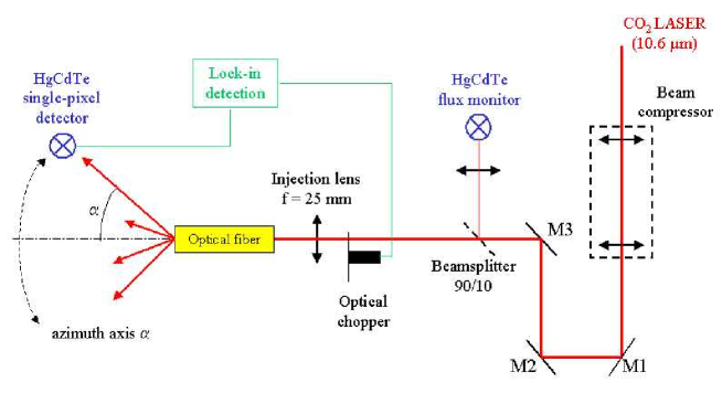
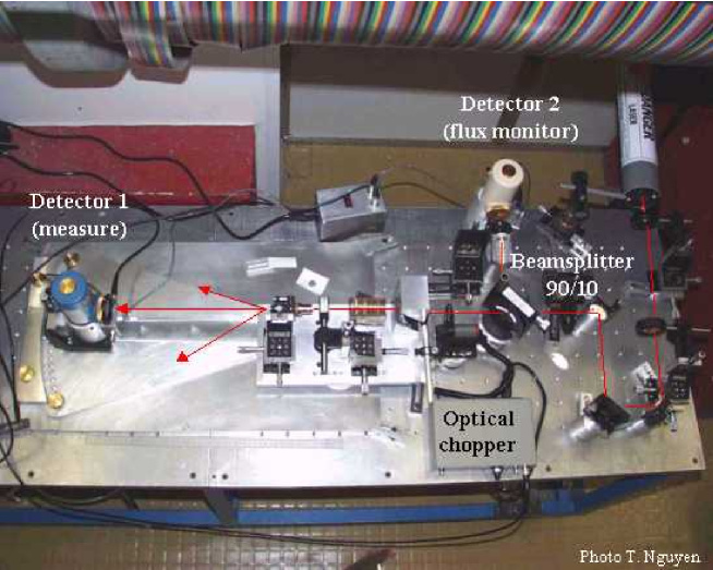
Single-mode fiber theory[7] establishes that the fiber end radiates a free diverging wave beam, the fundamental fiber mode becoming a fundamental Gaussian mode with a good approximation. The waist of the radiated Gaussian beam is located on the fiber end and has a radius equal to the radius of the fiber core. We have set up an experiment (Figs. 2–3) to check the quality of the modal filtering by measuring the far-field radiation pattern of the fiber (experiments of this kind have already been reported in the literature[8]).
 |
 |
The testbed is hosted by the Laboratoire de Physique des Lasers, a laboratory that operates several highly stabilized CO2 lasers designed for metrology applications. A fraction of a 10.6-m laser beam, primarily dedicated to another experiment, is folded in the direction of our optical table. The beam is first recollimated by an afocal telescope. Part of the light is then sent to a flux monitor (HgCdTe monopixel detector), whereas the main beam is adjusted in height by a periscope before being focused onto the fiber core by an injection lens. The light propagates along the 8-cm fiber and is radiated freely in space. If all the modes but the fundamental have been filtered out, the energy is expected to be radiated within in a cone of about , since the waist radius is m.
The far-field pattern is recorded by moving a single-pixel HgCdTe detector in the portion of space in front of the fiber. Because of the high background emissivity at 10.6 m, a lock-in detection system is mandatory. The detector can be positioned at three different distances from the fiber end: 10, 20 or 30 cm and is adjustable in height. The exploration of the 3D far-field pattern ( in azimuth, in height) is done manually, and is completed in about one hour and a half for a resolution of .
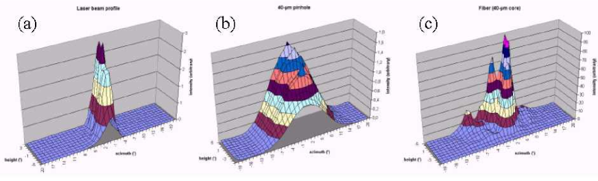
We have first measured the laser beam profile by replacing the fiber by a convergent lens to produce a divergent beam in a cone opened enough to be sampled by our system: this profile (Fig. 4a) is not Gaussian as the laser is not single-mode. In a second step, the experimental procedure is validated by recording the far-field radiation pattern of a 40-m pinhole: the profile (Fig. 4b) has the expected Gaussian shape and width.
 |
3.2 First far-field profiles
At our great disappointment, the intensity profile radiated by the fiber was not found to be Gaussian at all (Fig. 4c). Three modes can be seen in the portion of space that was explored. Only the radius of the whole bunch of modes is compatible with a diffraction by the fiber core, whereas their individual radii correspond more closely to a diffraction by the cladding. This indicates that the cladding modes are not filtered out. A first explanation could be that the fiber sample is simply not long enough to eliminate the unguided light. However, a previous experiment with a 1-mm long fluoride glass fiber designed for 2 m and used at 10 m have shown better results[9]. The correct explanation was found by taking into account the protective layer surrounding the cladding. This extra layer happens to have a refractive index inferior to that of the cladding itself. This results in a second guiding structure, concentric to the core-cladding pair, that causes the persistent cladding modes. As a consequence, the transmission figure of Table 1 is probably overestimated as it includes unwanted energy. The problem could be solved if another material were chosen for the protective layer, but at this date, the DGA contract came to an end. Nevertheless, some research could be pursued on a collaborative basis with Le Verre Fluoré.
3.3 Second generation samples
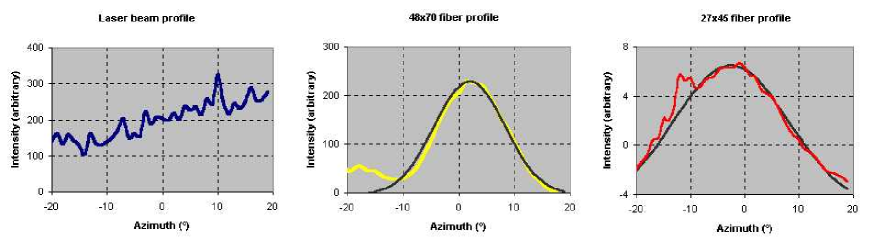
Because of the lack of fundings and despite the lessons learnt from the first campaign of measurements, the fibers produced in the frame of the DGA contract had to be re-used. A second generation of fibers were obtained by removing the extra layer and part of the cladding of the first generation by chemical stripping. Thus, the cladding is studded with diffusive centers favoring the elimination of cladding modes. Besides, the fibers were coated with a new protective enveloppe in lead, a 10 m absorbent. The two new components are shorter, 4-mm long, with thinner claddings: the core/cladding dimensions are 48 m/70 m and 27 m/45 m respectively. Figures 5 display the 1D far-field radiation patterns of the laser beam and of both fibers that were recorded during a second measurement campaign. A best-fit Gaussian curve has been superimposed for comparison. Although there is still a small second lobe in one case (48 m/70 m), the profiles appear to be much closer to what we are seeking. However, their width is not completely consistent with the prediction of the standard diffraction theory. We think the cladding is so thin that it can no longer be considered as infinite as it is usually assumed in the standard fiber theory. The cladding will be thicker when the industrial process is ready. A close examination of the fibers with a binocular microscope has revealed geometrical defects and a small asymmetry of the fiber cores that are lilkely to be responsible for the high frequency defects and the small second lobe. This has been recently improved by Le Verre Fluoré, still using the fibers originally drawn, and we plan to put under test these new components this fall.
 |
4 CONCLUSION
We have presented the characteristics of chalocogenide fibers we are developping to perform modal filtering in the mid-infrared. We have reported promising first results with these components. Because of our present lack of funding, we still work on the fibers that were drawn in the first place. As they could recently be improved nonetheless, and are now ready for testing, we will start a new measurement campaign next fall. If these fibers are successfully tested, they could be integrated in MIDI next year. The following step would be then to develop silver halide fibers for modal filtering up to 20 m, i.e. through the full wavelength range of DARWIN.
References
- [1] V. Coudé du Foresto, G. Perrin, C. Ruilier, B. Mennesson, W. Traub, and M. Lacasse, “FLUOR fibered instrument at the IOTA interferometer,” in Astronomical Interferometry, R. D. Reasenberg, ed., Proc. SPIE 3350, pp. 856–863, 1998.
- [2] P. Kervella, V. Coudé du Foresto, A. Glindemann, and R. Hofmann, “VINCI: the VLT Interferometer commissioning instrument,” in Interferometry in Optical Astronomy, P. Léna, A. Quirrenbach, eds., Proc. SPIE 4006, pp. 31–42, 2000.
- [3] R. Petrov, F. Malbet, A. Richichi, K. Hofmann, D. Mourard, K. Agabi, P. Antonelli, E. Aristidi, C. Baffa, U. Beckmann, P. Berio, Y. Bresson, and F. Cassaing, “AMBER: the near-infrared focal instrument for the Very Large Telescope Interferometer”, in Interferometry in Optical Astronomy, P. Léna, A. Quirrenbach, eds., Proc. SPIE 4006, pp. 68–79, 2000.
- [4] C. Leinert, U. Graser, L. Waters, G. Perrin, B. Lopez, V. Coudé du Foresto, A. Glazenborg-Kluttig, J. de Haas, T. Herbst, W. Jaffe, P. Lena, R. Lenzen, R. le Poole, S. Ligori, R. Mundt, J.-W. Pel, I. Porro, and O. von der Luehe, “10-m interferometry on the VLTI with the MIDI instrument: a preview,” in Interferometry in Optical Astronomy, P. Léna, A. Quirrenbach, eds., Proc. SPIE 4006, pp. 31–42, 2000.
- [5] P. Gondoin, A. Glindemann, C. Fridlung, B. Koehler, N. Rando, R. Wilhelm, O. Absil, C. Erd, R. H. den Hartog, L. Labadie, I. Mann, A. Richichi, Z. Sodnik, A. J. Peacock, M. Tarenghi, S. Volonte, and A. Karlsson, “Darwin ground-based European nulling interferometer experiment (GENIE),” in Interferometry in Optical Astronomy II, W. A. Traub, ed., Proc. SPIE 4838, 2002.
- [6] A. Léger, J.-M. Mariotti, B. Mennesson, M. Ollivier, J.-L. Puget, D. Rouan, and J. Schneider, “Could We Search for Primitive Life on Extrasolar Planets in the Near Future?,” Icarus 123, Issue 2, pp. 249–255, 1996.
- [7] E.-G. Neumann, Single-mode fibers, Fundamentals, Springer-Verlag, Berlin, 1988.
- [8] K. Hotate and T. Okoshi, “Measurement of refractive-index profile and transmission characteristics of a single-mode optical fiber from its exit-radiation pattern,” Applied Optics 18, No. 19, pp. 3265–3271, 1979.
- [9] G. Perrin, M. Ollivier, and V. Coudé du Foresto, “Spatial filtering with single-mode fibers for 10 m interferometry,” in Interferometry in Optical Astronomy, P. Léna, A. Quirrenbach, eds., Proc. SPIE 4006, pp. 31–42, 2000.