Physical conditions in the Protoplanetary Nebula CRL 618 derived from observations of vibrationally excited HC3N
Abstract
We used the Effelsberg 100 m and IRAM 30 m telescopes to observe vibrationally excited cyanoacetylene () in several rotational transitions toward the proto-planetary nebula CRL 618. Lines from 9 different vibrationally excited states with energies ranging up to 1600 K above ground were detected. The lines show P Cygni profiles indicating that the emission originates from an expanding and accelerating molecular envelope. The rotational temperature varies with velocity, peaks at 520 K, 3 blue-shifted from the systemic velocity and decreases with higher blueshift of the gas. The column density of the absorbing is 3–6 . We modeled spectra based on spherical models of the expanding envelope which provide an excellent fit to the observations, and discuss the implications of the models. Additionally, lines from 13C substituted cyanoacetylene were observed. They can be used to constrain the 12C/13C ratio in this source to .
1 Introduction
At the end of their lives, stars go through a sequence of red giant phases accompanied by intense stellar mass loss. This results in atomic and molecular circumstellar envelopes enshrouding the central asymptotic giant branch (AGB) stars and leading to bright infrared sources. Eventually the star evolves into a white dwarf hot enough to ionize the envelope, starting the formation of a planetary nebula (PN). The transition phase between the AGB and PN stages is very short; consequently objects evolving through it, so-called proto-planetary nebulae (PPNe), are very rare. Their physical and chemical properties define the starting conditions for planetary nebula evolution. Therefore, it is of importance to determine these characteristics observationally. Reviews on this subject are given in Kwok (1993) and Hrivnak (1997).
CRL 618 is the archetypical PPN. Its circumstellar, expanding envelope emits in a multitude of molecular lines (e. g. Bujarrabal et al. 1988) and contains molecules as complex as benzene, which was recently discovered with the Infrared Space Observatory by Cernicharo et al. (2001); it shows a bipolar morphology/outflow in the optical, CO, and HCN emission (Meixner et al. 1998; Neri et al. 1992); the bipolar outflow lobes were imaged at high angular resolution with the Hubble Space Telescope (Trammell 2000); a compact, possibly variable Hii region is just emerging around the central star (Kwok & Bignell 1984; Martin-Pintado et al. 1993).
To study the physical and chemical properties of the circumstellar envelope of CRL 618, we started a project to observe the carbon chain molecules HCN, , and in their vibrationally ground and excited states. Carbon chain molecules were chosen since they might be related to the formation of carbon dust grains. Another objective was that they provide many rotational lines of different vibrational excitation in a relatively small spectral range, allowing observations of various lines with equal spatial resolution. The vibrationally excited levels are populated by IR radiation, and thus provide the interesting information about the IR fields and excitation of the gas (Wyrowski et al. 1999) which would not be accessible in the infrared itself due to the high dust extinction.
In this paper, we present an observational study of vibrationally excited in CRL 618 carried out using the Effelsberg 100 m and the IRAM 30 m telescopes. In the next section we briefly describe the observing techniques. In Sect. 3, we summarize our main results and in Sect. 4 the data will be interpreted in terms of an expanding, molecular circumstellar envelope. A discussion of the analysis comparing our new results with complementary molecular studies from the literature is then given in Sect. 5.
2 Observations
2.1 Effelsberg 100m
We observed CRL 618 with the Effelsberg 100m telescope of the Max-Planck-Institut für Radioastronomie on 1998 April 23. The front end was the facility 7 mm HEMT receiver tuned to the frequency of the , transition at 45490.313 MHz. Our spectrometer was a 8192 channel autocorrelator which we used with 8 overlapping subunits of 80 MHz bandwidth to cover a total of 520 MHz. The resulting spectral resolution was 0.3 MHz after smoothing the data to increase the signal-to-noise ratio. The beam at the frequencies of the lines was 20″. Pointing was checked at roughly hourly intervals by means of continuum scans on CRL 618 itself. We found the pointing to be accurate to within 4″. Our absolute calibration was based upon continuum scans through W3(OH), 3C84, and 3C273, assuming flux densities of 3.5, 6, and 25 Jy, respectively, and should be accurate to 25 %.
2.2 IRAM 30m
The observations with the IRAM 30m telescope were conducted on 1998 July 17 and 18. Using the facility SIS receivers simultaneously at 109.3, 136.6, and 209.4 GHz with half power beam widths of 22″, 17.6″, and 11.5″, and system temperatures of 200, 350, and 500 K, respectively. Our spectrometers were an autocorrelator with 1633 channels and 0.31 MHz resolution and two filter-banks with 1 MHz resolution and 512 channels. All lines were observed in the lower sideband with typical sideband rejections of 0.003, 0.025, and 0.04, at 109.3, 136.6, and 209.4 GHz, respectively. The wobbling secondary mirror was used with a beam throw of 200″ and a frequency of 0.25 MHz, resulting in spectra with flat baselines. The antenna main beam efficiencies, measured on Mars, were 0.63, 0.51 and 0.45, at 109.3, 136.6, and 209.4 GHz, respectively. We estimate that our absolute calibration uncertainy is lower than 25 %.
3 Results
3.1 The 100m observations near 45 GHz
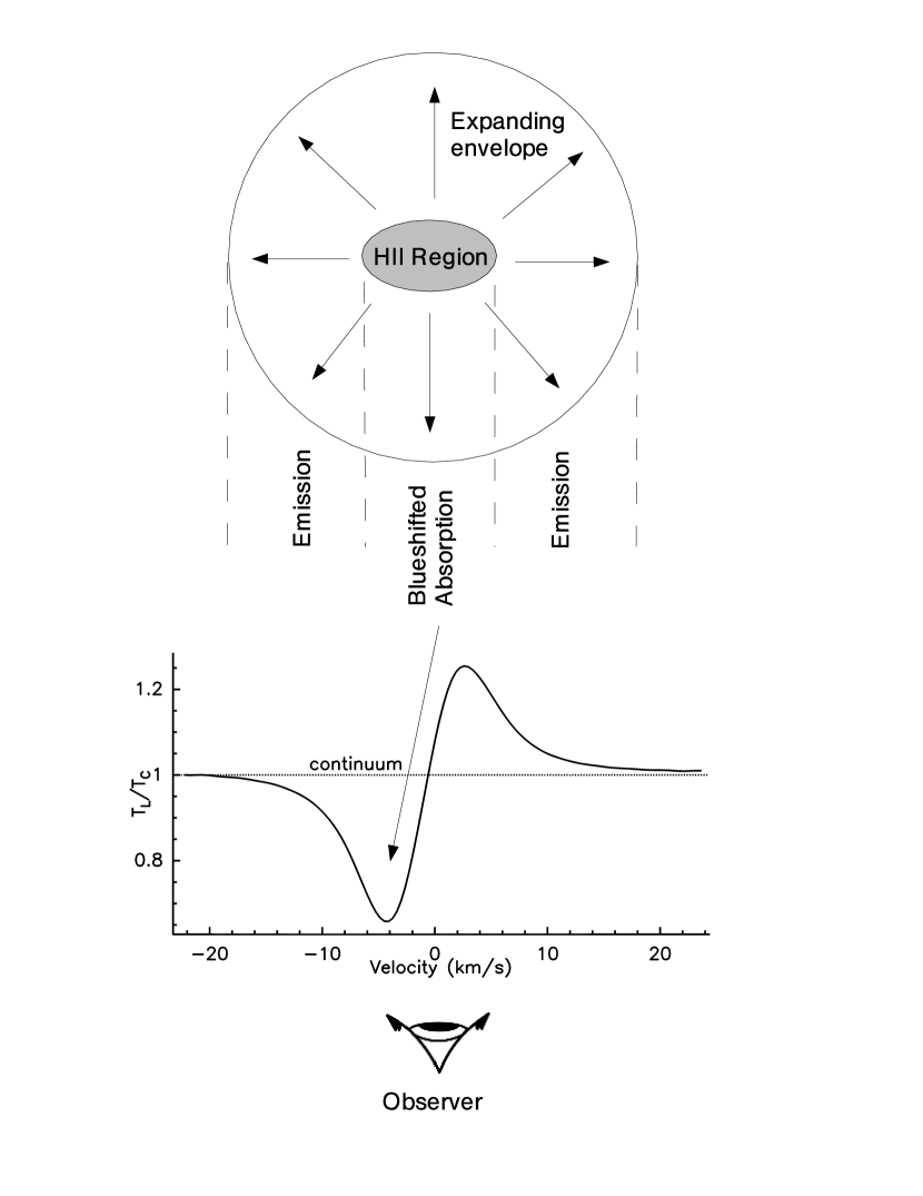
The integrated, baseline subtracted spectrum of CRL 618, merging the different correlator subunits into one spectrum, is shown in the upper panel of Fig. 1. The vibrational ground state line of cyanoacetylene shows a P Cygni profile indicating that the line originates from a hot, expanding circumstellar envelope close to the exciting star. This situation is illustrated in Fig. 2. In all the vibrationally excited lines the emission part is too weak to be detected and only absorption is seen. We have detected pure rotational transitions within all fundamental bending modes , , , the combination mode and the and overtones. The line parameters from Gaussian fits to the lines are given in Table 1. The emission and absorption features of lines showing P Cygni profiles were fitted separately. The brightness of emission lines is given in main beam brightness temperature . We report the strength of absorption features in , with as the continuum temperature, which is proportional to the optical depth of the lines for much smaller than unity. Another advantage of the scale is its independence on the telescope beam size, since the size of the continuum source is considerably smaller then the beam (0.1 0.4 arcsec, Martin-Pintado et al. 1993), as for the millimeter observations described in the next section.
3.2 The IRAM 30m observations
The lower three panels of Fig. 1 show the spectra of , , and . At the frequencies of and , even more lines lines show P Cygni profiles. Comparison of, for example, all the lines demonstrates the continuous transition from absorption to emission of the lines at higher frequencies. Vibrational satellites corresponding to six different modes of vibration of can be identified: Besides the ground vibrational state, all fundamental bending modes , , are detected as in the case of . Additionally the stretching vibration and the combination mode were detected. At 1.3mm (), also the overtone is detected. The latter three vibrational modes correspond to energies from 1300 to 1600 K above ground (see vibrational energy levels in Wyrowski et al. 1999). All the line parameters are given in Tables 2, 3 and 4. Only heavily blended lines were omitted. Several rotational lines of 13C isotopomers of in their bending modes and are observed as well. For all the identifications and analyses we used the improved laboratory frequencies of Thorwirth et al. (2000, 2001). Moreover, the 109 GHz spectrum shows the ground state line of along with its vibrational satellite. A study of this molecule in CRL 618 is discussed in Thorwirth (2001).
3.3 The continuum emission of CRL 618
With the MPIfR 100m telescope, we observed drift scans centered on CRL 618 to obtain its continuum flux density. With the 30m, we estimated millimeter-wavelength continuum flux densities of CRL 618 from the total power offsets of the measured spectra, leading to consistent results between different scans. This method is reliable since we used the chopping secondary mirror so that instrumental and atmospheric drifts are kept small. The measured fluxes densities at all observed frequencies are given in Table 5. In addition, we use the flux densities obtained during our studies of and HCN in CRL 618 (Thorwirth 2001, Thorwirth et al. 2002). In Fig. 3 we compare the measured fluxes with continuum fluxes from the literature. At millimeter wavelengths flux density estimates at similar frequencies agree with eachother within a factor of two, but for longer wavelengths the spread is larger. The observations below 50 GHz were done using the VLA, the 100m and the Arecibo telescope. There is no trend for interferometrically determined flux densities being smaller, so that we don’t think the interferometer observations miss flux due to the lack of short spacings. There is also no clear trend for long term variability: the flux measurements by Turner & Terzian (1984) at 2.4 GHz and by Knapp et al. (1995) at 8.4 GHz were performed in 1981 and 1991, respectively, and are in accordance with the recent VLA 5 GHz value by Thorwirth et al. (2002). On the other hand, variability on shorter timescales might be the case: Kwok & Feldman (1981) reported a brightening of CRL 618 by a factor of 2 over a 2-3 yr interval at frequencies around 10 GHz. For the following 5 years then, no significant increase could be detected (Martin-Pintado et al. 1988). Here we only model the continuum emission for the frequency range of 45–210 GHz covered in the present study, assuming constant flux densities in the short time interval from April to July 1998. The fit to the continuum flux densities in Fig. 3 was obtained by calculating the emerging flux from a homogeneous, circular Hii region. The radius was fixed to 0.11″ (or 190 AU at a distance of 1.7 kpc, Westbrook et al. 1975) to agree with the area of the Hii region obtained by Martin-Pintado et al. (1995). Then the electron temperature and emission measure were chosen to fit the data. Our estimate for agrees with the result by Martin-Pintado et al. (1988). from our fit is 50% higher.
4 Analysis
4.1 Velocities
In Fig. 1, the frequencies of all lines are marked assuming a velocity of the gas of –20.5 . For the emission lines this is a good assumption but it can be seen easily that all the absorption features are blue-shifted. This situation is shown in more detail in Fig. 4 for all unblended lines with either mostly emission or absorption: for the emission lines, there is little variation of velocity with upper energies of the transitions and their average velocity is . For the absorption lines the situation is more complicated. Line velocities below 1000 K show a rising blueshift with decreasing energies above ground. Above 1000 K, the velocities of the absorption is almost constant with a velocity of . In the framework of an expanding cooling envelope this can be interpreted as lower energy lines absorbing mainly from cooler parts of the envelope and higher energy lines from hotter parts closer to the exciting star. A constant velocity for lines higher than 1000 K means, that no is found closer to the star, hence marking the radius of the envelope where the temperature gets small enough that is more effectively produced than destroyed.
For comparison, line velocities taken from Martin-Pintado & Bachiller (1992) are shown in Fig. 4 as well. A rising blueshift with decreasing energies can also be seen in but shifted to lower energies above ground. Addtionally, Martin-Pintado et al. (1992) found another absorption component at about 56 , which was later interpreted (Martin-Pintado et al. 1993, 1995) as being due to postshocked gas from the interaction of the high velocity outflow with the expanding AGB envelope. In this picture ammonia absorption is found symmetrically at 15 from the terminal velocity of the unshocked AGB envelope at –40 . This situation is illustrated in Fig. 5 of Martin-Pintado et al. (1995). In contrast, the absorption profiles are single peaked, suggesting that mainly resides in the unshocked gas. It follows then that the ammonia HC component (Martin-Pintado et al. 1992) shown in Fig. 4 is a blending of the redshifted lobe of the postshock material with the hot unshocked inner part of the AGB envelope, seen in .
4.2 The high-velocity outflow
The lines of the ground vibrational state of show broad lines wings. Hence some is found in the 200 molecular outflow (Cernicharo et al. 1989; Neri et al. 1992). We fitted the line wings by masking all blending lines and the fit results are given in Tables 1–4. The lines with higher excitation do not show any detectable wings, maybe with the exception of the line. Assuming optically thin emission from the line wings, the rotational temperature of the high velocity gas is K, where we included the results of Cernicharo et al. (1989) into the fit. The corresponding column density averaged over a 22″ beam is .
4.3 Temperatures
A rough estimate of the cyanoacetylene level populations can be obtained by using the lines with dominant emission features and plotting the column densities in the levels against energy above ground in a Boltzmann diagram assuming optically thin emission. This leads to a temperature of K which should be considered as the average over all distances from the central star. Since the optical depth of the emission lines is not known a priori, this temperature is only an upper limit.
From Fig. 4, it is clear that absorption lines with velocities of –28 to –27 trace the hottest component of the gas on the line of sight in front of the continuum emission. Using only these vibrationally excited lines, we estimate a temperature of K from a Boltzmann plot. Since the measured quantity is approximately (for ), the optical depth is known and cannot simulate a higher temperature. Fig. 3 shows as a function of frequency and it can be seen that for all frequencies considered in this study K. The reason for the decrease in absoption with increasing frequency is that the emission gets stronger and fills up the absorption part of the line profile.
In a refinement of this method, we divided all the absorption lines into velocity bins of 2 and estimated the temperature in each bin from Boltzmann plots separately. The result is shown in Fig. 5 for (5–4) and (12–11), using a systemic (stellar) velocity of –24.2 (see discussion in the next section). A clear increase of the temperature with lower velocities, presumably closer to the central star, is evident from the population of the vibrationally excited states in both rotational levels, confirming again the interpretation that the lines originate from an expanding cooling envelope.
4.4 A spherical LTE model for the envelope
To account for the observed P Cygni profiles, a more detailed approach is necessary. We therefore modeled an expanding spherical envelope with radial power laws for temperature, density, and velocity:
| (1) |
For the Hii region in the center we used the parameters derived from our continuum observations in Sect. 3.3. We then calculated for a given molecular line and velocity the resulting intensity distribution assuming LTE conditions (see Appendix B), and from that the emerging spectra in our observing beams. Additional free parameters are the systemic (stellar) velocity of the envelope, the intrinsic line width , and the ratio. For the inner radius we used the radius of the Hii region.
Our search for the best fit parameters was guided by results of the previous subsections: the velocity at the inner radius was chosen to lie close to the observed velocity of the high energy absorption lines (Fig. 4) and the temperature at the inner radius has to be of the order of the temperature found from the Boltzmann plot of these lines. As a more quantitative approach, we fit the temperature distribution shown in Fig. 5 with the power law given above and adjusted by minimizing the difference between fit and data, leading to . The resulting is close to the value estimated from the high energy absorption lines. The resulting power law index of –0.5 constrains the ratio . The ratio is best determined by the total widths of the P Cygni profiles, since it mainly governs out to which velocities absorption/emission is still detected. Finally, the ratio between emission and absorption peaks depends on , which determines the actual spatial size of the emission, hence a large leads to small sizes and hence less emission in the modeled spectra.
At this point, it is necessary to discuss an important limitation on the accuracy of the column density determination: the exact temperature dependence of the partition function, including both the rotational and the vibrational part, is unknown. In a true LTE approximation, all existing energy states have to be included, which leads for due to its relatively low vibrationally excited states to a sharp increase of the partition function for temperatures above about 300 K. Collisional rates for the excitation of the vibrationally excited states are mostly unknown and the measurements and estimates that exist suggest a fast increase of the resulting critical densities with energies above ground (Wyrowski et al. 1999). On the other hand, most of the lines might be populated rather by infrared pumping than collisions. To reflect these uncertainties, we determined the column density using the two possible extreme cases: a) counting all the states in the partition function and b) counting only the states up to the highest observed energy above ground.
For the fit we used only unblended lines with small errors on the line frequencies. The resulting best fit parameters are given in Table 6: The temperature exponent and the inner temperature are close to the values found by Meixner et al. (1998) for CIT 6 and CRL 618. It is clearly hotter and steeper than the temperature structure of an optically thin cloud heated by a central source (=420 K, =–0.4). This is not unexpected for the dense, dusty inner part of the CRL 618 envelope: if the dust is still optically thick in the NIR, the envelope heats itself to higher temperatures by absorbing its own thermal emission, leading to higher temperatures in the inside and a steeper temperature structure (cf. Sect. 4.5). This power law can also be compared with results from modeling the envelope of IRC+10216, where Mamon et al. (1998) found an inner power law index of –0.72 by fitting the model results of Kwan & Linke (1982). Millar et al. (2000) give a temperature index of –0.79 for IRC+10216 in excellent agreement with our results toward CRL 618.
For a spherical wind, the equation of continuity requires a density exponent of . We model a steeper density exponent than this for both forms of the partition function. Since the density is simply times (), the abundance, this probably means that in the flow is destroyed or converted into more complex molecules.
Fits to data are shown in Fig. 6. Most lines show excellent agreement between data and model, which is very surprising given the simple assumptions used. The remaining small differences can probably be attributed to violations of the assumptions, notably local thermodynamical equilibrium and spherical symmetry (CRL 618 does have a bipolar flow).
4.5 Exact modeling of the dusty circumstellar envelope
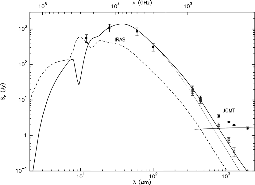
The results of our LTE analysis of the envelope in the last section can be compared with exact modeling of the envelope using calculations of the radiative transport in dusty shells (DIRT: http://dustem.astro.umd.edu, Wolfire et al. 1986; DUSTY, Ivezić et al. 1999). For the DUSTY modeling we used a 30000 K black body as radiation source, a mixture of Draine & Lee (1984) silicates and graphite with a standard MRN grain size distribution, and a dust temperature of 800 K at the inner boundary. The density structure was derived within DUSTY from full dynamics calculations. The remaining free parameters are the optical depth and the thickness of the envelope. Fig. 7 shows the model results compared to measured IRAS and JCMT flux densities (Knapp, Sandell & Robson 1993). The optical depth determines the overall shape of the SED, whereas the thickness s=r(out)/r(in) only modifies the submm part of the SED. We subtracted the free-free contribution originating from the HII region (cf. Sect. 3.3) from the submm emission. The SED shape of the DUSTY models is independent of the luminosity, which just scales the model fluxes up or down. An adequate fit to the data is reached using , a thickness s and a luminosity of . r(in) is the dust sublimation radius which is for this model at 0.11 arcsec, hence this is the same radius we used in the last section. The outer radius r(out) of 330 arcsec is comparable to the 400 arcsec observed by Speck et al. (2000) with ISO. As seen in the Figure, a smaller outer radius can reproduce the submillimeter flux densities.
While these results are interesting in their own right, for our interpretation of the vibrationally excited lines only the inner part of the envelope is relevant and especially the high optical depths of the envelope. We checked the inner temperature structure (thickness s10) of DUSTY and DIRT models with the high optical depth to fit the SED and found that the temperature falls off considerably faster than in the optical thin case. While the exact structure of the models differ they can roughly be approximated with =–0.8 power laws, hence consistent with the results of the last section.
Since DUSTY allows us also to model the envelope expansion by assuming that it is driven by radiation pressure on the dust grains (Ivezić & Elitzur 1995, Elitzur & Ivezić 2001), we can compare the velocity structure predicted by DUSTY with our results from the last section. The model used to fit the SED leads to a terminal wind velocity of 4 km/s for a gas-to-dust ratio and a dust grain bulk density g/cm3. scales with (see Elitzur & Ivezić 2001 for details). Hence, explaining a of order 20 km/s, as implied by our data, would require very unlikely values for and/or . But even then, the P Cygni profiles predicted by a DUSTY velocity structure would be very broad and less peaked than the observed ones. The reason is that for radiatively driven, optically thick winds most of the acceleration takes place in a very thin part of the shell: 90% of is reached already at about 2 . We therefore conclude that the expansion of the CRL 618 envelope cannot exclusively be due to radiation pressure and other processes have to be invoked, e. g. processes related to the powerful outflow associated with CRL 618.
4.6 The total absorbing column density and the ratio
The observed absorption lines can be used to estimate the column density on the line of sight. As discussed in the last section, the major uncertainty here is the partition function. We use again two extreme cases to constrain the column density: using a temperature of 520 K (Sect. 4.3) the column density is 3–6 .
To estimate the ratio to a high accuracy, we determined the minimum -sum between data and model for the and the lines. These lines were chosen, because they appear to be unblended and were observed simultaneously with the same receiver. Hence, in the ratio, all calibration uncertainties cancel out. Appearing mostly in absorption, these 3mm lines are much more sensitive to column density than the corresponding lines at the higher frequencies. The errors in the resulting densities were determined by varying the densities around the best fit values. This leads to a ratio of and the model fits to all of the lines are shown in Fig. 8.
5 Discussion and Conclusions
Our results include the best determination of the temperature structure in CRL 618 so far. The method we used offers several advantages: (i) highly excited absorption lines of in vibrationally excited states are able to probe the hottest, inner part of the molecular envelope in a pencil beam. Since vibrationally excited lines with the same are observed simultaneously, their relative calibration is excellent and the peak temperature found is K. (ii) Due to the expansion of the envelope, the temperature structure can be determined as a function of velocity. (iii) From the emission part of the observed P Cygni spectra the spatial extend of the envelope at a certain velocity can be determined, which leads then to temperature structure as a function of radius ().
How does our result compare with previous measurements? Cernicharo et al. (2001) find a temperature of 200 K from their ISO mid-infrared observations of HCN and . They were not able to resolve the velocity structure and therefore probe with their absorption lines an average over the whole line of sight, hence a lower temperature. In the analysis of far-infrared ISO observations of CRL 618 Herpin & Cernicharo (2000) distinguish between different shells close to the central star, with temperatures of 1000, 800 and 250 K, decreasing away from the star with radii of 0.3, 0.5 and 0.8 arcsec, respectively. The shells with the higher temperatures than our estimate seem to probe a photon dominated region, where might not be able to exist yet.
Exact modeling of the dusty circumstellar envelope using DUSTY was able to reproduce the temperature structure and the spectral energy disribution, but failed to predict the observed velocity structure of the envelope, indicating that radiation pressure alone is not sufficient to drive the expansion.
Isotopic abundance ratios in AGB stars deliver, in principle, valuable information on nuclear processes and dredge-up convective processes that bring up enriched material into the stars’ outer layers from where they finally end up in the circumstellar envelopes (see, e.g. Balser, McMullin & Wilson 2002 and references therein). The abundance ratio of 10 we determine is much lower than the solar system value of 89. Our ratio is very similar to the ratio of 11.6 derived by Wannier & Sahai (1987) for CRL 618, which is the lowest they found for any of the ten C and one S stars they investigated. The ratios for the other stars in their sample range from 14 to 48. In contrast, Kahane et al. (1992) derive = 18 and 3.2 for the 1-0 and 2-1 rotational lines, respectively, for CRL 618. However, they adopt a lower limit of 30 for , which they derive from the double ratio. From carbon monoxide observations, Balser et al. (2002) determined the ratio for 11 planetary and protoplanetary nebulae and found values between 4 and 32, with a lower limit of 4.6 for CRL 618 being at the lower end.
There are thus a number of uncertainties in the determination of the in CRL 618. However, observations of C-bearing molecules other than carbon monoxide should be useful to get a clearer picture since they might be subjected differently to fractionation and photodissociation than the CO isotopomers, where, according to Kahane et al. (1992) these processes cancel each other.
Appendix A The HC3N Partition Function
The partition function can be written as the product of its vibrational and rotational part:
| (A1) |
In cold gas the contribution of vibrationally excited states can be neglected and for linear molecules the partition function is simply . In hotter environments molecules are excited into vibrational states and is given in LTE as
| (A2) |
where the sums can be evaluated analytically to yield:
| (A3) |
(Herzberg 1945). Here is the vibrational quantum number and denotes the degree of degeneracy of vibration with vibrational frequency of .
For non-LTE conditions, the higher levels might not be populated for two reasons: 1.) critical densities for the higher levels are generally larger so that the density might be too small to populate the level. 2.) Vibrationally excited states might be excited by infrared radiation fields. Higher levels correspond to shorter wavelengths in the NIR, where the radiation might be too weak to pump the levels. Hence, to estimate a lower limit for the partition function we computed Eq. A2 only up to the highest energy observed. The resulting lower and upper limits for the vibrational part of the partition function as a function of temperature are shown in Fig. 9, together with values from laboratory measurements published in the Cologne Database for Molecular Spectroscopy (CDMS, http://www.cdms.de/, Müller et al. 2001).
Appendix B The Radiative Transfer
To calculate the intensity at a certain position and velocity , we integrate over the line of sight at :
| (B1) |
with
| (B2) |
Here, is the intensity integrated up to a position on the line of sight. is the source function at a position . is either the kinetic temperature of the molecular gas or the electron temperature of the embedded HII region. The optical depths at any position is given as:
| (B3) |
with
| (B4) |
and the population of the upper states in LTE:
| (B5) |
The optical depth through the HII region is:
| (B6) |
References
- (1) Balser, D. S., McMullin, J., P. & Wilson, T. L. 2002, ApJ, 572, 326
- (2) Bujarrabal V., Gomez-Gonzalez J., Bachiller R., Martin-Pintado J. 1988, A&A 204, 242
- Cernicharo et al. (1989) Cernicharo, J., Guelin, M., Penalver, J., Martin-Pintado, J., & Mauersberger, R. 1989, A&A, 222, L1
- Cernicharo et al. (2001) Cernicharo, J. ;, Heras, A. M., Tielens, A. G. G. M., Pardo, J. R., Herpin, F., Guélin, M. & Waters, L. B. F. M. 2001, ApJ, 546, L123
- (5) Draine, B.T. & Lee, H.M. 1984, ApJ 285, 89
- Elitzur & Ivezić (2001) Elitzur, M. & Ivezić, Željko 2001, MNRAS, 327, 403
- Hajian, Phillips, & Terzian (1995) Hajian, A. R., Phillips, J. A., & Terzian, Y. 1995, ApJ, 446, 244
- Herpin & Cernicharo (2000) Herpin, F. & Cernicharo, J. 2000, ApJ, 530, L129
- (9) Herzberg G. 1945, Vol.2 - Infrared and Raman Spectra of Polyatomic Molecules.
- (10) Hrivnak B.J. 1997, in Planetary Nebulae, IAU 180, eds. Habing & Lamers
- Ivezic & Elitzur (1995) Ivezić, Z. & Elitzur, M. 1995, ApJ, 445, 415
- Ivezic & Elitzur (1996) Ivezić, Z. & Elitzur, M. 1996, MNRAS, 279, 1011
- (13) Ivezić, Z., Nenkova, M. & Elitzur, M., 1999, User Manual for Dusty, University of Kentucky Internal Report, accessible at http://www.pa.uky.edu/moshe/dusty
- Kahane, Cernicharo, Gomez-Gonzalez & Guelin (1992) Kahane, C., Cernicharo, J., Gomez-Gonzalez, J. & Guelin, M. 1992, A&A, 256, 235
- Knapp, Bowers, Young, & Phillips (1995) Knapp, G. R., Bowers, P. F., Young, K., & Phillips, T. G. 1995, ApJ, 455, 293
- Knapp, Sandell, & Robson (1993) Knapp, G. R., Sandell, G., & Robson, E. I. 1993, ApJS, 88, 173
- (17) Kwan J., & Linke R. A. 1982, ApJ, 254, 587
- Kwok & Feldman (1981) Kwok, S. & Feldman, P. A. 1981, ApJ, 247, L67
- (19) Kwok S., Bignell R.C. 1984, ApJ 276, 544
- (20) Kwok S. 1993, ARAA 31, 63
- (21) Mamon, G. A., Glassgold, A. E., & Huggins, P. J. 1988, ApJ, 328, 797
- (22) Martin-Pintado J., Gaume R., Bachiller R., Gomez-Gonzalez J., Planesas P. 1988, A&A 197, L15
- (23) Martin-Pintado J., Bachiller R., 1992, ApJ 391, L97
- (24) Martin-Pintado J., Bujarrabal V., Bachiller R., 1993, ApJ 419, 725
- (25) Meixner M., Campbell M.T., Welch W.J., Likkel L. 1998, ApJ 509, 392
- (26) Millar, T. J., Herbst, E., Bettens, R. P. A. 2000, MNRAS 316, 195
- (27) Müller H.S.P., Thorwirth S., Roth D.A., and Winnewisser G. 2001, A&A, 370, L49
- (28) Neri R. et al. 1992, A&A 262, 544
- Speck, Meixner, & Knapp (2000) Speck, A. K., Meixner, M., & Knapp, G. R. 2000, ApJ, 545, L145.
- (30) Thorwirth S., Müller H.S.P. and Winnewisser G. 2001, Phys. Chem. Chem. Phys. 3, 1236
- (31) Thorwirth S., Müller H.S.P. and Winnewisser G. 2000, J. Mol. Spectrosc. 204, 133
- (32) Thorwirth S. 2001, PhD thesis, Uni. of Cologne
- (33) Thorwirth S. et al. 2002, ApJL submitted
- Trammell (2000) Trammell, S. R. 2000, ASP Conf. Ser. 199: Asymmetrical Planetary Nebulae II: From Origins to Microstructures, 147
- Turner & Terzian (1984) Turner, K. C. & Terzian, Y. 1984, AJ, 89, 501
- (36) Wannier, P. G. & Sahai, R. 1987, ApJ, 319, 367
- Westbrook et al. (1975) Westbrook, W. E., Willner, S. P., Merrill, K. M., Schmidt, M., Becklin, E. E., Neugebauer, G., & Wynn-Williams, C. G. 1975, ApJ, 202, 407
- (38) Wolfire, M. G. & Cassinelli, J. P. 1986, ApJ, 310, 207
- (39) Wyrowski F., Schilke P., Walmsley C.M. 1999, A&A 341, 882
- Yamamura, Shibata, Kasuga, & Deguchi (1994) Yamamura, I., Shibata, K. M., Kasuga, T., & Deguchi, S. 1994, ApJ, 427, 406
| Isotopomer | or | ||||||||
|---|---|---|---|---|---|---|---|---|---|
| (MHz) | (K) or () | () | () | ||||||
| 45490.314e | 0 | .170 (20) | 38 | .7 (13) | 11 | .4 (24) | |||
| 0 | .290 (50) | 16 | . 6 (6) | 14 | .1 (12) | ||||
| 45494.714e | 0 | .120 (20) | 27 | .2 (17) | 14 | .0 (41) | |||
| 45520.454e | 0 | .064 (14) | 28 | .1 (7) | 6 | .8 (15) | |||
| 45564.964e | 0 | .130 (10) | 27 | .3 (3) | 3 | .5 (9) | |||
| 45600.785e | 0 | .115 (16) | 27 | .1 (4) | 2 | .7 (5) | |||
| 45602.171e | 0 | .180 (16) | 31 | .8 (4) | 12 | .5 (11) | |||
| 45667.550e | 0 | .240 (40) | 30 | .8 (4) | 10 | .2 (10) | |||
| 45727.452e | 0 | .040 (20) | 27 | .7 (7) | 6 | .6 (11) | |||
| 45729.306e | |||||||||
| 45779.054e | 0 | .080 (30) | 28 | .9 (2) | 7 | .3 (3) | |||
| 45856.001e | 0 | .096 (18) | 27 | .5 (4) | 3 | .7 (7) | |||
| Isotopomer | Frequency | or | |||||||
|---|---|---|---|---|---|---|---|---|---|
| (MHz) | (K) or () | () | () | ||||||
| 109023.305 | 0 | .220 (30) | 27 | .6(2) | 3 | .7 (3) | |||
| HC13CCN | 109125.744e | 0 | .120 (30) | 28 | .5(4) | 3 | .7 (9) | ||
| HCC13CN | 109139.707e | 0 | .150 (30) | 29 | .0(4) | 6 | .2 (8) | ||
| 109173.634e | 0 | .860 (20) | 20 | .4(1) | 17 | .6 (1) | |||
| 109173.634e | 0 | .100 (10) | 14 | .0(14) | 124 | .0 (50) | |||
| 109244.222 | 0 | .330 (50) | 28 | .9(2) | 5 | .6 (4) | |||
| 0 | .040 (10) | 19 | .6(8) | 7 | .9 (19) | ||||
| 109306.704e | 0 | .150 (30) | 27 | .1(4) | 2 | .7 (9) | |||
| 109352.781e | 0 | .420 (50) | 30 | .4(3) | 6 | .0 (5) | |||
| 0 | .090 (10) | 22 | .2(6) | 9 | .8 (14) | ||||
| 109469.409e | 0 | .100 (30) | 27 | .5(4) | 4 | .1 (8) | |||
| Isotopomer | Frequency | or | |||||||
|---|---|---|---|---|---|---|---|---|---|
| (MHz) | (K) or () | () | () | ||||||
| HC13CCN | 136404.396e | 0 | .166 (21) | 28 | .9 (8) | 4 | .9 (12) | ||
| 0 | .060 (10) | 19 | .8 (7) | 5 | .6 (12) | ||||
| HCC13CN | 136421.848e | 0 | .094 (25) | 29 | .7 (22) | 5 | .6 (34) | ||
| 0 | .050 (10) | 19 | .7 (10) | 7 | .2 (16) | ||||
| 136464.411e | 0 | .900 (20) | 20 | .6 (1) | 16 | .5 (3) | |||
| 136464.411e | 0 | .200 (20) | 21 | .9 (10) | 97 | .6 (33) | |||
| 136551.798 | 0 | .306 (39) | 29 | .5 (5) | 5 | .3 (9) | |||
| 0 | .100 (10) | 20 | .3 (8) | 5 | .9 (16) | ||||
| 136688.252e | 0 | .336 (45) | 31 | .3 (10) | 6 | .2 (16) | |||
| 0 | .140 (20) | 19 | .0 (8) | 8 | .8 (13) | ||||
| Isotopomer | Frequency | or | |||||||
|---|---|---|---|---|---|---|---|---|---|
| (MHz) | (K) or () | () | () | ||||||
| HC13CCN | 209137.396 | 0 | .110 (30) | 20 | .6 (8) | 10 | .1 (16) | ||
| HCC13CN | 209164.141 | 0 | .130 (30) | 21 | .6 (7) | 9 | .1 (12) | ||
| 209230.234 | 1 | .120 (50) | 20 | .8 (1) | 17 | .6 (4) | |||
| 209230.234 | 0 | .370 (50) | 20 | .6 (10) | 94 | .6 (33) | |||
| 209362.113 | 0 | .260 (40) | 20 | .3 (4) | 11 | .3 (9) | |||
| 209573.178 | 0 | .320 (40) | 20 | .9 (4) | 10 | .2 (8) | |||
| HC13CCN | 209597.019a | 0 | .040 (20) | 20 | (2) | 9 | (2) | ||
| 209628.074a | |||||||||
| 209661.546a | |||||||||
| HCC13CN | 209634.224a | ||||||||
| 209663.206a | |||||||||
| 209694.908a | |||||||||
a Line parameters were kept the same for all lines
| Frequency | Flux | Error |
|---|---|---|
| (GHz) | (mJy) | (mJy) |
| 4.5b | 26 | 3 |
| 20.2b | 425 | 60 |
| 24.7b | 490 | 90 |
| 34.8b | 680 | 140 |
| 34.8c | 740 | 140 |
| 40.8b | 750 | 75 |
| 45.6a | 800 | 200 |
| 47.2b | 840 | 85 |
| 82.3c | 1650 | 400 |
| 109.2a | 1800 | 200 |
| 136.5a | 1650 | 300 |
| 209.0a | 1350 | 340 |
a this study
b Thorwirth et al. (2002)
c Thorwirth (2001)
| Description | Parameter | Value |
| Temperature | 560 K | |
| –0.8 | ||
| Density | 500 – 1000 | |
| –4 – –5 | ||
| Velocity | –24.2 | |
| 3.3 | ||
| 1.6 | ||
| 4 | ||
| 10 | ||
| Hii region | 20900 K | |
| cm-6pc | ||
| 0.11″ |