Active Optics on the Baade 6.5-m (Magellan I) Telescope
Abstract
The Magellan active optics system has been operating continuously on the Baade 6.5-m since the start of science operations in February 2001. The active optical elements include the primary mirror, with 104 actuators, and the secondary mirror, with 5 positional degrees of freedom. Shack-Hartmann (SH) wavefront sensors are an integral part of the dual probe guiders. The probes function interchangeably, with either probe capable of guiding or wavefront sensing. In the course of most routine observing stars brighter than 17th magnitude are used to apply corrections once or twice per minute. The rms radius determined from roughly 250 SH spots typically ranges between 005 and 010. The spot pattern is analyzed in terms of a mixture of 3 Zernike polynomials (used to correct the secondary focus and decollimation) and 12 bending modes of the primary mirror (used to compensate for residual thermal and gravitational distortions). Zernike focus and the lowest order circularly symmetric bending mode, known affectionately as the “conemode,” are sufficiently non-degenerate that they can be solved for and corrected separately.
keywords:
active optices, wavefront sensing1 INTRODUCTION
Almost every major optical telescope of the current generation has an actively controlled primary mirror support system. No matter how much thought and care may have gone into the design of a telescope, the ultimate test is the quality of the images it delivers to the focal plane. Wavefront sensors can both monitor a mirror support system and provide feedback as needed. An excellent review of the use of such systems is given by Noethe[1].
The Magellan I (Baade) and II (Clay) telescopes have f/1.25 primaries, making the tolerances on the secondary position exceedingly tight. Furthermore the figures of the 6.5-m borosilicate primary mirrors are sensitive to temperature changes. Some 4 years before first light the decision was taken to incorporate wavefront sensors into the facility guiders, to ensure that focus, collimation and the figure of the primary mirror are maintained through the course of routine operations. At the Baade telescope it is standard procedure to acquire both a traditional guide star and a wavefront star for every observation.
While the Magellan active optics system is quite simple, it appears to work effectively and reliably. It may serve as an example of how little one can do and still produce good images. The primary mirror support system is described in §2. The guider is described in §3. Wavefront analysis is described in §4. Operation and performance are described in §5.
2 MIRROR SUPPORT SYSTEM
The primary mirror support for the Magellan telescopes is similar to that for the MMT, which is described in detail by Martin et al.[2] What follows is drawn from their more extensive discussion. Axial support is supplied by 104 pairs of opposed push-pull air cylinders, each with a load of N at zenith, under the control of a Motorola VME 68K computer running VXWORKS. These can be adjusted in N increments. Feedback is supplied by load cells located on three hard points, with an outer control loop nulling the forces on these. Changes due to gravity, telescope accelerations and wind loading are corrected with a bandwidth of 1 Hz.
A finite element analysis of the primary was carried out by BCV Progetti, showing how a force of N applied to each of the actuators influenced 3200 locations on the surface. The finite element analysis was verified in a series of tests at the Steward Observatory Mirror Lab, showing that the surface responds as expected to the forces applied. A singular value decomposition (SVD) was carried out to identify a sequence of “bending modes” ordered from softest to stiffest. Each bending mode consists of a set of forces and the correspoding displacement of the mirror. Both the force vectors and the surface displacements are orthogonal.111Our bending modes are similar to the minimum elastic energy modes discussed by Noethe[1]. They differ in that our SVD modes minimize forces on a discrete set of actuators rather than the elastic energy of the mirror.
The surface distortions of the low order modes correspond quite closely to Zernike polynomials, with the exception of the third softest (lowest order axisymmetric) mode. Martin et al. note that the surface deflection for this mode is more nearly conical than the paraboloidal shape expected for Zernike focus, and that it includes a substantial element of Zernike spherical aberration.
An early study showed that the forces required to produce low order Zernike polynomial displacements on the surface of the mirror could be very much reduced by restricting the force set to the 32 softest mirror modes, with very little loss in surface accuracy. During the first half year of operation, when we analyzed the wavefront in terms of Zernike polynomials, we projected the wavefront onto these low order modes and ignored the projections onto the stiffer modes in computing correction forces. We subsequently analyzed the wavefront directly in terms of the bending modes, using a yet smaller subset.

3 FACILITY GUIDERS
Two facility guiders are currently in operation at the f/11 Nasmyth focii of the Baade telescope, with two more to be installed on the Clay telescope by the end of 2002. Each telescope has three additional folded Gregorian ports. Eventually a total of six guiders will be mounted on the two telescopes for use with small and medium-sized instruments. Large instruments will have their own internal guider optics and wavefront sensors but will make use of the hardware and control software developed for the facility guiders.
The guiders, as shown in Figure 1, have two identical probe assemblies, symmetrically arranged, each consisting of a pickoff mirror, three 3-position cross-slides that carry optics, and a CCD camera. The cross-slides are moved by pneumatic pistons. The first cross-slide in the optical train is located at the conjugate telescope focus and lets the operator select either a field lens for direct guiding, an aperture for use with the wavefront analyzers, or a calibrator for the wavefront analyzer. The calibrator consists of a 100 micron pinhole and an LED illuminator. A filter slide with red and blue filters and an open position comes next in the optical train. The third slide carries a re-imaging lens for direct guiding and a choice of two wavefront analyzers for coarse and fine spatial sampling of the telescope pupil. The re-imaging lens is an Olympus Zuiko 50 mm macro lens that gives a 2.5:1 reduction at the CCD.
Each Shack-Hartmann wavefront analyzer consists of a 100 mm focal length collimating lens and a lenslet array. The collimating lens forms a 9 mm diameter image of the telescope pupil on the array. Currently the choice of arrays gives approximately 12 and 18 samples across the pupil for the “coarse” and “fine” analyzers respectively although in practice only the fine array is used. It has a pitch of 0.5 mm, a 30 mm focal length and a format that allows some motion of the pupil image as the probe moves around the field before the pupil falls off the array.
The probe assemblies are mounted on perpendicular x-y recirculating ball slides that allow the pick-off mirrors to move around the field of view. Ball screws with stepper motors and encoders control the slide positions. Each probe can cover a region 7.7 arcmin by 12.9 arcmin on its side of the guider. The regions overlap so that both probes have access to the center of the field. A focus mechanism with 25 mm travel between the pick-off mirror and the first cross-slide compensates for focal plane curvature. The instrument focus behind the guider assembly is nominally fixed at 125 mm.
Each CCD camera can be used for both direct guiding and wavefront analysis, depending upon the configuration of the probe cross-slides. Each camera has a thermoeletrically cooled, back-illuminated Marconi frame-store CCD with 13 m pixels. These are always binned . A total of 20 such cameras have been constructed for use in the facility guiders and in intrument specific applications. The guide cameras are controlled by PCs running DOS.
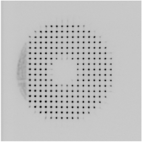
In Figure 2 we show a typical Shack-Hartmann image. As the probe is fairly close to the edge of the field, a portion of the pupil falls off the lenslet array.
4 WAVEFRONT ANALYSIS
4.1 Wavefront Errors
For stars with mag, we use a combination of on-chip integration and leaky-memory averaging to generate an effective integration time of about 30 s on Shack-Hartmann exposures. These are compared with a stored exposure of the calibration LED. Hot pixels are flagged but the data are not otherwise corrected for photometric sensitivity. A customized version of the stellar photometry program DoPHOT [3] is used to find the centroids and central intensities of all spots. In a first pass through the data a typical shape is determined for the point spread function (PSF). Spots that deviate significantly from this shape are excluded from further consideration. On a second pass through the data the typical PSF is then used for all spots. By fitting a model PSF rather than computing centroids, accurate spot positions can be obtained even when the data is corrupted by bad pixels.
A feature of our design is that the image of the pupil on the lenslet array moves off the center as the pickoff mirror moves away from the field center. The pupil center is determined from intensity measurements of those spots at the edge and center of the pupil formed by lenslets that are only partially illumnated. A model is fit to these to obtain the pupil radius and center, with the latter accurate to roughly 1 pixel.
Vector spot displacements relative to the reference LED exposure are measured in pixels. The positions of these spots, normalized by the pupil radius, are computed with respect to the pupil center. A set of basis functions, e.g. Zernike polynomials, is used to describe the wavefront. These are differentiated and the resulting slopes are used to obtain a best fit to the vector spot displacements (typically some 220 of them) using a linear least squares algorithm.222While Zernike polynomials are orthogonal, their gradients are not. The same holds true of the bending modes, as they are constructed from surface displacements rather than slopes. Nonetheless the covariances are small enough that the coefficients are well determined. The coefficients of the basis functions can be converted to wavefront errors using the parameters of the optical system.[1]
Without the wide-field corrector in the telescope, stars well off-axis show strong Zernike coma and astigmatism. We correct for these by subtracting predicted vector spot displacements from the observed displacements prior to fitting.
All of the above is carried out on a PC running Linux. The same machine serves as the telescope operator’s interface to the telescope control computer, a PC running DOS.
4.2 Correction
At least some of the errors in the wavefront arise from the displacement of the secondary mirror rather than the distortions of the primary mirror. In particular, we attribute the Zernike focus and coma terms to the secondary and adjust it accordingly. Ordinarily no correction is made for wavefront tilt (pointing), as this is usually under the control of the other guide probe. The remaining terms, 12 at present, are used to construct a surface error attributed to the primary mirror. Force adjustments are computed for the primary mirror actuators, and if the accumulated forces do not exceed a specified limit – typically 15% of the nominal force – the corrections are applied. If the force limit is exceeded, operator intervention is required.
The time to transfer a Shack-Hartmann exposure and compute corrections is roughly 5 s, during which time the next SH exposure is accumulating. Moreover the guide camera runs in a leaky average mode, with a time constant equal to the exposure time. We therefore set the steady state gain, the applied fraction of the computed corrections at 33%. When an object is first acquired, after a slew, the errors can be large. To minimize setup time we set the gain to 100% on the first exposure, and reset the guide camera after applying these corrections.
4.3 Operator Interface
The active optics software occupies one of four “desktops” on the operator’s monitor. The operator sees the most recently acquired SH image, with individual spot positions enclosed in green if a minimum number of points has been identified (almost always the case), and in red otherwise. A vector plot of spot displacements is also displayed. A spot diagram, computed from the displacement vectors, shows the size of the image the telescope would have produced in the absence of seeing, windshake, guiding errors and diffraction. The accumulated forces on the actuators are displayed graphically, as are the amplitudes of the accumulated corrections in each basis function.
A text window reports on the progress of each frame. The maximum force (relative to the nominal actuator forces) and rms spot size are also reported, as are the motions requested of the secondary. The amplitude of each basis function is given in terms of rms microns of wavefront. Typical values for astigmatism and focus might be 25 nm in each mode, with values decreasing into the small single digits for the highest modes fit.
4.4 Choice of Basis Functions
In our initial deployment we chose to expand the wavefront in terms of Zernike polynomials, as these were easy to compute and readily interpreted. Over the course of the first few months of science operations we found that our self-imposed force limits were frequently exceeded, with the largest forces due to accumulated spherical aberration. This typically occurred at the beginning of the night, and by midnight the spherical terms would usually disappear. Our attempts to make sense of this were inconclusive but we suspected that we might do better using the bending modes as basis functions rather than Zernike polynomials, which can be quite steep at the edge of the pupil.
Though the bending modes might be better for the primary mirror, Zernikes (focus and coma) are more appropriate for the secondary. We therefore switched to a hybrid scheme. At low order the Zernike polynomials and mirror modes are easily matched. They have similar topographies, with the same azimuthal structure and similar radial structure. It seemed likely that including both would cause the solution to be unstable. We adopted a flexible system in which one might fit for one or the other or (at some risk) both.
Zernike coma and its associated mirror mode look so much like each other that there was no hope of separating the two. We fit for Zernike coma and send corrections to the secondary. But as discussed in §2, Zernike focus and its associated mirror mode are different. Zernike focus has surface displacements that vary as the square of the pupil radius, with slope errors proportional to pupil radius. The vector field of slope errors therefore looks like the Hubble expansion of the universe. By contrast the surface displacements of the corresponding mirror mode vary very nearly linearly with radius. The slope errors, directed radially, all have the same length.
The fact that Zernike focus and its associated mirror mode can be distinguished means that they can be solved for separately. Of course one might not want to fit for the corresponding mirror mode – it might be quite stiff and not easily generated by errors in the support forces or thermal stresses. But in our case this “conemode” is the third softest, stiffer than the two astigmatic modes but softer than trefoil.
| bending | 2,0 | 0,0 | 3,0 | 1,1 | 4,0 | 2,1 | 5,0 | 0,1 |
|---|---|---|---|---|---|---|---|---|
| Zernike | astigmatism | focus | trefoil | coma | quadrafoil | 5th order astig. | pentafoil | spherical |
| used | 2,0 | both | 3,0 | coma | 4,0 | 2,1 | 5,0 | 0,1 |
This suggests a possible explanation for the large spherical aberration we measured. As noted by Martin et al.,[2] the conemode projects onto all circularly symmetric Zernikes, with the largest projection onto focus, a smaller projection onto spherical and so forth. Attempting to correct this conemode by focusing the secondary leaves a significant amount of uncorrected spherical and higher-order aberration. While Zernike focus may not be degenerate with the conemode taken alone, it will become increasingly degenerate with some linear combination of conemode and higher order circularly symmetric mirror modes as we add more of the latter. We have found empirically that our corrections are stable if we include only the next higher mode, which corresponds to Zernike spherical.
Reflecting the partial degeneracy between focus and conemode, the corrections computed for both of these are correlated. Suppressing the corrections for conemode would reduce the computed focus corrections by roughly a factor of two.
In Table 1 we show the mirror bending modes paired with the corresponding Zernike polynomials of the same symmetry. The modes are ordered from softest to stiffest. This ordering is similar to that of the NTT[1], but with the 1,1 and 4,0 modes permuted.
Switching to mirror modes reduced the spot size by a factor of 1.5, and the typical maximum force by roughly the same factor. The force limits are exceeded less frequently. When this does happen, it is the 0,1 bending mode (corresponding to spherical aberration) that produces the largest forces. Fitting for this term is disabled and typically re-enabled at the next pointing or a few hours later.
5 OPERATION AND PERFORMANCE


Figure 3 shows spot displacement patterns for two different SH images. The one on the left was the last one obtained at the end of a night. The one at the right was the first one obtained on the following night. The tick mark to the lower left shows a displacement of 02. The displacement field at the right is not simply the product of defocus, which would produce displacements proportional to distance from the center of the pupil.
These plots can be used to obtain a spot pattern. The typical rms spot pattern has an rms radius of 0075. The best spot patterns recorded have an rms of 0042. This includes errors in measuring spot positions.
The best optical exposures of 90s or longer obtained on the Baade telescope have had a FWHM of 030. It would therefore seem that the primary mirror and the position of the secondary contribute little to the degradation of the delivered image quality, even in the best conditions.
The active optics system operates sufficiently smoothly that some observers are unaware of its existence. Other, more experienced observers initially react with skepticism when they are told that they don’t need to focus the telescope. Probe offsets for each instrument, putting the aperture of the SH analyzer at the focus of the telescope, are measured and updated by the instrument specialists during engineering runs.
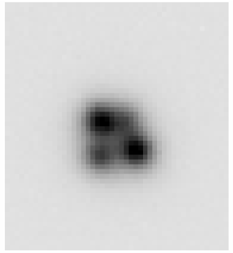
The end product is astronomical data. In Figure 4 we show a minute exposure of a quasar drawn from the Hamburg-ESO digital objective prism survey[4]. It is one of three HE quasars found to be gravitationally lensed in the first season of a survey with Magellan. An intervening galaxy produces a quartet of images, with the two brightest separated by 067. The PSF on this image has a FWHM of 041.
6 DISCUSSION
While the implementation of the Magellan active optics system has gone relatively smoothly, we learned some things in the process.
-
•
We found that we never use our coarse lenslet array. Even at high galactic latitude there is almost always a star bright enough to correct the wavefront with the fine array.
-
•
While the pupil runs off the the lenslet array at large field angles, the effect on correcting the wavefront seems minimal.
-
•
The use of bending modes rather than Zernike polynomials reduced the forces required to correct the wavefront and gave better correction.
-
•
With 18 Shack-Hartmann spots across the diameter of our pupil, we are able to correct simultaneously for three azimuthally symmetric wavefront terms: a focus term attributed to displacement of the secondary; a “conemode,” the lowest circularly symmetric bending mode of the primary; and the next softest bending mode corresponding roughly to spherical aberration, but with admixtures of focus and higher order modes.
In the future we hope to incorporate larger lenslet arrays, eliminating the current spillover. Another possible improvement would be use of SVD bending modes derived from mirror slopes rather than the surface displacements. These would give a set of basis functions that is more nearly orthogonal for use in reconstructing the Shack-Hartmann spot displacements.
Acknowledgements.
We thank Lothar Noethe for his counsel in the early stages of this effort. PLS gratefully acknowledges the support of the John Simon Guggenheim Memorial Foundation and the hospitality of the Institute for the Advanced Study.References
- [1] L. Noethe, “Active Optics in Modern, Large Optical Telescopes,” Progress in Optics), Vol. 43, (2002); preprint astro-ph/0111136.
- [2] H. M. Martin, S. P. Callahan, B. Cuerden, W. B. Davison, S. T. DeRigne, L. R. Dettmann, G. Parodi, T. J. Rebisky, S. C. West, and J. T. Williams, “Active supports and force optimization for the MMT primary mirror,” in Advanced Technology Optical/IR Telescopes, L. M. Stepp, ed., Proc. SPIE 3352, p.412 (1998).
- [3] P. L. Schechter, M. Mateo and A. Saha, “DOPHOT, a CCD photometry program: descripiton and tests,” Pub. Astr. Soc. Pac. 105, p.1342 (1993).
- [4] L. Wisotzki, N. Christlieb, N. Bade, V. Beckmann, T. Köhler, C. Vanelle, and D. Reimers, “The Hamburg/ESO survey for bright QSOs. III. A large flux-limited sample of QSOs,” Astron. Astrophys. 358, p.77. (2000).