Rayleigh Laser Guide Star Systems: UnISIS Bow Tie Shutter and CCD39 Wavefront Camera
Abstract
Laser guide star systems based on Rayleigh scattering require some means to deal with the flash of low altitude laser light that follows immediately after each laser pulse. These systems also need a fast shutter to isolate the high altitude portion of the focused laser beam to make it appear star-like to the wavefront sensor. We describe how these tasks are accomplished with UnISIS, the Rayleigh laser guided adaptive optics system at the Mt. Wilson Observatory 2.5-m telescope. We use several methods: a 10,000 RPM rotating disk, dichroics, a fast sweep and clear mode of the CCD readout electronics on a 10 s timescale, and a Pockel’s cell shutter system. The Pockel’s cell shutter would be conventional in design if the laser light were naturally polarized, but the UnISIS 351 nm laser is unpolarized. So we have designed and put into operation a dual Pockel’s cell shutter in a unique bow tie arrangement.
1 INTRODUCTION
The UnISIS Rayleigh laser guide star system has been commissioned as described in Thompson and Teare (2002). The system is built around a 30 Watt excimer laser that emits short 90 mJ pulses of 351 nm light at rates up to 333 Hz. These pulses are projected in the ”full- aperture broadcast” mode and are focused in the stratosphere at an altitude of 20 km above mean sea level ( 18 km above the telescope). Immediately after the outgoing pulse of laser light hits the telescope primary mirror, a bright flash of low altitude Rayleigh scattered light fills the near-field of the telescope. As described below, the science cameras can be shielded from this near-field burst of light by dichroics because the projection method – a 10,000 RPM rotating glass disk – blocks the adaptive optics system from seeing a large fraction of this light in the first few microseconds after the laser pulse. It is more difficult to protect the laser guide star wavefront camera because it is highly sensitive to the laser wavelength. We use two methods to accomplish the latter task: a continuous high speed read and flush of the CCD wavefront camera and a Pockel’s cell shutter.
We start in Sec. 2 with a general discussion of ways that other laser guide star projection systems handle the contaminating Rayleigh scattered light, and then we review the UnISIS rotating disk projection system. In Sec. 3 we describe briefly the dichroic isolation of the UnISIS science cameras. In Sec. 4 we describe how the UnISIS wavefront sensor is hidden from the low altitude near-field burst of Rayleigh light with our new bow tie Pockel’s cell shutter system, and then in Sec. 5 we describe the second level of protection for the wavefront sensor: a continuous high-speed read and flush mode of the UnISIS wavefront CCD. The general characteristics of the UnISIS CCD system and its future upgrades are also described in Sec. 5. An up to date block diagram of the UnISIS optical layout will be included in the next paper of this series, but a close approximation (not showing the bowtie shutter) can be found in Thompson et al. (1998).
2 LASER GUIDE STAR PROJECTION SYSTEMS
Sodium resonance line excitation at 589.3 nm is the primary alternative to Rayleigh laser guide stars, yet sodium laser guide star systems also suffer from low altitude Rayleigh contamination. Because astronomy-qualified sodium laser systems that have been built to date are continuous lasers (or at least quasi-CW), design alternatives are limited for hiding their low altitude contaminating Rayleigh scattered light. A commonly suggested scheme for sodium lasers is to project the laser beam from behind the Cassegrain secondary mirror with special purpose projection optics. Once this scheme is implemented, the Cassegrain secondary mirror will provide a natural shadow when low altitude Rayleigh light is viewed from the telescope focal plane. As laser guide star systems become more complex, with multiple laser beams projected from the same telescope, only the lowest parts of the Rayleigh scattered light can be hidden behind the Cassegrain mirror. The two simple (single laser guide star) sodium systems now in operation or close to it – at Lick and Keck Observatories – employ quasi-CW lasers, and the laser projector is a small collimator strapped to the side of each telescope. In these two cases, Rayleigh scattered light is visible in the telescope focal plane, but it appears projected off to the side of the science object. A focal plane mask blocks it out. With future multiple laser guide star systems with 1 arcmin to 2 arcmin fields of view, focal plane masking will not work, so the low altitude Rayleigh scattered light is likely to become an obstacle to the installation of multiple laser guide star systems based on CW sodium-wavelength lasers.
The advantages of the full aperture broadcast method of UnISIS were described by Thompson and Teare (2002) who termed the UnISIS system ”Stealth qualified” because the FAA has placed no restrictions on the use of the laser projection system, and they require no active countermeasures. At Mt. Wilson a major fraction of the 2.5-m primary mirror is used as the projector optic, and this feature of UnISIS helps to dilute the energy density at all points except at high altitude where the laser is focused. Given the expected size of the Cassegrain mirror on the next generation of Extremely Large Telescopes, laser projection optics nearly as large as the 2.5-m primary mirror at Mt. Wilson could be used. This would allow these systems to be Stealth qualified, too, and would hide the lowest portions of the outgoing Rayleigh scattered light in the shadow of the central Cassegrain obstruction. But for the present, the UnISIS ”Stealth” characteristic comes at the price of having Rayleigh scattered light projected onto the primary mirror of the telescope in full view of the science cameras.
The Rayleigh guide star system at Starfire Optical Range (Fugate et al., 1994) also used the telescope primary mirror to project a pulsed laser beam into the sky in full aperture broadcast mode. The polarized Starfire laser beam was injected into the telescope by placing a polarizing beamsplitter cube on the telescope’s optical axis. Light from a pulsed copper-vapor laser was directed into the side of this cube, and light from satellites and astronomical objects was viewed through it in a direct line along the telescope’s optical axis. Not surprisingly, the cube beamsplitter fluoresced continuously, and the background light it emitted prevented the Starfire system from seeing low surface brightness astronomical objects.
To avoid the fluorescence encountered in the Starfire system, UnISIS is designed to have as its beam-sharing element a 10,000-RPM rotating disk. Highly reflective and laser hardened multi-layer dielectric spots are deposited onto the front surface of a glass disk, and the laser light is reflected off these spots. In principle, no light enters the glass disk substrate. Two other effects are also at work. First, even if the substrate beneath the reflective spots glows by fluorescence (excited by photons that leak through the reflective spot), the fluorescing portion of the disk rotates off the optical axis. Second, for the short time that the spot remains on the optical axis (as the laser fires), it acts like a shutter to prevent near-field Rayleigh scattered light from entering the UnISIS adaptive optics system. The laser pulse length is 20 ns and the disk rotates completely out of the beam over a period of 100 s. For the first few microseconds (50 times longer than the laser pulse and at a time when the Rayleigh backscatter is the strongest) only a small fraction of the pupil opens as the reflective spot moves to the side. This shuttering action of the reflective spot helps to hold back the 351 nm photons for both the dichroic shield erected for protection of the science cameras and the electronic shutter used for the wavefront sensor CCD. For more details on the rotating disk design and its operation, see Thompson and Xiong (1995) and Thompson and Teare (2002).
3 HIDING THE SCIENCE CAMERAS FROM RAYLEIGH SCATTERED LIGHT
The first several optical elements in the UnISIS adaptive optics system are shared for both the science and the down-link UV laser guide star photons. The dichroic separation is made immediately after the UnISIS deformable mirror. At this point, the UV light is reflected off an optical surface coated with a multi-layer dielectric with peak reflectivity greater than 99.9% at 351 nm, and the longer wavelength science light passes through it. This special-order dichroic (Optical Coating Technologies, Inc., Easthampton, MA) is flat topped and 20 nm wide. Wavelengths longer than 400 nm are transmitted to the science focal plane, and we count on UV blocking filters (for the CCD science camera) and the lack of UV and blue sensor responsivity (for the near-IR camera) to suppress all laser guide star photons that manage to leak to the final science focal plane of UnISIS.
4 POCKEL’S CELL SWITCH AND THE BOW TIE
Much more care must be taken to prevent laser contamination in the UV wavefront section of UnISIS because there the optics are designed to have the highest possible UV throughput at 351 nm. As mentioned above, a two-stage plan was devised to block the low altitude Rayleigh scattered contaminating light. The first stage involves a Pockel’s cell shutter system designed by Crawford (2002). In brief, a Pockel’s cell shutter consists of two crossed polarizers with a Pockel’s cell switch sandwiched between them. When the Pockel’s cell is turned off, it has no effect on the light, and the crossed polarizers pass no light. When a precisely adjusted level of high voltage is applied to the Pockel’s cell’s birefringent crystal, all light entering the cell has its plane of polarization rotated 90o, so 100% of the light entering the first polarizer exits the second. The Pockel’s cell can be switched on and off in microseconds. A crucial part of a Pockel’s cell shutter design is to create a precisely collimated beam. Crawford (2002) reports that the level of collimation has to be within one part in 105 to produce good extinction.
In its first implementation, the Pockel’s cell switch used only 50% of the laser guide star return signal. The UnISIS excimer laser is unpolarized and a conventional Pockel’s cell switch requires a polarized input beam. When the UnISIS return laser guide star flux was first measured, this flux was too low to operate the wavefront sensor in closed loop. At that point it was obvious that some means would have to be devised to recover the lost 50% of the laser guide star signal. The bow tie design allows both polarizations to enter the wavefront camera.
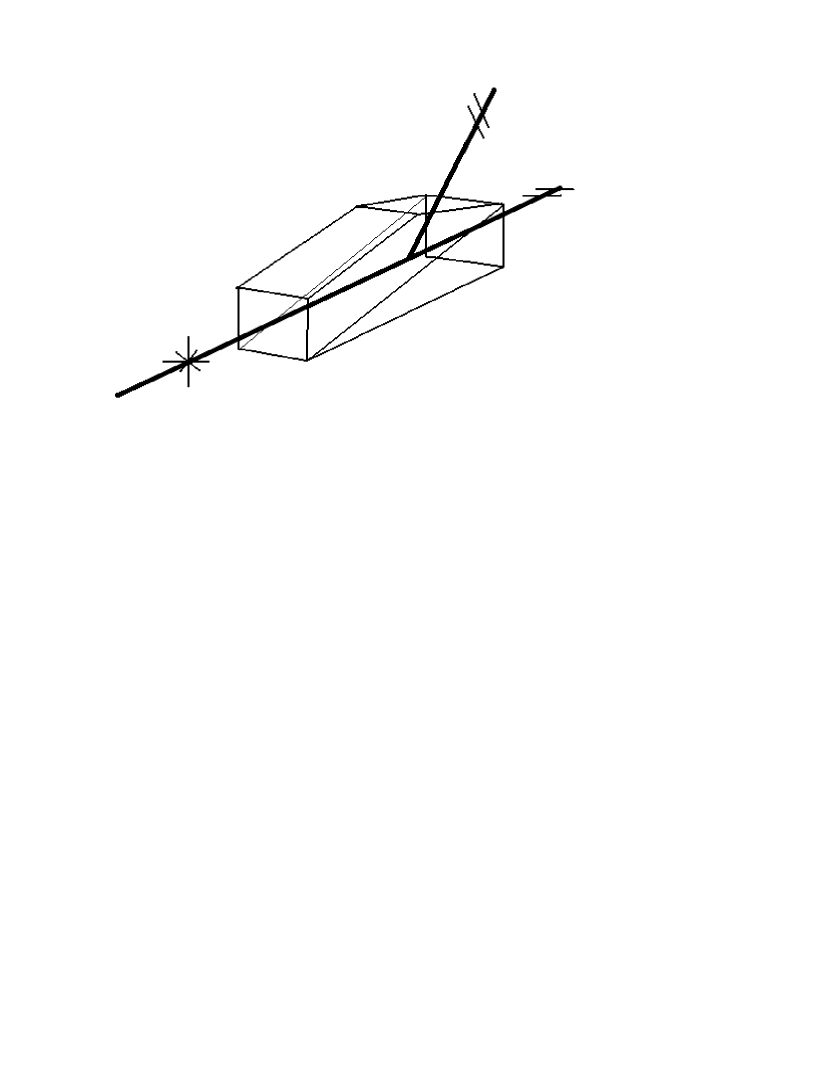
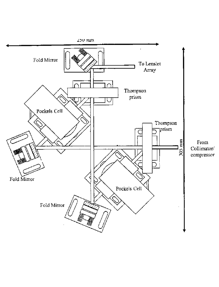
The bow tie is based on the birefringent properties of Thompson polarizers. Figure 1 shows the functional properties of a single Thompson polarizer which consists of two pieces of calcite cemented together and cut in such a way that one entering unpolarized beam produces two output beams, one of each polarization. These two beams emerge with an angular separation of 45o. Figure 2 shows a schematic drawing of the dual Pockel’s cell bow tie switch from Crawford (2002). Note that all optical components in Figure 2 sit in a precisely collimated portion of the UV wavefront optical train. The first Thompson prism, positioned at the entrance to the bow tie, works in a direct way to split the single entrance beam into two orthogonally polarized beams. The second Thompson prism, positioned at the exit of the bow tie, performs the reverse function of recombining the two polarized beams. The two separate paths through the bow tie satisfy the Pockel’s cell design requirement of having a Pockel’s cell sandwiched between two crossed polarizing elements.
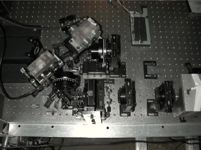
In Figure 2, the bow tie appears to be symmetric with the two beams exiting the first Thompson prism at exactly 45o. In reality, the angle is not exactly 45o because commercially available Thompson prisms are designed to work over a relatively broad wavelength range, and the calcite (like all optical materials) does not have the same index of refraction at all wavelengths. The calcite crystals are cut to make the angle between the two output beams close to 45o. Figure 3 shows the bow tie Pockel’s cell switch as it is implemented on the UnISIS optics table. Note the 180o reversal (top to bottom) between the design drawing and the implementation: the exit beam line is along the top of Figure 2 but along the bottom of Figure 3. The two Pockel’s cells were manufactured by Inrad Incorporated (Northvale, NJ) and are Model 212-150 with KD*P crystals. They are switched with a TTL pulse sent to a Q-switch driver, which is also from Inrad, Model 2-018 with high voltage adjustable up to 5 kV. The 1/4 wave phase delay occurs at approximately 3.5 kV with both Pockel’s cells.
The installation and alignment of the bow tie optical system required tremendous patience. The two output beams must be recombined with the two optical axes coincident and the beam directions identical. The pupil images must coincide to within a fraction of the 24m pixel size on the wavefront sensor. Attaining this adjustment is eased somewhat by a beam reduction between the 5 mm diameter collimated beam and the 0.936 mm pupil diameter on the wavefront CCD. The two collimated beams must match to 20 m. Once this alignment is achieved on the UnISIS optics table, it seems to hold for months.
Maximum extinction is reached when a Pockel’s cell is oriented exactly perpendicular to the local optical axis. A gross misalignment destroys the extinction, and a minor misalignment produces irregular pupil illumination. As installed in UnISIS, the bow tie produces a maximum extinction of 1000.
At the present time, the bow tie shutter has one deficiency: its front-to-back transmission is only 34% (i.e. a single leg of the bow tie transmits 17%). We plan to investigate three areas that might lead to improved throughput. First, each of the Thompson prisms consists of two pieces of calcite held together with cement. We suspect that the cement within the Thompson prisms might have unusually high absorbtion at 351 nm. Calcite is a natural product, and heavy element contaminants in optical materials absorb UV photons. Third, the 351 nm absorbtion might be high simply because the optical path length through the calcite is high. In its current configuration, the bow tie shutter requires each beam to traverse 2 x 30 mm of calcite.
In an alternate design for the bowtie shutter, the Thompson prisms could be replaced with Glan-Laser prisms. These prisms also split an unpolarized input beam into two polarized components and separate them by approximately 45o. Although Glan-Laser prisms are also made of calcite, the path length for each beam can be as small as 2 x 13 mm, and the two pieces of calcite are not cemented: they are separated by an air-space. A pair of Glan-Laser prisms placed at opposite corners of a parallelogram will mimic the function of the bowtie switch described here.
We recently tested the transmittance of a 10 mm square Glan-Laser prism provided by Nova Phase, Inc. (Newton, NJ). After accounting for the loss of light at the (currently uncoated) prism surfaces, the internal transmittance for this particular calcite prism was found to be 30 for a single polarization. This should be compared to a 17 transmittance for one leg of the current system with Thompson prisms. Finally, we note that a completely separate alternate strategy for shuttering the pulsed Rayleigh return signal is discussed at the end of Section 6.
5 WAVEFRONT SENSOR ELECTRONICS AND THE CCD39
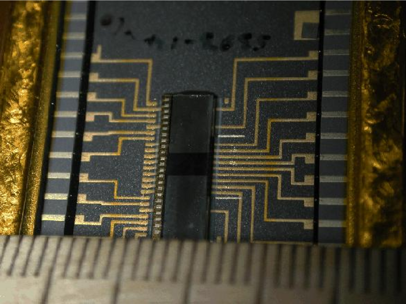
The Marconi CCD39 is well suited to wavefront sensing applications. It has a relatively small format at 80x80 pixels, 4 read-out amplifiers, relatively high UV quantum efficiency, and low amplifier read noise. The light sensitive area is 1.92x1.92 mm (see Figure 4). Because the flash of low altitude Rayleigh light is very bright, a significant level of contaminating light leaks through the Pockel’s cell shutter. To insure that the contaminating signal is gone by the time the return laser guide star light arrives 100s later, the following clearing process was implemented in the camera electronics (built by Astronomical Research Cameras Incorporated, San Diego, CA). When the CCD39 is not collecting an exposure, it is programmed to idle in a fast and continuous readout mode in which both parallel and serial registers on all four amplifiers are cleared. In this idle period, these registers are read-out at the full 10 MHz clock rate, and the output information is simply dumped. This process continues until the camera receives an external TTL signal, at which point the sensor is immediately reset and put into an integration mode.
As explained in Thompson and Teare (2002), a closed-loop wavefront correction cycle of UnISIS begins when a TTL pulse is created as an optical fiber detects the outgoing laser pulse. The TTL pulse is sent into a digital delay generator programmed to wait 100s before strobing the CCD39 which halts the CCD clearing mode and prepares the sensor to receive the laser guide star light. After the camera settles for about 10s, the Pockel’s cell shutter is opened for the time gate appropriate for the laser guide star return signal. The CCD39 then finishes its exposure, the camera readout begins, and this readout triggers the adaptive optics reconstructor computer to analyze the wavefront gradients from the Shack-Hartmann image it has just received.
Experimental tests of the CCD39 sensor with the Pockel’s cell shutter show that both systems (CCD clearing and Pockel’s cell extinction) are needed to hold back the Rayleigh backscatter flash. An example of the wavefront return signal from the Rayleigh laser guide star is displayed in Fig. 10 of Thompson and Teare (2002) where we display a single wavefront snapshot as well as the integrated sum of 45 consecutive exposures from a 20 Hz duty-cycle experiment. In this experiment, the original UnISIS CCD39 sensor was being used with its 48% quantum efficiency and a read noise of 4.4e- rms at a 3.2s per pixel read rate. A new sensor is now available with 68% quantum efficiency, and because the new sensor has a somewhat higher amplifier responsivity, we anticipate the same or perhaps lower read noise with the new sensor. Mt. Wilson is a site where RF interference is a problem, so it was a major accomplishment to get the CCD39 to perform at the 4.4e- r.m.s. noise levels. This is the same performance we see in an RF-free lab setting. By trial and error we found that the lowest noise was achieved when the camera and electronics were completely isolated from all ground planes.
In its current configuration, the UnISIS wavefront sensor works at a maximum frame rate of 833 frames per second giving a frame to frame latency of 1.2ms in closed-loop operation. Note that the per pixel dwell time of 3.2s mentioned above applies only to the 13x13 array of active Shack-Hartmann quadcells (each 2x2 pixels), so the actual read time for the active pixels is 0.54s. The camera electronics consume the remaining 0.7s. New timing board electronics now available through Astronomical Research Cameras Incorporated will allow the UnISIS CCD camera frame rate to increase to 1360 frames per second for a frame-to-frame latency of 735s. This upgrade will significantly improve the closed-loop performance of UnISIS on nights when the atmospheric turbulence has a short timescale.
The 13x13 quadcells used by UnISIS are distributed over an area on the sensor that spans 38x38 pixels because guard rows and guard columns separate each active 2x2 quadcell to prevent spillover. During a read-out cycle of the exposed frame, the guard columns and rows are skipped and the data are dumped at a high rate much like the clearing mode described above. A map of the active pixels superimposed on the 80x80 sensor geometry is shown in Figure 5 (reproduced from Thompson et al. (1998)).
6 SUMMARY
Laser guided adaptive optics is still in an early phase of development, and there are many ways yet to be found to configure both the lasers and the cameras to minimize interference from the inevitable low-altitude Rayleigh scattered light, whether this comes from sodium resonance laser guide stars or from Rayleigh laser guide stars. We have presented here several examples of how this is accomplished in UnISIS. We find that the greatest design flexibility comes with pulsed lasers rather than CW systems, and one of the more significant characteristics of the system design is whether aircraft and satellite avoidance can be handled in a fashion that can be called ”Stealth”. Pulsed lasers at 351 nm provide a distinct advantage in both regards. However, new technological innovations will continue to alter the balance for some time to come. One simple example is the potential ability of embedding the shutter function in the silicon substrate of the wavefront sensor CCD, thereby making Pockel’s cell switching unnecessary. MIT / Lincoln Laboratory has the ability to produce sensors of this type, but no UV sensitive versions are currently available for wavefront sensing (Reich, 2002). Other technological advances will, no doubt, come along as laser guided adaptive optics systems mature.
A number of people have contributed to the work reported here. This includes Richard Castle, Dr. E. Harvey Richardson and Bill Knight and his machine shop crew. At Mt. Wilson Observatory we acknowledge support provided by Mount Wilson Institute Director Dr. Robert Jastrow and technical assistance by Robert Cadman, Sean Hoss, Chris Hodge, Joe Russell, Victor Castillo and Thomas Schneider of Schneider Engineering. Telescope operator support at the 2.5-m telescope was provided by Kirk Palmer, Michael Bradford, and Jim Strogen. Marconi CCD39 wavefront software support was provided by Jamie Erickson and Scott Striet. The Pockel’s cells used in UnISIS were supplied by ThermoTrex Incorporated (San Diego, CA) as part of a surplus equipment transfer, and we thank Dr. David Sandler for assistance in that transfer. This work was supported by grants from the National Science Foundation: AST-9220504, AST-0096741 and by funds from both the University of Illinois and the New Mexico Institute of Mining and Technology. All support is very gratefully acknowledged.
References
- Crawford (2002) Crawford, S.L., M.S. Thesis, University of Illinois, unpublished.
- Fugate et al. (1994) Fugate, R.Q., Ellerbroek, B.L., Higgins, C.H., Jelonek, M.P., Lange, W.J., Slavin, A.C., Wild, W.J., Winker, D.M., Wynia, J.M., Spinhirne, J.M., Boeke, B.R., Ruane, R.E., Moroney, J.F., Oliker, M.D., Swindle, D.W., and Cleis, R.A. 1994, JOSA-A, vol. 11, 310-324
- Reich (2002) Reich, R. (2002), private communication.
- Thompson et al. (1998) Thompson, L.A., Castle, R.M., Teare, S.W., McCullough, P.R., and Crawford, S.L. 1998, Proc. SPIE, 3353, 282-289
- Thompson and Teare (2002) Thompson, L.A. and Teare, S.W. 2002. PASP, (September issue)
- Thompson and Xiong (1995) Thompson, L.A. and Xiong, Y.-H. 1995, Proc. SPIE, 2534, p. 38-47