A Coronagraph with a Band-Limited Mask for Finding Terrestrial Planets
Abstract
Several recent designs for planet-finding telescopes use coronagraphs operating at visible wavelengths to suppress starlight along the telescope’s optical axis while transmitting any off-axis light from circumstellar material. We describe a class of graded coronagraphic image masks that can, in principle, provide perfect elimination of on-axis light, while simultaneously maximizing the Lyot stop throughput and angular resolution. These “band-limited” masks operate on the intensity of light in the image plane, not the phase. They can work with almost any entrance pupil shape, provided that the entrance pupil transmissivity is uniform, and can be combined with an apodized Lyot stop to reduce the sensitivity of the coronagraph to imperfections in the image mask. We discuss some practical limitations on the dynamic range of coronagraphs in the context of a space-based terrestrial planet finder (TPF) telescope, and emphasize that fundamentally, the optical problem of imaging planets around nearby stars is a matter of precision fabrication and control, not Fraunhofer diffraction theory.
1 INTRODUCTION
The recent flood of indirect detections of extrasolar planets (Marcy et al., 2001; Schneider, 2001)111These websites about extrasolar planets are available at http://exoplanets.org/ (Marcy et al. 2001) and http://www.obspm.fr/planets (Schneider 2001). inspires us to search for an extrasolar planet that might be capable of supporting human life. Both NASA (Beichman et al., 1999) and the European Space Agency (Fridlund, 2000) have encouraged research into the design of a space telescope specialized for this purpose, a Terrestrial Planet Finder (TPF).
To detect an Earth-like planet orbiting a nearby star requires a telescope capable of unprecedented dynamic range. Initial TPF designs have concentrated on large-baseline interferometers operating in the mid-infrared, where the contrast between an earth-like planet and a sun-like star is minimal, about (Beichman et al., 1999). The expected planet/star contrast is a more daunting at visible wavelengths, i.e., 0.3–1.1 m.
However, a TPF operating at visible wavelengths offers several advantages. At shorter wavelengths, a smaller telescope can obtain the required diffraction-limited resolution; a 10 m baseline at 0.5 m yields the same resolution as a 200 m baseline at 10 m. Optical detectors require much less thermal control than infrared detectors, reducing the need for onboard cryogen and thermal shielding; a visible-light telecope may operate at room temperature, while a telescope operating in the thermal infrared must be cooled to K. Conventional optical telescopes form images, while an infrared interferometer coupled to a single mode of the radiation field focuses all the light in the interferometer beam onto a single detector pixel; this distinction makes an optical TPF relatively immune to background noise from exozodiacal dust. Finally, the pair of biomarkers, O2 and O3, available at visible wavelengths, appears to be more useful than the single biomarker, O3, available in the mid-infrared (Traub & Jucks, 2001; Des Marais et al., 2002).
The visible-light TPF designs proposed to date may all be loosely classified as coronagraphs. A traditional coronagraph is a device that sends a wavefront through two focii, an image plane and a pupil plane, before it forms the final image, so occulting masks strategically placed in the light path can control how the net instrument transfer function varies over the image plane. Not all TPF designs use occulting masks, allowing them to possibly dispense with some optical surfaces that a complete coronagraph would include. However, the formal description of the propagation of light through a coronagraph also describes these mask-less designs.
A conventional coronagraph typically uses a telescope which has not been optimized for coronagraphy, with an ordinary circular or obstructed circular aperture. The telescope focuses light onto an occulting mask which is transparent except near the optical axis, where it becomes opaque, to block the incoming on-axis light. The pupil is then re-imaged onto a Lyot stop, which is transparent near its center, but opaque near its edge to block light diffracted by the occulting mask (Lyot, 1939).
Unfortunately, to achieve the necessary dynamic range a few diffraction widths from the optical axis with a circular aperture and a traditional graded on-axis occulting mask requires a Lyot stop that blocks of the entrance pupil. To get around this stumbling block, some visible-light TPF designs invoke specially shaped pupils to separate starlight from planet light, or pupils with nonuniform transmissivity (Nisenson & Papaliolios, 2001; Spergel, 2001; Kasdin et al., 2001). We refer to pupils with nonuniform transmissivity as apodized pupils. Other coronagraph designs (Guyon et al., 1999) involve masks that must directly manipulate the phase of the light they transmit.
We show here that a conventional coronagraph with a graded pupil plane mask can, in principle, provide arbitratily large dynamic range without need for phase control or a severe Lyot stop. We describe a class of occulting masks and matching Lyot stops that can work in conjunction with any un-apodized entrance pupil to completely block the light from an on-axis source. Following this exposition, we consider some of the practical limitations on the dynamic range of coronagraphs in the context of TPF.
2 CORONAGRAPHY
The basic theory of coronagraphy has been discussed elsewhere (Noll, 1976; Wang & Vaughan, 1988; Malbet, 1996; Sivaramakrishnan et al., 2001), but we review it here to establish our notation. Let us assume that the telescope primary has a size scale , and that we are working at a wavelength . These two physical scales will almost always appear in combination, so we will frequently use the abbreviation . The coordinates in the pupil plane will be , and the coordinates in the image plane will be . In general, the hat accent will denote Fourier conjugation, i.e. . Quantities without a hat reside in the pupil plane; quantities with a hat reside in the image plane. We will work primarily in the pupil plane.
Consider an electromagnetic wave incident on an optical telescope. Explicitly, we would write that the field is a vector with magnitude
| (1) |
where , is the wave’s angular frequency, is time, and the wave propagates in the direction of the -axis. Hereafter, we will drop all factors of , and we will refer to the incoming field as . The intensity of light associated with this field is proportional to .
The wave first encounters the telescope’s primary mirror, which has aperture function , so that it transmits a field . The telescope then forms an image from this transmitted field. Assuming Fraunhofer diffraction applies, we can write the image field as , where denotes convolution.
In a coronagraph, the image is focused on an occulting mask with amplitude transmission factor (ATF) denoted by , and intensity transmission factor (ITF) equal to . A mask ATF may be negative or even complex, but if a mask is to operate on the intensity of light and not its phase, its ATF must be real, . The mask opacity is .
After the occulting mask, the field is . Successive optics in the coronagraph transform this product to a second pupil plane, where the field is . Now the field passes through a Lyot stop, which can be described by an aperture function . The final field has an amplitude . This field is re-imaged onto a detector, which detects the image’s intensity.
Notice that without an occulting mask (), the coronagraph has a transfer function . In this case, the Lyot stop and the aperture stop are redundant and they could be interchanged without affecting the final image. However, if is not a constant then interchanging the Lyot stop and the aperture stop will generally alter the final image.
3 A ONE-DIMENSIONAL EXAMPLE
We will illustrate how a coronagraph treats on-axis light by following the propagation of an incoming plane wave through a coronagraph. For simplicity, we will treat a one-dimensional coronagraph, and restrict ourselves to functions of and . For on-axis light, is a constant; for our one-dimensional example, we chose . We represent the telescope pupil, , with a tophat aperture, where the tophat function is for , and elsewhere.
We prefer to visualize the operation of a coronagraph entirely in the pupil plane. Note that the mask ATF, , which multiplies the electric field, is an image plane quantity. We prefer to plot the conjugate of the mask ATF, , a pupil-plane quantity.
Figure 1 illustrates the operation of a conventional one-dimensional coronagraph using the same example discussed at length in Sivaramakrishnan et al. (2001). Figure 1a shows the incoming field, multiplied by the telescope pupil. Since the incoming field is , this quantity is just .

In a conventional coronagraph, the occulting mask is a dark spot at the optical axis. We have chosen a simple Gaussian mask ATF
| (2) |
to represent this dark spot. The mask ITF associated with this function is
| (3) |
Figure 1b shows the conjugate of this mask’s ATF,
| (4) |
where is the Dirac delta function.
For our on-axis source, the field in the second pupil plane is a sum of error functions and a tophat (Figure 1c).
| (5) |
where
| (6) |
In the pupil plane, the effect of the image mask is to diffract power to the edges of the pupil. In the next stage of the coronagraph, the second pupil field meets a Lyot stop, which is traditionally a hard-edged aperture with diameter , represented by the tophat function in Figure 1d, . The Lyot stop blocks the power in the vicinity of the edges of the primary aperture, though some power leaks through the center. Figure 1e shows this final field, , which propagates to the final image plane to form an image.
The coronagraph has reduced the power in the final residual field to a small fraction of the incident on-axis power. This fraction can be controlled by decreasing the opening of the Lyot stop, . However, reducing the diameter of the Lyot stop decreases the overall throughput and angular resolution of the coronagraph. To detect a terrestrial planet with a 10 m telescope requires a dynamic range of for point sources a few diffraction widths from the image of a bright star. Our numerical experiments show that attaining this dynamical range in a two-dimensional coronagraph with a Gaussian image mask requires masking roughly 60–70% of the collecting area of the telescope.
4 BAND-LIMITED MASKS
What if an occulting mask could be designed to place all—not just most—of the diffracted power from an on-axis source in the second pupil plane within narrow zones of width near the sharp edges of the entrance pupil? Then combining this mask with a Lyot stop that blocked all the light in those zones would block precisely all the power from an on-axis source. Such an occulting mask would have have a mask ATF whose Fourier conjugate, , would be zero everywhere except in the narrow range . In other words, the mask would be band-limited.
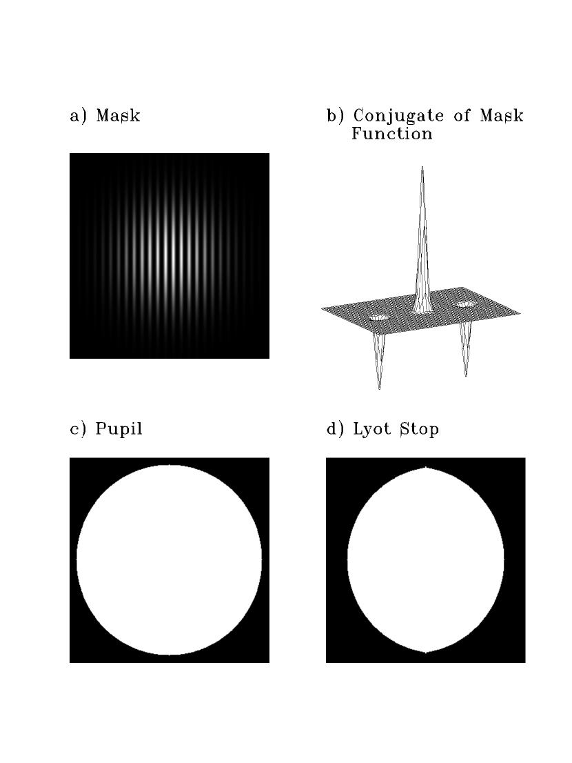
Figure 2 illustrates the action of a one-dimensional coronagraph with a band-limited mask. Figure 2a shows the same entrance pupil as in Figure 1a, a tophat aperture. Again, we will consider an on-axis incoming wave, .

We chose for this illustration the band-limited mask ATF
| (7) |
where N is a constant of normalization chosen to keep . The ITF of this mask is
| (8) |
The conjugate of this mask ATF is
| (9) |
as shown in Figure 2b. This function is zero everywhere but where .
The second pupil field, shown in Figure 2c, is now identically zero except for within a small region around the edges of the aperture, provided that the mask that is completely opaque on-axis. A simple Lyot stop (Figure 2d) combined with a band-limited mask can eliminate all of the light from an on-axis source. The result is that the final field from an on-axis source (Figure 2e) is identically zero.
For a band-limited mask that operates on the intensity of the first image, the mask ATF, , may be any band-limited function of with , and . There are uncountably many such functions. Figure 3 shows some examples of one-dimensional band-limited functions that meet these criteria. All of the functions shown have the same bandwidth, . The ordinate in this figure is distance from the optical axis in the image plane, measured in units of . Figure 3a shows mask ATFs, and Figure 3b shows the corresponding transmissivities. The range of functions in this Figure illustrates a fundamental tradeoff; masks with small cores have large sidelobes, and vise versa.

The functions shown in Figure 3 should be viewed only as building blocks for constructing band-limited masks. Any linear combination of band-limited functions is a band-limited function. Any product of band-limited functions is a band-limited function, though since multiplying functions corresponds to convolving their transforms, the product of two mask ATFs will generally have greater bandwidth than either original function. More options appear in two dimensions. For example, the mask ATF of a two-dimensional band-limited mask might be a product of one band-limited function of with another band-limited function of , like , where and are the bandwidths in the and (or and ) directions. It is possible to design masks by combining simple band-limited functions that are free of sidelobes in specified regions of the image plane.
Naturally, constructing a band-limited mask requires a mask of infinite extent. In reality, the physical size of the mask will be limited to a few thousand diffraction widths. The result will be that will be convolved by a sinc function, or possibly some other taper, so a small amount of on-axis light will leak through the coronagraph.
However, this limitation is not likely to be important. For example, consider a one-dimensional coronagraph whose mask ATF is tapered by a Gaussian with , so that the mask becomes opaque at the edges. The tapering effectively convolves with . The convolution of this function with a tophat aperture falls off as near the aperture edges (see Equation 5). For a Lyot stop designed to block light within of the edges of the entrance pupil, we find that the field at the edge of the Lyot stop has been reduced by a factor of . This corresponds to a reduction in transmitted power by a factor of better than , a small quantity if ever there were one.
5 THE INTENSITY MASK, A NULLING INTERFEROMETER ANALOG
A particularly simple example of a band-limited mask has a mask ATF
| (10) |
and ITF . The conjugate of this mask ATF is
| (11) |
where is the unit vector along the axis. Figure 4 illustrates a tapered version of this mask. Figure 4a shows the mask opacity, , where
| (12) |
and Figure 4b shows the conjugate of the mask ATF,
| (13) |
The diffraction limit of a 10 m aperture at 0.5 m is 10 mas. A TPF design should be capable of finding planets as close as 30 mas from the star, an angular separation corresponding to a transverse distance of 0.3 AU at 10 pc. With this design, we can search as close as 30 mas from a star using a 10 m telescope at m by choosing , so the half-power point in the mask ITF is at . From the prescription in Section 4 for a one-dimensional coronagraph, we know that an appropriate Lyot stop would be one that blocks the region within roughly of the pupil edge. This prescription applies in the and directions independently. Since the bandwidth of this intensity mask is nearly zero in the direction, (Figure 4b), we can make the Lyot stop for this circular aperture correspondingly wider in that direction, so the Lyot stop only blocks of the collecting area (Figure 4d).
This mask has the smallest core of any band-limited mask, and the price for this small core is that the sidelobes are more than 50% opaque over 64% of the image plane. But this blockage need not be a setback. Detecting a planet using a circular coronagraph with a Gaussian mask will require rotating the telescope to distinguish the image of a planet from artifacts produced by aberrations in the optics; the artifacts will rotate with the telescope, but the planet will not. For a coronagraph with a band-limited mask, the same rotation will provide access to any discovery space blocked by the mask. Moreover, rotating the mask independently of the rest of the optics to modulate the transmitted light from the planet may provide a further handle for distinguishing the image of a planet from an optical aberration.
The intensity coronagraph is closely related to a nulling interferometer. The transfer function of an interferometer can be written , where is the aperture function for a single aperture, and is a sum of delta functions that represents the placement of the individual dishes. If the dishes are centered at positions projected onto the plane of the sky, then , where are weights applied to manipulate the fringe pattern. For example, a conventional single-baseline interferometer may have , so . But for a single-baseline nulling interferometer, the beams are combined out of phase, so . The nulling interferometer described in appendix 1 of the TPF booklet (Beichman et al., 1999) has four dishes, weighted by . The output signal from an imaging interferometer has intensity
| (14) |
A Michelson interferometer generally couples only to the zero frequency component of this signal, . By comparison, we saw in Section 2 that a coronagraph forms an image
| (15) |
If we set , the expressions for the detected intensities become identical in form, where , the conjugate of the mask ATF, plays the same role as , the placement and weighting of the interferometer dishes.
Figure 5 illustrates the convolution of the conjugate of the ATF, , for the intensity mask (Equation 11) with the aperture function, , for a circular aperture. The convolution effectively synthesizes three apertures—interferometer dishes—with weights of , , and , spaced by wavelengths. In Figure 5, circles indicate the three apertures, and the grey areas indicate the regions illuminated by an on-axis source.
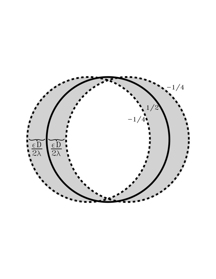
In an interferometer, the telescope apertures do not overlap. But in the coronagraph, the virtual apertures do overlap, and only in the region where all three apertures overlap does the field in the second pupil plane cancel to zero. This region of overlap sets the shape of the Lyot mask shown in Figure 4d. Since any occulting mask ATF with even symmetry can be envisioned as a weighted sum of mask ATFs, we conclude that all intensity masks suffer from this imperfect overlap of virtual pupils, forcing coronagraphs with intensity masks to discard photons in the second pupil plane to achieve high dynamic range.
Figure 5 also demonstrates why a band-limited mask does not work well with an apodized entrance aperture. A coronagraph effectively performs a weighted sum of shifted copies of the entrance aperture with the weights chosen so one copy cancels other copies where they overlap. If the aperture does not have uniform transmissivity, it can not generally uniformly cancel a shifted copy of itself (but note that when the mask has zero bandwidth in one direction, the aperture need not be uniform in that direction).
6 ERRORS THAT CAN REDUCE A CORONAGRAPH’S DYNAMIC RANGE
Generally, TPF designs aim to create a search area where half of the photons from an on-axis source cancel the other half of the photons from an on-axis source, leaving signals from off-axis sources in the search area to fall on a detector relatively un-attenuated. An interferometer performs this cancellation by interfering two beams. A coronagraph performs the same cancellation using diffraction. Consequently, a coronagraph may not circumvent the requirements of accurate control over the phase and amplitude of the wavefront that nulling interferometer designs manifest. Here we consider some of the noise sources that can spoil a coronagraph’s perfect cancellation of light from an on-axis source. These errors can reduce the dynamic range of any coronagraph—with or without a band-limited mask.
6.1 Off-Axis Light
Before we proceed with our discussion of errors, let us consider how a mask treats a point source, like a terrestrial planet, at a small angle from the optical axis. The corresponding incoming electric field is , where the phase is . In other words, the virtual pupils created by the mask are now associated with phase gradients.
A phase gradient in the direction does not affect the the weighted sum of the virtual pupils, as one might expect based on the translational symmetry of the mask. However, gradients in the direction will cause the right virtual pupil in Figure 5 to lag begin the central pupil by , and the left pupil to lead the central pupil by the same phase difference, . Totalling the three phasors shows us that a uniform field of will remain throughout the second pupil plane interior to the Lyot stop. The final image plane will have an image of the point source, with power suppressed by a factor of compared to the image an on-axis source would have in the absence of the image mask. In fact, the point source response for an ideal coronagraph with any band-limited mask and properly chosen Lyot stop takes the form of the mask ITF times the point-spread function created by the Lyot stop.
Recall that a Lyot stop reduces the signal from a planet as well as the signal from an on-axis star. It reduces the effective collecting area, and spreads the planet’s light over a larger image plane area. We shall say that the coronagraph reduces the effective collecting area by a factor , and the peak brightness of the image of a point source by . For a coronagraph with a Gaussian image mask with dynamic range of at , in the the search area. For a comparable coronagraph with a band-limited mask whose half power point is at , .
6.2 Pointing Errors and The Finite Size of the Star
A side effect of having off-axis light leak through the coronagraph is that some starlight will leak through the mask due to a star’s finite size and any error in centering the star on the optical axis. We can compute this leak by treating the stellar disk as a sum of off-axis point sources. Assume the star is a small disk with angular diameter and uniform surface brightness , where is the total flux from the star. Using the approximation , we find that the fractional leak is
| (16) |
where is the angular displacement of the center of the star from the optical axis in the direction, the pointing error. For example, the Sun at a distance of 10 pc would have milliarcseconds. For a coronagraph with m, m, with no pointing error, the fraction of the starlight that will leak through the mask to form an image near the optical axis will be . With a pointing error of 0.5 milliarcseconds along the -axis, the fractional leak increases to . The wings of the resulting extraneous image of the star will contaminate the search area; for instance a stellar leak due to pointing error at the level of may reduce the dynamic range of the coronagraph to in the search area. Band-limited masks with much less sensitivity to pointing errors and the finite size of the star can be designed with the cost of decreased throughput. One approach to pointing a (or , etc.) coronagraph that can also serve to distinguish stellar artifacts from planets is to continually scan the mask across the star to modulate the ratio between the transmitted starlight and the light from any companion.
6.3 Intensity Errors in the Primary Mirror
Suppose that a pupil of characteristic diameter and real amplitude reflectivity factor with even symmetry is covered with patches of diameter , so the ATF of the pupil is wrong by a real amount . The corresponding ITF is
| (17) |
We can use this model to describe errors in the primary mirror reflectivity, or errors in the apodizing function for an apodized pupil.
The image of a point source formed by this pupil has intensity
| (18) |
The quantity is an image of the bad patches on the pupil, a function which has characteristic radius diffraction widths, and area squared diffraction widths. This image is less intense than the image of the whole pupil by a factor of , because the light is spread out into a larger area than the image of the whole pupil. The most potentially dangerous errors are those which concentrate their images in the search area, which is diffraction widths from the optical axis. Let us focus on errors of this size scale, . For these errors, or .
If the pupil is a conventional circular aperture, in the search area. In this case, the term dominates the error budget. Since the Lyot stop reduces the area of the pupil that contributes to the halo by a factor f, we require that , or . If the pupil is a specially shaped or apodized aperture, may be as low as . In this case, the quadratic term and the cross term are roughly equal when the dynamic range is , and the requirement becomes .
With these constraints on , we can now ask, how big a can we tolerate? If the pupil is not apodized, the cross term in Equation 17 dominates everywhere on the pupil, and . Then we require for a circular aperture, and for an aperture such as the one suggested by Spergel (2001). If the pupil is apodized, then over the transmissive zones of the pupil, the cross term dominates. In the wings of the apodization function, where , the quadratic term in Equation 17 may become important. These dark regions may be shaded less accurately than the rest of the surface.
6.4 Wavefront Phase Errors
If the primary mirror is not perfectly smooth it will deform the reflected wavefront from an ideal shape. Small perturbations will create a halo of scattered light, which image masks and Lyot stops can not correct, surrounding the image of a point source. This halo of speckles must be fainter than the core of the image by a factor of so the halo around a stellar image won’t swamp the signal from a terrestrial planet. Suppose that the primary is actively corrected by a two-dimensional array of pistons with pistons across the diameter. Let us assume for simplicity a circular aperture and no mask or Lyot stop (so ) and ask how accurate the corrected wavefront must be.
The distance between pistons in our array is . This array of pistons can nominally correct errors in the wavefront reflected from the primary at spatial scales in the pupil plane larger than (assuming 2 pistons to correct sine errors plus 2 pistons to correct cosine errors). Smaller scale errors will remain uncorrected.
Consequently, the active correction can reduce the intensity of the scattered-light halo around a stellar image in the focal plane out to diameter . We must choose to be large enough so that the active optics can eliminate the scattered light over the entire search area. Because we are concerned only with scattering diameters less than , we will estimate the required maximum r.m.s. wavefront error over only those scale sizes between and , and ignore higher-frequency errors.
The Strehl ratio, , of the image of a point source is the ratio of the image’s actual central intensity to the central intensity the image would have if the wavefront were perfect. Since we are ignoring high frequency errors which throw light into angles beyond , we can say that the halo contains a fraction of the stellar photons. Let us denote the nominal diameter of the core image as . Then the brightness of the core of the image of a point source is . Likewise, if the halo is roughly uniform, its brightness out to diameter will be .
The Strehl ratio, , can be approximated by , where , and is the r.m.s. wavefront error. The ratio of r.m.s. brightness in the halo to brightness in the core is then
| (19) |
To detect a terrestrial planet, this ratio must be . In other words, we require . For example, if m and , the pistons must control the wavefront to an r.m.s. accuracy of Å.
An active optics system often relies on the imaged starlight to deduce the required corrections, so the available starlight may limit the rate at which the corrections can be calculated. This condition makes achieving the tolerance mentioned above even more daunting. Achieving the required wavefront accuracy is a major hurdle for coronagraph design (Malbet et al., 1995).
6.5 Errors in the Image Mask Opacity
In the nulling interferometer, a beam-combiner creates a nulling fringe, while in a coronagraph with an occulting mask, the “fringe” is painted on an optical surface. This painted fringe must be fabricated precisely just as the analogous interference fringe must be controlled precisely. This condition applies to both infinite-bandwidth masks and finite-bandwidth masks. For example, if an occulting mask is not completely opaque in the center, but is has an ITF there of , on-axis light will leak through the Lyot stop at an intensity level of on-axis, and an intensity level of a few a few diffraction widths away, sufficient to scuttle a terrestrial planet search. Because the light from the central star is concentrated on a small part of the mask, only that small part of the mask must be built to high precision, but the required precision is high indeed.
Let us consider a more general perturbation to the mask ATF, . The field from an on axis source in the first image plane is , so the field transmitted by the mask is , and the mask ITF is
| (20) |
We will proceed by expressing as a Fourier series. Since the mask ATF for an intensity mask must be real, it is best to work in terms of the sine and cosine basis functions, and write the perturbation as
| (21) | ||||||
With Figure 5 in mind, we recognize that the D.C. term, , creates a single virtual pupil centered on the optical axis, and each sine and cosine term creates a pair of virtual pupils on either side of the optical axis. By analogy with the mask, we can write the spacing between the two virtual pupils created by a given term as , where or for the basis functions in Equation 21. In the case of the sine terms, the fields from the virtual pupils cancel where the pupils overlap. In the case of the cosine terms, the fields from the virtual pupils do not cancel themselves, but the D.C. term cancels them where they overlap, provided the mask is precisely 100% opaque in the center, as in the intensity mask.
The perturbation wavenumbers fall into three interesting regimes, shown in Figure 6. For wavenumbers lower than the mask bandwidth, , or rather, the bandwidth blocked by the Lyot stop, , in the appropriate direction, the virtual pupils overlap throughout most of the region where the matched Lyot stop transmits. In this first regime (Figure 6a), the Lyot stop suppresses the effect of a sine perturbation. The Lyot stop can suppress a cosine perturbation too, provided that is comes with a matched D.C. term. When , however, the Lyot stop can not suppress the leak due to the perturbation. The situation is at its worst when the virtual pupils cease to overlap with each other at . This regime (Figure 6b) corresponds to perturbations on the size scale of the diffraction limit. When , the virtual pupils are so widely separated that they cease to overlap even with the Lyot aperture. In this third regime (Figure 6c), perturbations have no effect at all.

This analysis shows that the two potentially dangerous kinds of errors are 1) the D.C. term, i.e., making the mask identically opaque in the center, and 2) errors with size scales comparable to the diffraction limit of the primary aperture. For instance, there is no need to be concerned about errors in the mask ATF caused by the finite number of molecules available for a mask coating. However, even in the case of a mask which is perfectly opaque in its center, an extraneous ripple in the mask opacity on the scale of will add speckles to the image of an on-axis point source in a halo whose radius is . Of course, these speckles should be relatively easy to isolate; if the mask is rotated with respect to the telescope, the speckles will rotate with the mask.
Now that we have decided that perturbations on size scales are the most dangerous, consider a mask with intensity transmission factor , where is noise with size scale . A single mode in corresponds to perturbation in the mask intensity transmission factor , a function which is a little bit more complicated than a plain cosine or sine function but still has most of its power on the the same size scale, if . How big a can we tolerate?
Consider a patch of a mask with size . The flux that reaches the patch from an on-axis source with is . A fraction of this light is diffracted into a halo with effective area in the final image. This halo is the image of the region of overlap of some virtual pupils and the Lyot stop; it may have wings or spokes that are just as bright as its center. The result is a noise background with an intensity in the search area. We require that this noise background be less than . In other words, if the patch is near the center of the mask, where it is well-illuminated, the patch must have . Elsewhere, in the wings of the mask, where there is little illumination, the tolerance can be much less severe.
6.6 The Benefits of an Apodized Lyot Stop
The best way to handle pointing errors, the finite angular size of the star, and errors in the image mask opacity may be to use an apodized Lyot stop. Leak due to pointing errors, the finite angular size of a star, and a low-frequency errors in the image mask result in extraneous images of the star appearing near the center of the final image plane. Only the wings of these extraneous images interfere with planet detection. The leak due to these errors can be reduced by a factor of or more by combining a mask with a Lyot stop designed to suppress the wings of the system’s point spread function (PSF). For example, the Lyot stop could be gently apodized with a Hanning window or some other graded function. An apodized Lyot stop can also limit the consequences of higher-frequency errors in the image mask, since these errors produce virtual pupils that overlap the Lyot stop only at the edges of the pupil plane, regions that are dark and graded in an apodized Lyot stop.
Most of the on-axis light has been removed by the image mask before it can reach the Lyot stop, so the construction tolerances for this optic are much less severe than the tolerances computed in Section 6.3. Naturally, the Lyot stop still must be completely opaque over the bandwidth of the light diffracted by the image mask. The cost for using such a specialized Lyot stop will be reduced throughput.
7 CONCLUSION
We showed an example of a coronagraph design using a mask with ITF that is analogous to a nulling imaging interferometer with overlapped entrance pupils. Any coronagraphic occulting mask with even symmetry can be decomposed into a weighted sum of these primitive masks. If the sum is band-limited, with a reasonably small bandwidth, a matched Lyot stop can be designed to block identically all of the light from an on-axis source while discarding a minimal fraction of the light from an off-axis source. The Lyot stop matched to the ITF mask may use as much as of the collecting area of a 10-meter circular telescope to search for planets 30 mas from nearby stars. Planets imaged through such a large-aperture Lyot stop benefit from a large fraction of the collecting area and angular resolution of the primary mirror. Other band-limited masks may be designed with much smaller sidelobes at the price of a narrower Lyot stop.
Imaging extrasolar terrestrial planets with a coronagraph requires very precise optics. We pessimistically restricted our error analysis to the case where all the power in the errors is at the most dangerous size scales, where errors scatter light into a halo with radius roughly a few . In this case, we require a beam from the primary mirror with r.m.s. pathlength error of Å and intensity errors of . We also require an image mask with low-frequency intensity transmission factor errors within a few diffraction widths of the optical axis. An apodized pupil can be combined with in image mask to lighten the error tolerances on both the image mask opacity and the apodizing mask opacity if the apodized pupil is placed in the second pupil plane as an apodized Lyot stop. Building a telescope that meets these tolerances may require substantial new developments in optical technology. However, before we can build such precision optics, we can adapt the techniques described here for lower dynamic-range applications on existing telescopes—perhaps to image extrasolar giant plants.
References
- Beichman et al. (1999) Beichman, C. A., Woolf, N. J., & Lindensmith, C. A. eds. 1999, The Terrestrial Planet Finder (Pasadena: JPL Publication 99-3)
- Fridlund (2000) Fridlund, M. ed. 2000, DARWIN, The InfraRed Space Interferometer, The search for Terrestrial Exoplanets and High Resolution Imaging of the Universe (ESA-SCI(2000)12)
- Guyon et al. (1999) Guyon, O., Roddier, C., Graves, J. E.; Roddier, F., Cuevas, S., Espejo, C., Gonzalez, S., Martinez, A., Bisiacchi, G., Vuntesmeri, V. 1999, PASP, 111, 1321
- Des Marais et al. (2002) Des Marais, D. J., Harwit, M., Jucks, K., Kasting, J., Lunine, J., Lin, D., Seager, S., Schneider, J., Traub, W. A., & Woolf, N. 2002, submitted to Astrobiology.
- Kasdin et al. (2001) Kasdin, J. N., Spergel, D. N. & Littman, M. G. 2001, submitted to Applied Optics
- Lyot (1939) Lyot, B. 1939, MNRAS, 99, 580
- Malbet (1996) Malbet, F. 1996, A&A, 115, 161
- Malbet et al. (1995) Malbet, F., Yu, W., & Shao, M. 1995, PASP, 107, 386
- Marcy et al. (2001) Marcy, G. et al. 2001, http://exoplanets.org/
- Nisenson & Papaliolios (2001) Nisenson, P., & Papaliolios, C. 2001, ApJ, 548, L201
- Noll (1976) Noll, R. J. 1976, J. Opt. Soc. Am., 63, 1399
- Sivaramakrishnan et al. (2001) Sivaramakrishnan, A., Koresko, C. D., Makidon, R. B., Berkefeld, T., & Kuchner, M. J. 2001, ApJ, 552, 397
- Spergel (2001) Spergel, D. N. 2001, astro-ph/0101142
- Schneider (2001) Schneider, J. 2001, The Extra-solar Planets Encyclopedia, http://www.obspm.fr/planets
- Traub & Jucks (2001) Traub, W. A., Jucks, K. 2001, to appear in AGU Geophysical Monograph Series, spring 2002, Comparative Aeronomy in the Solar System, ed. M. Mendilo, A. Nagy, & H. Waite (AGU)
- Wang & Vaughan (1988) Wang, T. & Vaughan, A. H. 1988, Appl. Opt., 27, 27