In.XS: project for a future spaceborne hard X-ray all-sky survey
Abstract
The latest all-sky survey in hard X-ray band was performed by the HEAO-1 satellite () with an angular resolution of [13]. A diffuse hard X-Ray background (HXB) was detected between and [16]. The main scientific goal of In.XS is to resolve a large fraction of this HXB into individual sources.
As no distortion by Compton up-scattering is seen in the spectrum of the microwave background[17], the hard X-ray background is believed to be mainly due to point sources. “Type I” Active Galactic Nuclei (AGN) have softer X-ray spectra than the hard X-ray background, so other sources must be considered, like faint “Type II” or “absorbed” AGN. These could be distinguished through hard X-ray spectroscopic or hardness ratio observations.
Here we present In.XS - a mission concept designed to conduct the first imaging all-sky hard X-ray ()survey. The angular resolution of nearly and good sensitivity at high energies is provided by the latest multilayer focussing mirrors, with semiconductor-based (GaAs) arrays of detectors. We also describe the mission operations, and how the all-sky survey will be complemented by follow-up pointed observations of selected fields. The good angular resolution will allow correlations and identification with objects seen at other wavelengths. In addition, since a large fraction of the Type II AGN luminosity is emitted in the hard X-ray band, this survey will provide a large unbiased sample of the AGN population. This may provide constraints on AGN evolution through the possible observation of a turnover in deep field source statistics.
Keywords: Satellite, Hard X-Ray Background, AGN, GaAs, Multilayers…
1 INTRODUCTION
Since the first (1964) observational proof of the existence of a cosmological radiation backround (CRB) in radiowaves[20], the question has been raised of its extension along the electromagnetic spectrum and its origin.
If the radiowave background, as well as its extension into microwaves later (1990) observed by the COBE satellite, is now widely admitted to originate around the time of recombination (z=1000), other diffuse emissions have been detected at different wavelengths and their origins still remain hypothetical. A strong background has indeed been discovered in the far-infrared data from COBE[22]. The energy contained between wavelengths and is about twice the energy contained in the ultraviolet-visible part of the spectrum[7] and is by far the most dominant component of the CRB after the microwave background itself.
1.1 The X-ray Background (XRB)
In 1967, isotropic X-ray emission was evidenced after rocket experiments in the band with a somewhat powerlaw-like spectrum[24] and was hence primarily thought to be due to inverse Compton scattering of microwave photons on electrons in a hot intergalactic medium[2]. But as no strong distortion by Compton up-scattering is seen in the spectrum of the microwave background[17], this scenario shall be disregarded.
While of the soft XRB () has been since resolved into individual sources[9] by ROSAT, as well as of the mid XRB () by the Chandra satellite[18], this is not true for the hard X-ray component () of the background.
Apart from invoking exotic models there are two main sources of radiation in the universe in the period following recombination during which structures form: gravitational energy of contracting or accreting objects and nucleosynthesis in stars of H and He into heavier elements. In the first case, only Black Holes can radiate a substantial fraction of their rest mass during formation or accretion processes[26]. In the second case, starburst in galaxies can radiate five times as much energy as galactic black holes[12].
1.2 Active Galactic Nuclei (AGN)
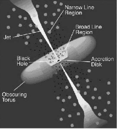
Individual sources powering softer components of the XRB were demonstrated to be mainly Seyfert galaxies[23], not surprisingly of that kind presenting a strong evidence for an accreting supermassive black hole at their center. In the framework of the AGN unified scheme (Fig. 1), these galaxies are refered to as “Type 1 AGN”. The problem is that their spectra do not account for the bump in the harder XRB components, so that other sources must be considered[14].
Nevertheless, a large () fraction of the hard X-ray background (XRB) spectral intensity could be well reproduced by the combined emission of unobscured (type 1) and obscured (type 2) Seyfert galaxies and quasars with a distribution of absorption column densities and luminosities[4]. The key ingredient of this model is the presence of obscured AGN whose emission in the traditional band is blocked by the dust torus but allows to fit the bump around .
It is likely that the energy density of the absorbed AGN which would peak in the soft X-rays is reradiated in the far-infrared and assuming that the peak of the XRB provides an unobscured estimate of the integrated AGN energy density, the obscured AGN responsible for the hard XRB could account for no less than of the far-infrared background[5] and as much as [15]. On the other hand, it is shown on the basis of spectroscopy (carried out with ISO) of luminous and ultraluminous IR galaxies, that the fraction of the energy coming from the central AGN is in general smaller than the fraction coming from starburst activity but increasing with luminosity[6].
The far-infrared and the hard X-ray bands should hence be the best two regions of the spectrum to select AGN in a manner insensitive to their level of obscuration.
2 In.XS MISSION CONCEPT
The latest all-sky survey in hard X-ray band was done by the HEAO-1 satellite. Its A-2 instrument detected 72 point sources[13] to the limit of in the band with an angular resolution of . A diffuse hard X-ray background[16] of at was also detected.
In addition, there is currently an ongoing effort to re-analyse BATSE data with a novel analysis technique and perform a sensitive all sky survey in the range. The 3 sigma flux sensitivity for a survey performed using 50 days of continuous data is with an angular resolution of [25].
The main scientific goal of the International X-ray Surveyor (In.XS) is to resolve a large fraction of this diffuse hard X-ray background into individual sources, mainly AGN hidden in other wavelength bands. A comparison between the high performance of In.XS with that of other missions is made in Tab. 1.
| Mission/Instrument | FOV | Resolution | Energy range | Sensitivity |
|---|---|---|---|---|
| (* not yet launched) | (degrees) | (arcmin) | (keV) | (mCrab) (*not all-sky survey) |
| In.XS * | ||||
| HEAO-1 A-2 | ||||
| Granat ART-P | * (in 8 hours) | |||
| BATSE | ||||
| ROSAT | ||||
| XMM-Newton or Chandra | ||||
| INTEGRAL JEM-X * (2002) | * (in 15 min) | |||
| SWIFT * (2003) | ||||
| ISS EXIST * (2007) | ||||
| SRG MARTLIME * | * (in 24 hours) | |||
| CHIP * | (in 1 hour) |
2.1 Scientific Goals
With a detection limit of in the band, approximately 20000 new sources are expected, most of them AGN. This source count estimate is derived from a relation with slope, consistent with HEAO-1[21] and ASCA[27] observations. A fraction of of the new sources would be galactic, most of them accreting X-ray pulsars. Crude variability estimates would be obtained, as the satellite will scan the sky twice, with six months between 2 exposures of each (cf. Sec. 4.1.).
The planned angular resolution of nearly allows for correlation with other deep X-ray surveys[9] or infrared background surveys[22], for easier identification of counterparts in other wavelengths and provides a limited level of sources confusion.
The observed hardness ratios of sources would allow crude division between AGN type 1 and type 2. The ratio of AGN I to AGN II would hence allow estimates of the average dust torus size and AGN I/II ratio versus redshift would give some constraints on dust torus evolution. As a large fraction of the AGN luminosity is emitted in the hard X-ray band, and only a few small classes of other sources are seen in this band, a good population synthesis of AGN would be easiest to obtain from a large sample of AGN observed in hard X-rays.
2.2 Secondary Goals
The main result of the first mission phase, the all-sky survey, will be a large source catalogue. In the second phase of the mission pointed observations will be conducted, whereby interesting targets could be selected from the source catalogue compiled during the first phase. This can also include raster scans of selected regions and deep field observations of a few very interesting regions (e.g. Galactic Centre and Lockman Hole). The deeper observations are needed to calibrate the hardness ratio - AGN type relation by obtaining a sufficient sample of AGN with known types and better spectra, and should lead to about in the range with a detection limit of in .
The AGN evolution models would be constrained if the turnover of the relation is seen in the deep field observations. Since the sources of the all-sky catalog contribute to roughly half of the diffuse X-ray background, there is a good chance to reach the turnover point in the deep field observations.
Furthermore, in addition to the test of the unified model of AGN provided by the correlation between X-rays and existing IR surveys (ISO FIRBACK and ELAIS), the combination of infrared probes of dust conditions (to be conducted in the forthcoming years with SIRTF and FIRST-Herschell), together with radio and hard X-ray data probing supernovae and X-ray binaries activity, should lead to major constraints on starburst evolution models in galaxies. Also, having both IR and X-ray photometry for these objects should enable a detailed study of how X-ray photons are reprocessed by the dust torus, and facilitate the estimation of the intrinsic spectrum of these X-rays.
Finally, this all-sky survey should be compared with its submillimeter counterpart to be realized by the Planck satellite by the end of the decade and which should provide us with maps of the Sunyaev-Zel’dovich (SZ) effect, Compton recoil of the CRB photons on the hot electronic gas of clusters of galaxies (ClG), and deep ClG catalogs. This comparison could put further constraints on the possible diffuse component of the XRB and possibly maps of the Hubble parameter , since the SZ effect is not dependant on the redshift of the source object.
3 In.XS INSTRUMENT PAYLOAD
The scientific goals, as outlined in previous section, define the scientific mission requirements to be achieved as listed in Tab. 2.
| FOV | Resolution | Energy range | Sensitivity | Energy Resolution |
|---|---|---|---|---|
| (deg) | (arcmin) | (keV) | (mCrab) | (keV) |
| at | ||||
| (to allow scanning | (to allow | (to explore | (to allow unbiased | (to discriminate |
| all-sky in 6 | correlations and | absorbed regions | sampling of AGN | between AGN |
| months from LEO) | cross-identifications) | of X-ray spectrum) | population) | types spectra) |
3.1 X-ray Telescopes
Since 1978, grazing incidence mirrors using Bragg theory have been the working horse of X-ray astronomy, but these mirrors were limited in energy range. In 1993, this limitation was alleviated from about up to , but at the cost of spatial resolution for a (from for HEAO-2 down to for ASCA), since the Bragg condition roughly implies , where is the critical incidence angle, half the FOV, the considered energy and the energy resolution. These grazing mirrors, coated with atomic monolayers (to improve reflectivity) and designed as a combination of paraboloid and hyperboloid surfaces (instead of simple conical surfaces) to improve spatial resolution (XMM-Newton now reaches about spatial resolution) and reduce chromatic aberrations, are still in use in modern X-ray space observatories.
But it has been demonstrated that a multilayer coating enhances the reflectivity beyond the critical angle[28], up to , since the photoelectric absorbtion is less effective in the multilayer structure, so that the Bragg condition still is satisfied over the broad band. Alternance of Pt/C layers is hence proved to be the best combination, in addition to Pt monolayer overcoating.
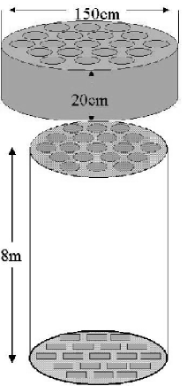
In order to meet the sensitivity requirements, an effective area of at is needed. This will be achieved for a focal length by mirror units, each made of about 100 multi-nested multilayers ( Pt/C layer pairs) shells (Fig. 2). Each unit has a diameter of and a length of .
Finally, applying the former Bragg relation to our science requirements, we find that it should be difficult to achieve more than FOV without reducing performance. However, it is reported that with a higher (9th) polynomial degree in the “Wolter I” approximation of the mirror shape, wider FOV could be reached[3].
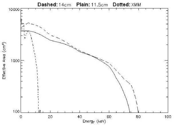
(RIGHT) Plot of the In.XS 19 telescopes total effective area for 2 different radii of each modules, compared to that of the XMM-Newton 3 telescopes.
This assembly constitutes a major improvement as compared to what is planned for InFOCS and Constellation-X designs.
3.2 X-ray Solid State Detectors
In a survey of the available detector technologies (cf. Tab. 3), GaAs compound semiconductors were found to fit our science requirements best.
| Type | Missions | Energy range (keV) | Comments |
|---|---|---|---|
| GaAs array | In.XS | pixel size , | |
| , | |||
| extremely uniform response | |||
| CdZnTe array | InFOCS, CHIP, | pixel size , | |
| Constellation-X | , | ||
| discrepancies from pixel to pixel | |||
| TlBr array | |||
| Si(Li) diode | |||
| Si CCD | ASCA, XMM, AXAF | ||
| Gas Prop. Coun. | MARTLIME, ROSAT | depends on gas | big pixels … |
| Calorimeter | rockets | ||
| Bolometer | must be cooled … | ||
| Diamond |
GaAs arrays work perfectly in our required energy range. They provide a sufficient spectral resolution ( to ) already at room temperature, which prevents usage of costly onboard cryogenics (at low earth orbits, spacecraft has to endure substantial thermal variations). An improved energy resolution (by a factor of 2) can be achieved with simple passive cooling down to [1].
The best absorption layer thickness should be around for pixels size comprised between and and a resulting quantum efficiency of to in our energy range[19].
It is reported (Metorex Inc., http://www.metorex.fi, June 2000) that industrial GaAS arrays of pixels are now available, which is enough to sample our FOV at spatial resolution consistent with mirror PSF (). Given the telescope characteristics, a detector array of is needed to fit the focal plane of one unit. However, GaAs wafers yet come no larger than . Therefore, square arrays of each should be considered to provide a total of pixels behind each telescope unit. The needed pixel size would then be around , corresponding to on the sky (Shannon sampling of the PSF).
3.3 Readout Electronics
GaAs detectors can be equipped by individual wire bonding (4096 wires per detector unit in our case), thus allowing spectro-imaging by independent energy determination in each pixel of the image. Each pixel is then preamplified (FET) and a global spectro-amplifier feeds a digitizer (thus allowing us to divide our energy range into 4096 channels of )[19]. These are classical space qualified technologies and the electronic noise is no more than , that is just less than our expected cosmic background at .
The readout time cycle of the electronics is of the order of a few microseconds, which prevents smearing of the PSF. The sky scanning rate of the satellite is (cf. Sec. 4.1), equivalent to detector pixels per second. Smearing of the PSF over several pixels is hence avoided with a readout cycle faster than , which is easily fulfilled.
The encoding of data must be considered through an event list (science data) and housekeeping. Each event should be characterized by its position (telescope number: , pixel coordinates ), energy () and timestamp (a typical long integer on ), for a total of . The signal may vary from ( X-ray background flux on our telescopes) up to probably for the brightest objects (one hundred times less than the pile-up limit thanks to individual wiring electronics), for a data rate of to . It seems reasonable to assume an average value of dominated by the standard housekeeping data rate.
3.4 Instrument Calibrations
A first run of ground based calibrations could be undertaken on monochromatic X-ray sources with large housing capability for effective area and vignetting measurements of mirror modules (like the Panter station in Germany); the detectors could be hosted by white synchrotron facilities (like Bessy in Germany or the new SoLEIL in France) for quantum efficiency, flat field and spectral resolution measurements. One should particularly take care of variation of these parameters with temperature, since the superstructure may have to endure significant thermal fluctuations along its low earth orbit (cf. Sec. 4.1) and that may produce strong variations in the mirror performance and between each detector preamplifying chain.
Onboard radioactive sources ( and ) as well as well known astrophysical sources (3C273 Quasar, Crab Nebula, etc.) would provide inflight calibrations. Common targets during the second phase (pointed observations) should also be considered for cross-correlations with other observatories like XMM-Newton or INTEGRAL. A filter wheel in front of each detector with different positions (“open”, “filter”, “closed”) would allow adjusting incident flux towards limited damage flux level. In addition, this would ensure protection of the detectors against radiation damage during strong solar flares.
4 In.XS SPACECRAFT AND OPERATION
4.1 Spacecraft Design and Properties
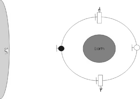
The optimal choice of orbit for our scientific requirements would be a circular low earth orbit (LEO) at an altitude of about . This choice of orbit allows us to keep the background at the lowest possible level, while at the same time avoiding the radiation belts. Furthermore this choice keeps the operational costs of the mission (launch …) within reasonable limits. The inclination of the orbit will be 7 degrees. An equatorial orbit is possible, but is not necessary for our purposes.
By choosing a rotational period of the spacecraft around its transversal axis such that it equals its period of revolution (Fig. 3), we enable the spacecraft to scan the entire sky within 6 months, while at the same time pointing away from the earth at all times. The same result could have been achieved with a polar orbit while constantly pointing away from the earth and the sun, but this would have meaned suffering from polar aurorae radiation.
The proposed minimum duration of the first part of the mission should therefore be no less than 1 year (ideally 1.5 years including Com/Cal/PV Phases) to allow for redundancy, instrument failures and in order to cover those FOV obstructed by the Moon in the first run.
It should be noted that, although our choice of orbital motion does allow the solar panels to be pointing towards the sun at all times, the low altitude of the orbit leads to a significant amount of sky shadowing of approximately , resulting in an eclipsing time of 36 minutes per orbit. Therefore we have to account for batteries and data storage on board the spacecraft.
We estimate the total mass of the spacecraft to be approximately , including for superstructure, for science payload and of monopropellant necessary for altitude corrections and de-orbiting at the end of the mission. Due to the relatively short overall lifetime of the mission (3 to 6 years), further orbit maintenance (i.e. altitude correction of an annual loss of about ) is not vital; this allows us to economize propellant and keep the total mass down.
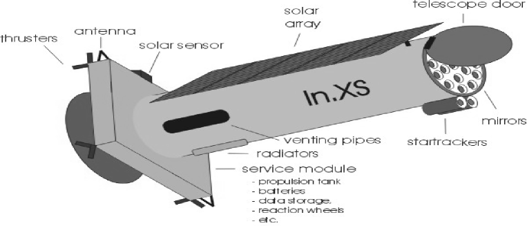
A Ariane IV class (like U.S. Delta II or Japanese H-1 or Russian Cyclone) launcher should be sufficient considering the relatively low overall mass of the mission. However an extra long fairing configuration of the launcher is needed to host the spacecraft, which is approximately long (Fig. 4) due to the required focal length.
We estimate the total energy consumption for the service module (data handling, antennae, etc.) and payload (detectors, etc.) to be . This can be provided by solar arrays with a total effective area of assuming efficiency Si cells and NiCd batteries (able to endure about 5500 charge/discharge cycles per year) for the eclipsing times111This estimate includes 20% overhead..
The science objectives (Tab. 2) require the Absolute Pointing Error (APE) to be less than , and the Relative Pointing Error (RPE) should be kept small compared to the PSF, i.e. of the order of , which is easily achieved with current reaction wheel techniques.
4.2 In.XS Groundsegment
Table 4 summarizes the proposed Mission Profile for the In.XS project. It comprises three parts: the first part is dedicated to the commencement of operation of the satellite and the instruments, the two other parts are dealing with the observations as described in the Mission Concept above.
| Launch and Early Orbit Phase | |
| Commissioning Phase (incl. Outgassing) | 1 month |
| Calibration and Performance Validation Phases | 2 months |
| Whole sky survey | 1.3 years |
| processed data available 3 months after observation | |
| Catalogue of sources (all data public domain) | |
| Pointed follow-up observations of selected objects | 2 years |
| – Observing time divided into guaranteed time (PIs) and open proposals | |
| – Announcement of Opportunity (AO) and Observation Time Allocation Commitee (OTAC) | |
| – Scheduling and Observation execution | |
| – Priority rights and Data distribution (PIs or public archives) |
The Groundsegment of In.XS has the following duties: providing all facilities and services needed for mission operation on ground, providing the data link from spacecraft to the ground, preparing a timeline for the operation, carrying out the monitoring, controlling and commanding of the spacecraft and instruments, executing transmission and the processing and archiving of the data.
The Groundsegment will consist of the following strongly interacting parts:
-
•
Groundstations: the groundstations will be responsible for keeping contact with the satellite and exchange telecommands (TC, controlling) and telemetry (TM, science data and housekeeping), respectively. As we propose a near-equatorial orbit for In.XS, the ESA groundstation in Kourou (French Guyana) is suitable for communication with the satellite, a possible backup station would be the ESA facility in Malindi (Kenya).
-
•
Mission Operations Center (MOC): The MOC will be responsible for all mission-operation related activities (safety checks for spacecraft and instruments, storing TM, routing TM to the SOC, TC commanding). In.XS could make use of the existing facilities of ESA/ESOC in Darmstadt (Germany) as MOC.
-
•
Science Operations Center (SOC): The SOC will be responsible for all science related activities, i.e. instrument calibration, performance monitoring and survey analysis. Besides, it should perform the mission planning, provide the possibility of a quick-look-analysis on the incoming scientific data, archive the data and make it available for the scientific community. The exact number and location(s) of required SOC(s) is left to be decided on and supported by the PI-teams. In return, PIs will publish the all-sky catalogue and get guaranteed time during the pointed observations phase. For data distribution, use of the ESA OPSNET should be considered.
The maximum data flow for scientific and housekeeping data was calculated to be about , which results in 222 per orbit ( daily). To keep the costs low, we decided to use only one telemetry downlink per day. This means, that we have to provide for 24 hours worth of onboard data-storage. To be on the safe side, total onboard memory storage should amount to (almost 2 days, which is very reasonable when compared to the flash-eproms Mo price rate). If one assumes that the satellite will be visible during a window per orbit from the main groundstation and of this time has to be used for telemetry, a minimum transmission rate of ( per window) would be enough by far for the daily downlink. For telecommunication with the satellite a parabolic antenna () at the groundstation and 2 low-gain antennae (, , ) onboard the satellite are required. Calculations show that with this equipment one can reach transmission rates well sufficient to get all the data safely down. The calculated maximum rate for the telecommands (TC) uplink is (like an InMarSat M-4 terminal), providing sufficient margin considering the expected TC rate of . One year of all-sky survey raw data archive should hence require mass storage, i.e. roughly one double-sided DVD.
5 CONCLUSION AND FUTURE DIRECTIONS
Assuming that instruments and SOC are provided by the scientific community, this project suffers from no severe cost drivers, since it only uses standard spacecraft technology, limited groundsegment operations and launcher configuration and requires only limited propellant capacity, thermal and attitude control.
Given its high sensitivity, spatial resolution, spectral resolution, all-sky survey capability in the range, In.XS hence fits a typical high technology - short term profile, suitable for an ESA flexi-mission or a NASA “cheaper - faster - better” concept, which could give important results toward X-ray background studies but also various galactic sources, AGN, clusters of galaxies, etc.
And remember: it is spelled I - n . X - S, but is pronounced “an access” (to the hidden universe) …
ACKNOWLEDGMENTS
The In.XS satellite is a project originating from the Alpbach 2000 summerschool, co-organized by the Austrian and European Space Agencies (ASA, ESA). Our group of students wish to thank again the whole Alpach organizing commitee, in particular Johannes “Dear Friend” Ortner, and all our scientific tutors, R. Much, A. Parmar, M. Turner, and also Bruno Gardini and Kevin Bennet for their precious space missions experience, as well as all the staff of the Hotel Böglerhof. P. Marty ackowledges the financial supports of both the Centre National d’Etudes Spatiales (CNES) and the Ecole Doctorale d’Astronomie-Astrophysique d’Ile de France (Paris University) which allowed the attendance of this school. J. Schultz acknowledges the financial support of the Space Research Programme at University of Helsinki, funded by the Academy of Finland.
Alpbach 2000 summerschool: http://www.asaspace.at/events/alpbach2000rep.html
In.XS project: http://www-station.ias.u-psud.fr/inxs
References
- [1] Bavdaz, M., et al., “Epitaxial GaAs X-ray detectors for X-ray astrophysics,” 1999, Proc. SPIE, 3768, 451.
- [2] Brecher, K., Morrison, P., “Cosmology, black body radiation and the diffuse X-ray background,” 1967, ApJ, 150L, 61B.
- [3] Citterio, O., et al., “X-ray optics for the WFXT telescope,” 1999, Proc. SPIE, 3766, 198C.
- [4] Comastri, A., et al., “The contribution of AGN to X-ray background,” 1995, A&A, 296, 1-12.
- [5] Fabian, A., et al., “Do nuclear starbursts obscure the X-ray background?” 1998, MNRAS, 297L, 11F.
- [6] Genzel, R., et al., “What powers ultraluminous FIRAS galaxies?” 1998, ApJ, 498, 579G.
- [7] Gispert, R., et al., “Implications of the cosmic infrared background for light production and the star formation history in the Universe,” 1999, A&A, 360, 1G.
- [8] Harrison, F., et al., “Technological development for the Constellation-X X-ray telescope,” 1999, Proc. SPIE, 3765, 104H.
- [9] Hasinger, G., et al., “The ROSAT deep survey: I. X-ray sources in the Lockman field,” 1998, A&A, 329, 482-494.
- [10] Hill, J., et al., “The Swift X-ray telescope,” 1999, AAS, 195, 7101H.
- [11] Kraft, S., et al., “Recent results on the factors governing energy resolution in compound semiconductors to be used future spectroscopic detectors for hard X-ray astronomy,” 1998, Proc. SPIE, 3445, 246K.
- [12] Lagache, G., et al., “First detection of the warm ionized medium dust emission. Implication for the cosmic far-infrared background,” 1999, A&A, 344, 322L.
- [13] Levine M., et al., “The HEAO-1 catalogue of high-energy X-ray sources,” 1984, ApJS, 54, 581-617.
- [14] Madau, P., et al., “The unified Seyfert scheme and the origin of the cosmic X-ray background”, 1994, MNRAS, 270, L17-L21.
- [15] Manners, J., et al., “Obscured AGN and the extragalactic background,” 2000, Proc. LSSX, 387M.
- [16] Marshall F.E., et al., “The diffuse X-ray spectrum from 3 to 50 keV,” 1980, ApJ, 235, 4-10.
- [17] Mather J.C., et al., “Measurement of the cosmic microwave background spectrum by the COBE FIRAS instrument,” 1994, ApJ, 420, 439-444.
- [18] Mushotzky, R.F., et al., “Resolving the extragalactic hard X-ray background,” 2000, Nature, 404, 459-464.
- [19] Owens, A., et al., “Hard X-ray spectroscopy using small format GaAS arrays,” 2000, Proc. SPIE, 4141, 55O.
- [20] Penzias, A., Wilson, R., “A measurment of excess antenna temperature at 4080 Mc/s,” 1965, ApJ, 142, 419P.
- [21] Piccinotti G., et al., “A complete X-ray sample of the high-latitude (absolute value of B greater than 20 deg) sky from HEAO-1 A-2 - LogN-logS and luminosity functions,” 1982, ApJ, 253, 485-503.
- [22] Puget, J.-L., et al., “Tentative detection of a cosmic far-infrared background with COBE,” 1996, A&A, 308L, 5P.
- [23] Schmidt, M., et al., “The ROSAT deep survey: II. Optical identification, photometry and spectra of X-ray sources in the Lockman field,” 1998, A&A, 329, 495-503.
- [24] Seward, F., et al., “Diffuse cosmic X-ray background between 4 and 40 keV,” 1967, ApJ, 150, 845S.
- [25] Shaw, S.E., et al., “A hard X-ray all-sky survey using BATSE earth occultation data,” 2000, HEAD, 32, 4419S.
- [26] Silk, J., Rees, M., “Quasars and galaxies formation,” 1998, A&A, 331L, 1S.
- [27] Ueda Y., et al., “LogN-LogS relations and spectral properties of sources from the ASCA large sky survey: their implications for the origin of the cosmic X-ray background,” 1999, ApJ, 518, 656-671.
- [28] Yamashita, K., “Multilayer X-ray optical systems for future X-ray astronomy missions,” 1997, in Next Generation X-ray Observatories, Turner & Watson, eds., Proc. Leicester University X-ray Astronomy Group Special Report 97/02, p.115.