Structure of Magnetocentrifugal Disk-Winds:
From the Launching Surface
to Large Distances
11institutetext: Department of Astronomy and Astrophysics, University of Chicago,
Chicago, IL 60637, USA
22institutetext: Department of Astronomy, University of Virginia, Charlottesville,
VA 22903, USA
33institutetext: Theoretical Astrophysics, Caltech, Pasadena, CA 91125, USA
Structure of Magnetocentrifugal Disk-Winds: From the Launching Surface to Large Distances
Abstract
Protostellar jets and winds are probably driven magnetocentrifugally from the surface of accretion disks close to the central stellar objects. The exact launching conditions on the disk, such as the distributions of magnetic flux and mass ejection rate, are poorly unknown. They could be constrained from observations at large distances, provided that a robust model is available to link the observable properties of the jets and winds at the large distances to the conditions at the base of the flow. We discuss the difficulties in constructing such large-scale wind models, and describe a novel technique which enables us to numerically follow the acceleration and propagation of the wind from the disk surface to arbitrarily large distances and the collimation of part of the wind into a dense, narrow “jet” around the rotation axis. Special attention is paid to the shape of the jet and its mass flux relative to that of the whole wind. The mass flux ratio is a measure of the jet formation efficiency.
1 Basic Mechanism and Previous Work
The magnetocentrifugal mechanism is the leading candidate for producing the jets and winds observed around young stellar objects. The basic principle is relatively simple, and has been understood for a long time ref1 . It envisions parcels of fluid element being lifted off and accelerated centrifugally along rapidly rotating open magnetic field lines anchored firmly on an accretion disk. Beyond a certain point where the energy densities in the bulk flow motion and magnetic field are comparable, the field lines can no longer enforce rigid rotation, and the field becomes increasingly toroidal. It is the “hoop stress” associated with the toroidal field that is thought to be responsible for the wind collimation and jet production. The quantitative properties of the jet expected from this mechanism are poorly determined however, even though the MHD equations that govern the wind structure and jet formation are well known. Our understanding of the jet properties has been hampered to a large extent by the mathematical difficulties associated with obtaining wind solutions.
1.1 Time-Independent Wind Solutions
There are two basic approaches in obtaining wind solutions. The first is to solve for the steady-state wind structure directly from the time-independent MHD equations. These equations can be cast into a second order partial differential equation (the Grad-Shafranov equation). It is well known that, for a cold wind that we are interested in here, the equation changes its type from being elliptic inside the fast (magnetosonic) surface to hyperbolic outside. Computationally, the structure of the inner part of the wind inside the fast surface can be solved first by relaxation, and that beyond the fast surface later by the method of characteristics ref2 ; ref3 . The fact that the position of the fast surface, where the poloidal flow speed matches the fast magnetosonic speed, is unknown a priori poses a problem. To obtain a converged solution, one needs to have a good initial guess of the fast surface position, which is generally difficult to obtain.
1.2 Time-Dependent Numerical Simulations
A more flexible approach is to numerically follow the time evolution of a wind to steady-state, if such a state exists. This approach has been taken by several groups ref4 ; ref5 ; ref6 . It is also the approach that we took ref7 . Our simulations are based on the ZEUS MHD code, and treat the Keplerian disk as a (lower) boundary, on which an open magnetic field of a prescribed distribution is anchored and from which cold material is injected into the wind at a prescribed rate. A novel feature of our simulation is the treatment of the region near the rotation axis, where the magnetocentrifugal mechanism is ineffective. The reason is that to launch a cold parcel of fluid element centrifugally from a Keplerian disk the field line must incline an angle of at least away from the disk normal ref1 . This condition is not met in the axial region since the field line along the axis must be exactly vertical by symmetry. In reality, the axial region may be filled with a normal stellar wind from the central object or bundles of open field lines from the stellar magnetosphere. We are thus motivated to inject a light fluid with little mass flux at a speed fast enough to escape from the potential well along those field lines that fail to operate magnetocentrifugally. The light axial flow provides a plausible inner boundary to the magnetocentrifugal disk-wind, the focus of our investigation.
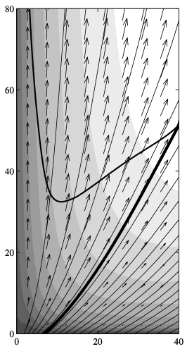
A typical example of the steady-state disk-wind solutions obtained from time-dependent simulations is given in Fig. 1. The wind is driven off all of the (equatorial) disk surface. Flow acceleration is apparent along all field lines except those near the axis where a fast initial injection is imposed. Note that the field (and stream) lines collimate gradually, as expected. What was not expected was the great care that went into designing the shape of the simulation box, so that a steady state could be reached at all. If we were to cut the box shown in Fig. 1 in half or to elongate the box horizontally instead of vertically, and restart the simulation with the same initial and boundary conditions, the wind would become chaotic. The sensitive solution dependence on the simulation box has also been noted by others ref5 . It is a major concern for the time-dependent approach to finding disk-wind solutions.
2 Magnetocentrifugal Winds From Inner Accretion Disks
We believe that the simulation box dependence described above comes from the fact that a large fraction of the wind remains completely sub fast-magnetosonic in the computational domain, as shown in lower-right corner of Fig. 1. Information on the sub-fast outer boundary can propagate upstream all the way to the disk surface and interfere with the wind launching. The reason for the region to remain sub fast is simple: the wind coming off the outer part of the disk encounters the edge of the simulation box too soon; it simply does not have enough room to get accelerated to the fast speed. This situation remains as long as the wind is driven off from all of the (equatorial) disk plane (as assumed in Fig. 1 and other previous time-dependent disk-wind simulations) regardless of the box size. It motivates us to restrict the wind launching to only the inner region of an accretion disk, and focus on inner-disk driven winds for which the simulation box dependence disappears.
2.1 Inner-Disk Driven Winds: Simulation Setup
Physically, the wind launching may be limited to the inner region of a protostellar disk where the temperature is high enough (greater than K) that thermal ionization of alkali metals can provide enough charges to couple the magnetic field to the disk matter. For typical parameters, this occurs inside a radius of order 1 AU. Numerically, we set up the simulation as sketched in Fig. 2. To fill all available space above (and below) the equatorial plane, we demand the last field line anchored at the outer radius of the launching region to lie exactly on the equatorial plane. Wind plasma sliding along this last (horizontal) field line will become super fast-magnetosonic in the computational realm, provided that the size of the simulation box is sufficiently large. Once the whole fast surface is completely enclosed inside the simulation box, the size and shape of the box would have minimal effects on the structure of the wind, especially near the launching surface, since information cannot propagate upstream in a super fast region. In this way, we should be able to study the wind structure up to arbitrarily large distances from the source region, limited only by computer time.

2.2 Large-Scale Wind Structure: Numerical Results
For illustration, we consider a specific example. We adopt as the launching conditions on the disk a power-law distribution of the vertical field strength with radius as and a mass injection rate (per unit area) between 0.1 and 0.8 AU. The inner radius is chosen to mimic the disk truncation radius due to the stellar magnetosphere. Inside this radius, we inject a fast light flow as described earlier. At the edge of the wind launching region, taken to be AU for simplicity, we impose the condition that since the last field (and stream) line must be horizontal. A cubic polynomial is used to connect smoothly the values of (or ) between 0.8 and 1 AU. As before, we follow the time evolution of the wind numerically to a steady state. The steady wind solution, from the launching surface (inside 1 AU) all the way to a large distance of AU, is displayed in Fig. 3 on two scales.
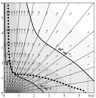
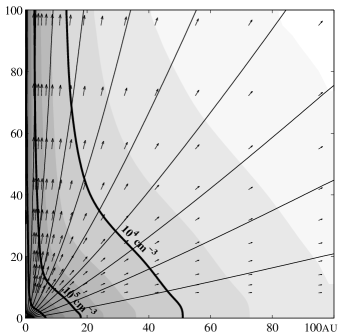
Several features are worth noting. First, the fast surface shown in the smaller box closes on the equatorial plane, as advertised. This closure enabled us to continue the wind solution on to large distances without having to worry about the effects of box size. Second, the wind speed is anisotropic, with a value roughly 3 times higher in the axial region than in the equatorial region. The anisotropy appears to be even stronger in density, which is stratified more or less cylindrically (or jet-like) near the rotation axis, as expected. In the more equatorial region, the density contours bulge outward prominently, retaining some memory of the nearly horizontal shape of the initial density contour. This non-cylindrical shape of density contours is significant because the wind emission in forbidden lines such as [SII]6716,6731 is sensitive to the density ref8 , and the shape of the jet may resemble to a zeroth order the shape of the density contour at some fiducial value. We choose to represent the outer boundary of a “jet” by a fiducial density contour of cm-3 (the outermost contour in the larger box of Fig. 3). The “jet” so defined has a width of AU at a height of AU, comparable to that observed in HH 30 jet. The bulging out at the “jet” base is not observed, however. Furthermore, the “jet” contains only about a quarter of the total wind mass flux, making its formation rather inefficient. These undesirable “jet” features demonstrate that not all combinations of the launching conditions are capable of producing cylindrical jets that contain the majority of the wind mass flux. We find that one way to improve the jet shape and increase its mass flux fraction is to make the mass injection rate on the disk decrease more steeper with radius. The details will be presented in a forthcoming paper.
3 Conclusion
To summarize, by limiting the wind launching to the inner part of an accretion disk, we are able to obtain using time-dependent simulation steady-state wind solutions that extend from the launching surface to large distances. Combined with a detailed calculation of the thermal structure and emission properties, these large-scale wind solutions can be used to yield constraints on the launching conditions from the properties of jets and winds observed at the large distances. The constraints may provide clues to the origin of the disk magnetic fields that launch the jets and winds.
References
- (1) R. D. Blandford, D. G. Payne: MNRAS 199, 883 (1982)
- (2) T. Sakurai: AA, 152, 121 (1985)
- (3) J. R. Najita, F. H. Shu: ApJ, 429, 808 (1994)
- (4) R. Ouyed, R. E. Pudritz: ApJ, 482, 712 (1997)
- (5) G. V. Ustyugova, A. V. Koldoba, M. M. Romanova, V. M. Chechetkin, R. V. E. Lovelace: ApJ, 516, 221 (1999)
- (6) S. Bogovalov, K. Tsinganos: MNRAS, 305, 211 (1999)
- (7) R. Krasnopolsky, Z.-Y. Li, R. D. Blandford: ApJ, 536, 631 (1999)
- (8) H. Shang, F. H. Shu, A. E. Glassgold: ApJ, 493, 91 (1998)