1]Insitute for Cosmic Ray Research, University of Tokyo, Kashiwa, 277-8582 Chiba, Japan 2]Department of Physics, Kyoto University, Sakyo-ku, Kyoto 606-8502, Japan 3]MSSSO, Australian National University, ACT 2611, Australia 4]Department of Physics and Math. Physics, University of Adelaide, SA 5005, Australia 5]Institute of Space and Astronautical Science, Sagamihara, Kanagawa 229-8510, Japan 6]Department of Physics, Yamagata University, Yamagata, Yamagata 990-8560, Japan 7]Department of Physics, Tokyo Insitute of Technology, Meguro-ku, Tokyo 152-8551, Japan 8]Faculty of Management Information, Yamanashi Gakuin University, Kofu, Yamanashi 400-8575, Japan 9]Department of Physics, Konan University, Kobe, Hyogo 658-8501, Japan 10]Faculty of Science, Ibaraki University, Mito, Ibaraki 310-8512, Japan 11]Faculty of Engineering, Shinshu University, Nagano, Nagano 380-8553, Japan 12]STE Laboratory, Nagoya University, Nagoya, Aichi 464-8601, Japan 13]National Astronomical Observatory of Japan, Mitaka, Tokyo 181-8588, Japan 14]Ibaraki Prefectural University of Health Sciences, Ami, Ibaraki 300-0394, Japan 15]Department of Physics, Tokai University, Hiratsuka, Kanagawa 259-1292, Japan 16]Department of Physics, Osaka City University, Osaka, Osaka 558-8585, Japan
M. Mori (Email: morim@icrr.u-tokyo.ac.jp and http://icrhp9.icrr.u-tokyo.ac.jp)
11.5cm
The CANGAROO-III Project: Status report
Abstract
We report on the status of the construction of an array of four 10 m atmospheric Cherenkov telescopes for gamma-ray astronomy, near Woomera, in South Australia – the CANGAROO-III project. The first telescope of this array is the upgraded version of the CANGAROO-II 7 m telescope and has been in operation since March 2000. The second telescope, an improved version of the first, is being constructed for installation in late 2001. Stereoscopic observation of sub TeV gamma-rays with the two 10 m telescopes will begin in 2002 and the full array will be operational in 2004.
1 Introduction
Following the successful operation of the CANGAROO-I 3.8m telescope and the CANGAROO-II 7m telescope (Tanimori et al., 1999) in Woomera, South Australia (136∘47′E, 31∘06′E, 160m a.s.l.), we have started the construction of an array of four 10m telescopes, CANGAROO-III, to explore the sub-TeV gamma-ray sky in the southern hemisphere with high accuracy by utilizing stereoscopic observations of Cherenkov light images (Mori et al., 2000, 2001; Tanimori, 2001; Enomoto et al., 2001). The full array will be operational in 2004.
In this paper we report on the expansion of the 7m telescope into the first 10m telescope in 2000 and the work in progress for construction of three more telescopes.
2 The First 10m Telescope
The first telescope of this array, which has been in operation since April 2000, is the upgraded version of the CANGAROO-II 7 m telescope The 7m telescope is described in Tanimori et al. (1999) and so here we describe only more recent improvements. Table 1 summarizes the properties of the 7m and the 10m telescopes.
| 7m telescope | 10m telescope | |
|---|---|---|
| Focal length | 8m | 8m |
| 80cm CFRP mirrors | 60 (30m2) | 114 (57m2) |
| Number of PMTs | 512 (1/2”) | 552 (1/2”) |
| Readout | TDC | TDC & ADC |
| Point image size | 0.15∘ (FWHM) | 0.20∘ (FWHM) |
| Operation | May ’99–Feb ’00 | Mar ’00– |
Results from observations with this telescope are reported in these proceedings (Enomoto et al., 2001; Hara et al., 2001; Kushida et al., 2001; Nishijima et al., 2001; Okumura et al., 2001).
2.1 10m reflector
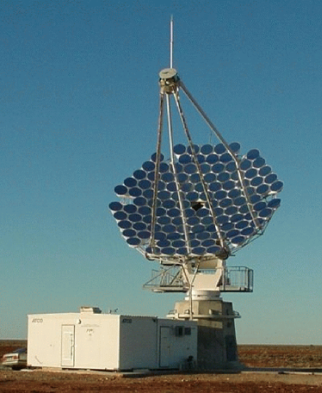
The 7m telescope was expanded to its full 10m diameter by adding small spherical 80cm diameter mirrors made of CFRP (Kawachi et al., 2001). This expansion was done in February 2000 as the first step of the CANGAROO-III project (Fig.1). Now the reflector consists of 114 mirrors arranged on a parabolic surface. The point image size was measured by observing stars with a CCD camera viewing the prime focal plane. It became a little worse, FWHM, than that of the 7m telescope, FWHM. However, Monte Carlo simulation shows this has small effect in analyzing Cherenkov images.
2.2 552 channel camera
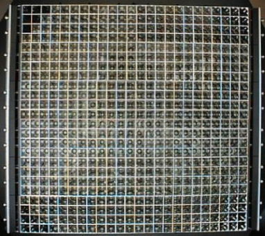
The imaging camera has been upgraded to 552 pixels, each a half-inch photomultiplier (PMT’s, Hamamatsu R4124UV), by adding 10 pixels at each of the four corners (Fig.2). The camera covers a field-of-view of about 3 degrees.
2.3 Electronics
The electronics for the 7m telescope is described in Mori et al. (1999). At the same time as the reflector upgrade, we made some improvement for enhancing the dynamic range in the signal processing (Kubo et al., 2001). Signals from the camera are divided by new active buffers and fed to discriminator modules and new ADC’s. The charge-sensitive ADC modules are housed in the VME-9U standard and have 32 channels of 12-bit resolution. The internal delay of 150 ns for each channel makes external delay cables unnecessary. The minimum gate width is 50 ns. The online CPU has been changed from a Sun SPARC (Solaris) to a Pentium (Linux) with a PCI-VME interface. This reduced the system deadtime significantly.
3 New 10m telescopes
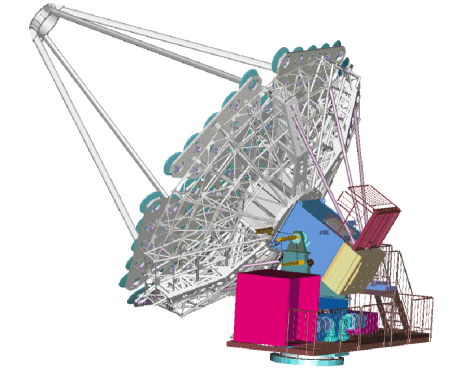
Four telescopes will be set at each corner of a diamond with sides of about 100m. Performance of the system of telescopes is given in detail elsewhere (Enomoto et al., 2001a). Here we describe the major improvements for the telescopes to be installed in 2001 and later (Fig.3).
3.1 Reflector
The reflector design is the same as the first 10m telescope. One hundred and fourteen CFRP mirrors will be arranged to a parabola shape for each telescope (57 m2). The optical quality of mirrors has been improved (Fig.4) by refining the production process. The mirror attitude adjustment system has been redesigned to match our needs and to save cost and weight.
3.2 Telescope control
Each telescope is controlled by a PC running a Linux operating system with a realtime extension (KURT) in alt-azimuth manner. A master PC issue directives to each control PC via a network and tracking modes can be flexibly changed. Clocks are synchronized by NTP software to a GPS receiver.
3.3 Camera
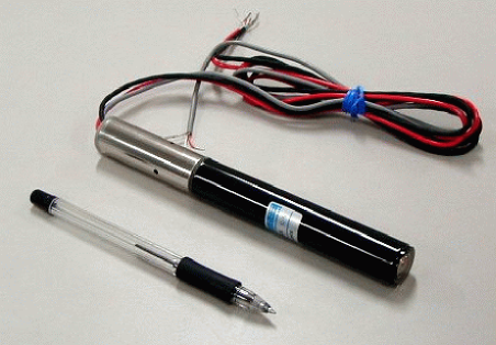
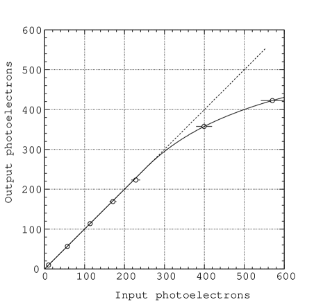
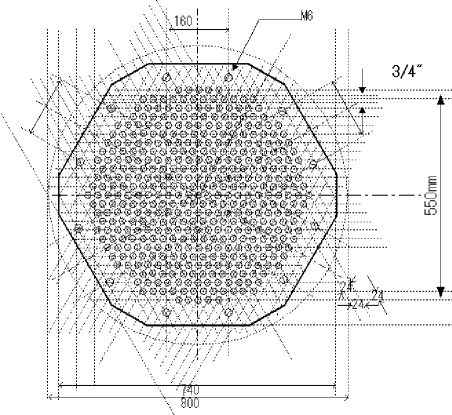
Imaging cameras have been redesigned to cover a wider field-of-view at moderate cost. Hamamatsu R3479UV (3/4”) PMT’s are selected and the base has been designed with a preamplifier inside (Fig.5). A prototype of this assembly showed good pulse height resolution and good linearity beyond the 300 photoelectron level (Fig.6). Four hundred and twenty seven PMT’s are arranged in hexagonal shape with 24mm spacing and cover a field-of-view of about 4 degrees (Fig.7). High voltages for PMT’s are generated in individually-controlled sources (CAEN SY527 /A932) via a VME module (CAEN V288). Positive voltages are supplied to avoid discharging problems between light guides and photocathodes. Each PMT has a newly designed light guide in front of its photocathode thus reducing dead space between photocathodes and collecting twice as many photons (Kajino et al., 2001).
3.4 Electronics
The frontend module has been redesigned. It is a VME-9U card and amplifies signals from PMT assemblies and feeds to an ADC, discriminates them and feeds to a TDC, an internal scaler and a trigger circuit. The VME-based ADC has been improved for faster data transfer compared with those used in the first 10m telescope. VME TDCs (CAEN V673, multievent/multihit, 1 ns resolution) with CERN V430-type crates (with V power). PLD-based pattern trigger modules are under development in order to reduce accidental triggers caused by nightsky background photons. Faster data readout are achieved by use of a VME-based Pentium CPU running a Linux operating system. All the electronics are set on the verandah of the telescope base to save cable length and retain signal bandwidth (Fig.3. Data from each telescopes are collected via network and stored at a central disk. Details are given in Kubo et al. (2001).
3.5 Monitors
Cloud monitors detect infrared radiation from clouds making use of a thermopile module and supply useful information on data quality (Clay et al., 1998). Weather monitors can record temperature, humidity and wind speed. These data are read out via serial line connection and stored for offline analysis. A blue LED light source driven by a fast pulser at the reflector pole works as a field-flattener. Another LED source at a distant hill is used as a total gain calibrator (Patterson et al., 2001). CCD cameras will be equipped to monitor star fields and focal plane images.
4 Schedule
The second 10m telescope will be installed in late 2001. The first stereoscopic observations will start in early 2002. The third telescope will be in place in 2002 and the fourth in 2003. Then the full array will be operational by early 2004.
5 Summary
The CANGAROO-III project to search for high-energy gamma-ray objects in the southern hemisphere with an array of four 10m atmospheric Cherenkov imaging telescopes will be ready in 2004. The final goal will be the energy threshold of 100 GeV and the angular resolution of less than 0.1 degree.
Acknowledgements.
We thank Communication Systems Center, Mitsubishi Electric Corporation, and DSC Woomera for their assistance in constructing the telescopes. This project is supported by a Grant-in-Aid for Scientific Research of Ministry of Education, Culture, Science, Sports and technology of Japan, and the Australian Research Council.References
- Clay et al. (1998) Clay, R.W. et al., Publ. Astron. Soc. Australia, 15, 332, 1998.
- Enomoto et al. (2001) Enomoto, R. et al., in these Proceedings, 2001a.
- Enomoto et al. (2001a) Enomoto, R. et al., Astropart. Phys., in press, 2001b.
- Hara et al. (2001) Hara, S. et al., in these Proceedings, 2001.
- Kajino et al. (2001) Kajino, F. et al., in these Proceedings, 2001.
- Kawachi et al. (2001) Kawachi, A. et al., Astroparticle Phys. 14, 261, 2001.
- Kubo et al. (2001) Kubo, H. et al., in these Proceedings, 2001.
- Kushida et al. (2001) Kushida, J. et al., in these Proceedings, 2001.
- Mori et al. (1999) Mori, M. et al., in Proc. 26th ICRC (August 17–25,1999, Salt Lake City, USA), Vol.5, p.287, 1999.
- Mori et al. (2000) Mori, M. et al., in Proc. GeV-TeV Gamma-ray Astrophysics Workshop (August 13–16, 1999, Snowbird, USA; AIP Conf. Proc. 515), p.485, 2000.
- Mori et al. (2001) Mori, M. et al., in Proc. High Energy Gamma-ray Astronomy (June 26–30, 2000, Heidelberg, Germany; AIP Conf. Proc. 558), p.578, 2001.
- Nishijima et al. (2001) Nishijima, K. et al., in these Proceedings, 2001.
- Okumura et al. (2001) Okumura, K. et al., in these Proceedings, 2001.
- Patterson et al. (2001) Patterson, J.R. et al., in Proc. High Energy Gamma-ray Astronomy (June 26–30, 2000, Heidelberg, Germany; AIP Conf. Proc. 558), p.625, 2001.
- Tanimori et al. (1999) Tanimori, T. et al., in Proc. 26th ICRC (August 17–25,1999, Salt Lake City, USA), Vol.5, p.203, 1999.
- Tanimori (2001) Tanimori, T., to appear in Proc. High Energy Phenomena in the Universe, (January 20–27, 2001, Les Arcs, France), 2001.