the TAMA collaboration
Stable Operation of a 300-m Laser Interferometer with Sufficient Sensitivity to Detect Gravitational-Wave Events within our Galaxy
Abstract
TAMA300, an interferometric gravitational-wave detector with 300-m baseline length, has been developed and operated with sufficient sensitivity to detect gravitational-wave events within our galaxy and sufficient stability for observations; the interferometer was operated for over 10 hours stably and continuously. With a strain-equivalent noise level of , a signal-to-noise ratio (SNR) of 30 is expected for gravitational waves generated by a coalescence of 1.4 -1.4 binary neutron stars at 10 kpc distance. We evaluated the stability of the detector sensitivity with a 2-week data-taking run, collecting 160 hours of data to be analyzed in the search for gravitational waves.
pacs:
04.80.Nn, 07.60.Ly, 95.55.YmIntroduction. — The direct observation of gravitational waves (GW) is expected to reveal new aspects of the universe bun-Thorne . Since GWs are emitted by the coherent bulk motion of matter, and are hardly absorbed or scattered, they carry different information from that of electromagnetic waves. However, no GW has yet been detected directly because of its weakness. In order to create a new field of GW astronomy, several groups around the world are developing laser interferometric GW detectors. Compared with resonant-type GW detectors bun-reso , interferometric detectors have an advantage in that they can observe the waveform of a GW, which would contain astronomical information.
Interferometric GW detectors are based on a Michelson interferometer. The quadrupole nature of a GW causes differential changes in the arm lengths of the Michelson interferometer, which are detected as changes in the interference fringe. Interferometric detectors have been investigated with many table-top bun-tabletop and prototype bun-prototype experiments to evaluate the principle of GW detection and their potential sensitivity to GWs. With the knowledge obtained from these experimental interferometers, several GW detectors with baseline lengths of 300 m to 4 km are under construction: LIGO bun-LIGO in U.S.A., VIRGO bun-VIRGO and GEO bun-GEO in Europe, and TAMA mando-TAMA in Japan. In these detectors, both high sensitivity and high stability are required because the GW signals are expected to be extremely small and rare.
TAMA is a Japanese project to construct and operate an interferometric GW detector with a 300-m baseline length at the Mitaka campus of the National Astronomical Observatory in Tokyo (). In this article, we report on an important achievement in interferometric detectors: the TAMA detector was operated with sufficient sensitivity and stability to observe GW events at the center of our galaxy. The interferometer was operated stably and continuously over several hours in typical cases, and over 10 hours in the best cases. The noise-equivalent sensitivity was at the floor level (700 Hz to 1.5 kHz). With this stability of the sensitivity, TAMA has the ability to detect GW events throughtout much of our galaxy: chirp signals from the coalescence of binary neutron stars or binary MACHO black holes mando-MACHO , and burst signals from supernova explosions.
Detector configuration. — In the interferometer, called TAMA300, the arms of the Michelson interferometer are replaced by 300 m Fabry-Perot arm cavities to enhance the sensitivity to GWs (Fig. 1). The arm cavities have a finesse of around 500, and a cutoff frequency of about 500 Hz; the light is stored in the cavities for about 0.3 msec. Since a high-power and stable laser is required as a light source, we use an LD-pumped Nd:YAG laser with an output power of 10 W mando-10Wlaser1 . In addition, a mode cleaner is inserted between the laser source and the main interferometer to reject higher-mode beams and to stabilize the laser frequency. The mode cleaner of TAMA300 is an independently-suspended triangular ring cavity with a length of 9.75 m mando-10mMC . Electro-optic modulators (EOM) for phase modulation (for mode cleaner and the main interferometer control) are placed in front of the mode cleaner. Thus, the wave-front distortion by the EOM are rejected by the mode cleaner before entering into the main interferometer.
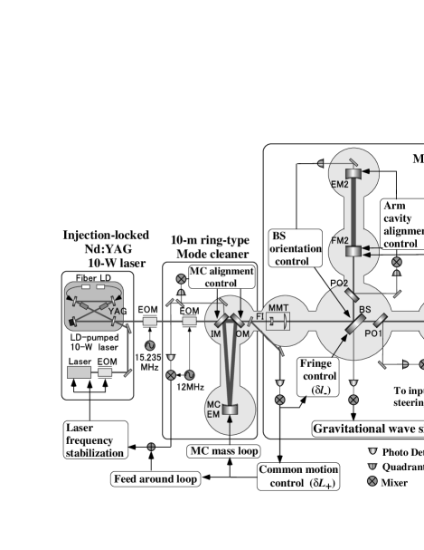
The mirrors of the main interferometer are made of fused silica. Each mirror has a diameter of 100 mm, and a thickness of 60 mm. The mirrors are coated by an IBS (ion-beam sputtering) machine to realize low-optical-loss surfaces mando-mirrorloss2 .
The mirrors of the main interferometer and the mode cleaner are isolated from seismic motion by over 165 dB (at 150 Hz) with three-stage stacks mando-stack and double-pendulum suspension systems mando-sus . The suspension points are fixed to motorized stages, which are used for an initial adjustment of the mirror orientations. The fine position and orientation of each mirror is controlled with coil-magnet actuators; small permanent magnets are attached to the mirror.
The interferometer is housed in a vacuum system comprising eight chambers connected with beam tubes with a diameter of 400 mm. With surface processing, called ECB (Electro-Chemical Buffing), a vacuum pressure of less than Pa is achieved without baking mando-vac2 .
The control system is designed to realize high sensitivity and stability at the same time. It consists of three parts: a length control system to keep the interferometer at its operational point, an alignment control system to realize short-term ( 1 minutes) stability and high sensitivity, and a beam-axis drift control system for long-term ( a few hours) stable operation. A frontal modulation scheme mando-FM is used for the length control; 15.235 MHz phase modulation is used for signal extraction. The differential motion signal of the arm cavities () is fed back to the front mirrors with a bandwidth of 1 kHz. The common motion signal () is fed back to the mode cleaner and the laser source to stabilize the laser frequency. The motion in the Michelson interferometer part () is fed back to the beam splitter.
An alignment control system is necessary for stable and sensitive operation because angular fluctuations (about several rad) of the suspended mirrors excited by seismic motion make the interferometer unstable. The control signals are extracted by a wave-front-sensing scheme mando-wfs , and fed back to each mirror; the angular motions are suppressed by over 40 dB to rad in root-mean-square.
Low-frequency drift control of the laser beam axis plays an important role in maintaining long-term operation. The beam axes are controlled with 300 m optical levers; the beam positions of the light transmitted through the arm cavities are monitored with quadrant photo detectors, and are fed back to the input steering mirror and the beam splitter of the main interferometer.
The data-acquisition system comprises a high-frequency part for the main signals and a low-frequency part for detector diagnostics. The main output signals of the interferometer are recorded with high-frequency A/D converters ( samples/sec, 16 bit) after passing through whitening filters and 5 kHz anti-aliasing low-pass filters. Seven channel signals are recorded together with a timing signal, which provides a GPS-derived coordinated universal time (UTC) within an accuracy of 1 sec. Along with the high-frequency system, 88 channels of monitoring signals are collected with a low-frequency data-acquisition system for interferometer diagnosis.
Detector noise level. — Figure 2 shows the typical noise level of TAMA300 (black curve). The displacement noise level of the interferometer is , which corresponds to in strain. Almost all of the noise sources which limit the interferometer noise level have been identified. The gray curve in Fig. 2 represents the total contribution of the identified noise sources: seismic motion ( 30 Hz), alignment-control noise (30 Hz300 Hz), Michelson phase-detection noise (300 Hz 3 kHz), and the laser frequency noise (3 kHz ). The seismic noise and the laser frequency noise are estimated to satisfy the design requirements in the observation band (around 300 Hz).
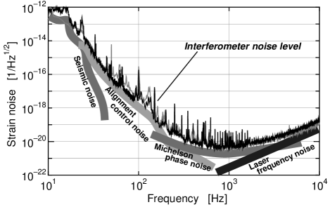
Though the alignment control system is indispensable for the stable operation of the interferometer, this system can introduce excess noise to the interferometer mando-ali . The noise in the alignment control error signal causes displacement noise by coupling with mis-centering of the beam on a mirror, and efficiency asymmetries of the coil-magnet actuators on a mirror. In order to reduce this noise, the actuator balances are adjusted so that the rotational center is at the beam spot on a mirror. In addition, the beam position on each mirror is controlled to be still by the beam-axis control system.
The noise floor level is limited by the phase-detection noise of the Michelson part of the interferometer. Phase changes in the light caused by GW are amplified in the arm cavities, and detected by the Michelson interferometer. In order to realize the designed detector sensitivity, the noise level of the Michelson part of the interferometer should be limited only by the shot noise in the observation band. However, in TAMA, as well as by the shot noise, it is currently limited by the scattered light noise caused by the anti-reflection coating of the mode-matching telescope (MMT in Fig. 1) between the main interferometer and the mode cleaner. To realize the designed detector sensitivity which is purely limited by the shot noise, the scattering noise should be removed.
Stability of operation. — With the total system described above, we performed a 2-week observation run from August 21 to September 3, 2000. Figure 3 shows the operational state during the observation; the gray and black boxes represent the time when the interferometer was operated and when the data were taken, respectively. The time is shown both in UTC and in Japan standard time (JST). The interferometer was operated for over 160 hours, 94.8% of the total data-taking-run time. (Periods of continuous lock shorter than 10 minutes are not included.) We operated the interferometer mainly during the night for the efficient collection of high-quality data. During the observation, the noise level was degraded slightly from the Fig. 2 level, because of electronic noises by many cables connected to the interferometer for data-taking. The longest continuous locking time was over 12 hours (several hours in typical cases); the main cause of loss of lock of the interferometer was large seismic disturbances, including earthquakes (closed circles), and rather large drifts of (triangle marks). From a coincidence analysis of signals from seismometers placed at the center and end rooms, we found that the interferometer was knocked out of lock by accelerations of 12 mgal (1 10 Hz frequency range). The interferometer was also knocked out of lock by large drift of ; a drift of over 120 m could cause saturation in the feedback loop. The other causes of loss of lock are thought to be local seismic disturbances caused by human activities, spikes due to instability of the laser source, and so on.
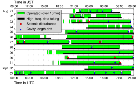
The interferometer noise level was stable thanks to the alignment and drift control systems; the drift of the noise level averaged for 1 minute was kept within a few dB, typically. During the 2-week data-taking run, the noise floor-level drift was kept within 3 dB for about 90% of the total operation time. In addition, in typical cases, the noise level was easily recovered without any manual adjustment after the unlock and relock of the interferometer with these automatic control systems. The noise level of the interferometer was calibrated continuously using a sinusoidal calibration signal at 625 Hz; from the amplitude and phase of this peak signal, we estimated the optical gain and cut-off frequency of the cavity. The Gaussianity of the noise level was evaluated every 30 seconds. We observed about 10 non-Gaussian (confidence level of 99%) events per hour in this observation run. The non-Gaussian noise will be partly removed by veto analysis using other channels, such as seismic motion, laser intensity noise, contrast fluctuation, and a signal.
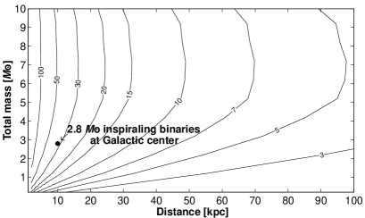
In order to check the GW-detection ability of TAMA, we calculated the expected SNR for GW from inspiraling binaries with the interferometer noise spectrum and calculated chirp signals (Fig. 4) mando-Tago . Here, we assumed optimally-polarized GWs from an optimal direction for the detector. TAMA would detect GW events at the Galactic center with sufficient SNR; the SNR is about 30 in the case of chirp signals from a coalescence of 1.4 -1.4 binary neutron stars at 10 kpc distance. With the burst signals from supernova explosions, TAMA would detect GWs with a strain amplitude of (which corresponds to a mass energy of , again at the distance to the Galactic center) with a SNR of about 10 at the frequency band from 700 Hz to 1 kHz. However, as well as a veto analysis with the other recorded channels, a coincidence analysis with other GW detectors or other astronomical channels will be required for the detection to reject non-Gaussian noise background.
Conclusion. — The TAMA300 interferometer has been operated stably for over 10 hours without loss of lock, with a noise-equivalent sensitivity of at the floor level. With this sensitivity and stability, TAMA has the ability to detect GW events within our galaxy, though such events are expected to be very rare. In order to increase the detection probability for GW events farther away from our galaxy, we are improving the detector sensitivity and stability further. Almost all of the noise sources which limit the detector sensitivity have been identified. The noise level will be improved with new alignment control filters and a reflective mode-matching telescope. The stability of the operation will be improved further with installation of an active isolation system and replacement of a suspension system by one with effective damping.
The achieved performance of the TAMA detector is a significant milestone in the quest for direct detection of GW, and for the establishment of GW astronomy with interferometric detectors.
The TAMA project is supported by a Grant-in-Aid for Creative Basic Research from the Ministry of Education.
References
- (1) K. S. Thorne, in Three hundred years of gravitation, edited by S. Hawking and W. Israel (Cambridge University Press, 1987), p. 330-458.
- (2) J. Weber, Phys. Rev. Lett. 22, 1320 (1969), Z. A. Allen et al., Phys. Rev. Lett. 85, 5046 (2000).
- (3) G. E. Moss, L. R. Miller, and R. L. Forward, Appl. Opt. 10, 2495 (1971).
- (4) A. Abramovici et al., Phys. Lett. A 218, 157 (1996), D. Shoemaker et al., Phys. Rev. D 38, 423 (1988), S. Sato et al., Appl. Opt. 39, 4616 (2000), D. I. Robertson et al., Rev. Sci. Instrum. 66, 4447 (1995), R. Takahashi et al., Phys. Lett. A 187, 157 (1994), P. Fritschel et al., Phys. Rev. Lett. 80, 3181 (1998), K. Kawabe et al., Appl. Phys. B 62, 135 (1996), M. Ando et al., Phys. Lett. A 248, 145 (1998).
- (5) A. Abramovici et al., Science 256, 325 (1992).
- (6) The VIRGO collaboration, VIRGO Final Design Report, VIR-TRE-1000-13, 1997.
- (7) K. Danzmann et al., Proposal for a 600m Laser-Interferometric Gravitational Wave Antenna, Max-Planck-Institut für Quantenoptik Report 190, 1994.
- (8) K. Tsubono, in Gravitational Wave Experiments, edited by E. Coccia, G. Pizzella, and F. Ronga, (World Scientific, 1995), p. 112-114, K. Kuroda et al., in Gravitational Waves: Sources and Detectors, Edited by I. Ciufolini and F. Fidecaro C (World Scientific, 1997), p. 100-107.
- (9) T. Nakamura, M. Sasaki, T. Tanaka, and K. S. Thorne, Astrophys. J. 487 L139 (1997).
- (10) S. T. Yang et al., Opt. Lett. 21, 1676 (1996).
- (11) A. Telada, The Graduate University for Advanced Studies Ph. D thesis, 1997.
- (12) S. Sato et al., Appl. Opt. 38, 2880 (1999).
- (13) R. Takahashi et al., in Gravitational Wave detection, edited by K. Tsubono, M.-K. Fujimoto, and K. Kuroda (Universal Academy Press, 1997), p. 95-102.
- (14) A. Araya et al., in Gravitational Wave detection, edited by K. Tsubono, M.-K. Fujimoto, and K. Kuroda (Universal Academy Press, 1997), p. 55-62.
- (15) Y. Saito, et al., Vacuum 53, 353 (1999).
- (16) M. W. Regehr, F. J. Raab, and S. E. Whitcomb, Opt. Lett. 20, 1507 (1995).
- (17) E. Morrison, et al., Appl. Opt. 33, 5037 (1994).
- (18) S. Kawamura and M. Zucker, Appl. Opt. 33, 3912 (1994).
- (19) H. Tagoshi, et al, Phys. Rev. D (printing).