Kinematic Projecting of Pulsar Profiles
Abstract
We suggest a technique for construction of profiles of incoherent pulsar emission using instantaneous angular distribution indicatrix of radiation from relativistic source moving in the neutron star magnetosphere. In the general case the indicatrix depends on the kinematic parameters of radiation source such as velocity and acceleration. The method is illustrated by calculation of the profiles of pulsar radiation based on synchrotron radiation indicatrix. This technique can be easily generalized for the case of other types of relativistic particles radiation. The considered profiles are compared with observed ones. A good agreement was found with profiles of -pulsars — Geminga, Crab and Vela.
1 Introduction
There is no clear conception of the nature of pulsar electromagnetic radiation. We accept the well known point of view suggested by I.S. Shklovsky Shklovsky that at least the high frequency part of radiation represents the incoherent synchrotron radiation.
There are different models of pulsar radiation based on various physical processes which are sometimes contradictory and insufficiently conditioned. We suggest a technique of kinematic projecting of synchrotron radiation Bagrov (1965) which gives the pulsar radiation profiles including the phase dependence of polarization characteristics Bagrov et al. (1972, 1974); Bordovitsyn . Then one can analyze the coherence effects and possible mechanisms of pulsar radiation.
The suggested technique of determination of the pulsar radiation profiles is as a matter of fact a kinematic projecting of relativistic radiation regardless to the specific source of the radiation. The role of such sources of radiation can play relativistic charged particles electrons, magnetic particles (neutrons) or even bunches of those particles. The main source of information in this technique is the highly directed indicatrix of the angular distribution of instantaneous power of relativistic radiation, which is specified by the kinematic and dynamic characteristics of the emitting object in every specific case. It is known Shklovsky ; Manchester and Taylor that there are two models of radiation geometry. The first one is due to two beams of curvature radiation associated with the magnetic poles. The second one is associated with synchrotron radiation in a plane orthogonal to the magnetic axis of pulsar. We restrict our consideration with the second model of radiation, though it is possible to apply this technique in the first case too.
2 Transformation of angular distribution into the pulse profile
We start from the indicatrix of synchrotron radiation averaged over the period. Because of high energy main part of radiation is concentrated near the plane of symmetry which we call the light plane. Directions, assigned to radiation maximum, are situated in the light plane. Axis orthogonal to the light plane coincides with the direction of pulsar magnetic moment . Vector is precessing around the pulsar axis of rotation with the angular velocity .
We assume that the angular velocity of the emitting particles is much more than .
| (1) |
here is the charge, is the mass of rest, is the speed of light, is the relativistic Lorentz factor, , is the particle velocity. It follows from the last inequality that
| (2) |
Let us estimate the order of -factor satisfying the last condition. It can be taken for pulsars that , Oe not far from the surface and Oe in the periphery of magnetosphere (near the light cylinder). Then the condition 2 gives the value , i.e. condition 2 is always satisfied in available relativistic and even ultrarelativistic case.

We introduce the coordinate system shown in Fig. 1. Direction of the angular velocity of pulsar is parallel to -axis. The pulsar magnetic axis defined by unit vector is specified by the angles and . The unit vector of the observer’s direction is given by the angles and . We assume that vector is situated in the plane at the moment .
We present the angular distribution of radiation averaged over the period of particle motion in a form
where is the total power of radiation, which is relativistic invariant, is the function of the angular distribution of radiation normalized to unity
It is obvious that the angle varies in the course of time, as the unit vector setting the position of light plane is precessing around the axis. It is easy to show that
| (4) |
If we know , we determine the radiation profile and the power emitted in the directions of the angle interval . The maximum of radiation will be observed at the moment of intersection of the observation direction by the light plane when , i.e. when
| (5) |
The latter equation has a solution when .
Equation (5) has two roots within the precession period which are equal at . In other words the light plane intersects the observation direction twice within the period, if the angle between the vector and plane is less than .
If the light plane intersects the observation direction (or touches it), then the angle can be chosen such that the observation direction has been situated in the light plane at . Under this initial condition the radiation pulse takes on the maximum value at . Thereat it follows from the equation (5) that
| (6) |
Another form of relation (6) is possible
It follows from equation (6)that for the same acute angles and the term takes equal values within the range , i.e. and , which corresponds to two possible intersections of the observation direction and the light plane. At we have . In this case the observation direction only touches the light plane. Note that equation (6) is symmetric relative to angles and . It means that the positions of the two peaks of profiles will not change if we swap and . The case of is special. It follows from equation (4) that in this case const and pulsar is observed as a source of synchrotron radiation with constant luminosity and angular distribution of radiation defined by relation (3).
In the ultrarelativistic case of the main part of radiation is concentrated near the light plane . Thereat duration of the radiation pulse is much less than . It allows to expand the function in a series in small angles , or small . To a first approximation in we get
| (7) |
Specifying the initial conditions in accordance with equation (6), we have
| (8) |
or, with account of (6),
We introduce another angular variable
| (9) |
The variable has a sense of angular velocity at which the observer’s direction intersects the light plane. The highest velocity corresponds to passage through the radiation maximum. In this case and are associated with the direction in the light plane.
Substituting equations (8) and (9) into equation (3) we find the radiation profile in a form
| (10) |
If or then and we have to take into account the terms of higher order in the expansion in .
Figs 2 display the synchrotron radiation profiles correspond to weakly relativistic electron at and at various values of angle and fixed . Fig. 2 a shows the case when the angle i.e. when vector is orthogonal to rotation axis. If the observer is situated in the direction of axis (), radiation of constant intensity is registered. As the angle increases the radiation is modulated at the frequency of and the effect of glimmer pulsar is observed. One can see that the greater is the angle the deeper is the glimmer modulation.
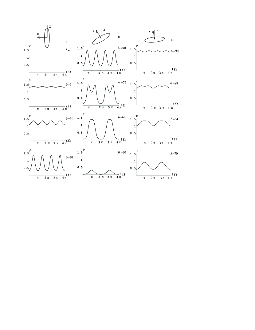
If the angle between pulsar magnetic axis and rotation axis is acute (see Fig. 2 b), then the distance between the peaks of radiation within a period decreases with increasing of angle , and at they merge in one maximum. At further decreasing of the light plane does not intersect the observer’s direction and the amplitude of splashes falls quickly off. When the angle between the pulsar magnetic axis and rotation axis is small, the light plane intersects the observation direction under a small angle (see Fig. 2 c). In consequence the splashes duration increases considerably and the depth of modulation falls off. Thereby the main part of radiation is concentrated near the plane orthogonal to the rotation axis ().
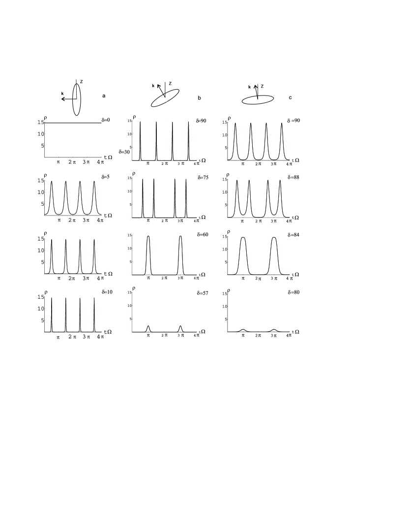
Fig. 3 shows the radiation profiles of ultrarelativistic particles (). They are distinguished by deeper modulation and small pulse duration.
In Fig. 4 the light profiles calculated by use of approximated equation (10) (solid line) and exact equation (3) with account of (4) (dashed line) are shown for particles moving at the velocity . We see that even for moderately relativistic particle these equation are in a good agreement.

3 Comparison with the observed profiles
We have considered a simple model of pulsar emission. Some of the obtained profiles are close in shape to really observed profiles. In this section we compare the profiles of -ray pulsars, the Crab, Vela and Geminga with the profiles obtained from synchrotron radiation indicatrix. As one can see from Figs. 3 and 4 the variation of angles and gives a wide variety of profiles. But it does not mean that you can produce any profile in this way. In particular, profiles obtained by this method have a certain relationship between the width of peaks, phase position and the level of plato between them. Thus, not every observed profile can be built with help of used model. But if a calculated profile fits an observed one, it can mean that the suggested model is adequate and we obtain some information about angles and .
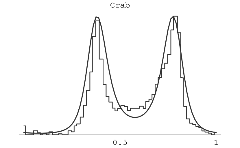
Figs 5 and 6 show calculated and observed profiles for three well known -ray pulsars. The energy interval for electrons (or positron) were chosen for following reason. Most pulsars exhibit two sharp peaks within a period if the energy of photons lies in the region MeV. Knowing the critical frequency of synchrotron radiation we can estimate the Lorentz-factor of particles . For the magnetic field of order Oe we obtain or for the particle velocity . Specific values of for Figs 7 were selected in a way to obtain the best fit of peaks width. It is obvious that the greater is the particle energy the narrower are the peaks.
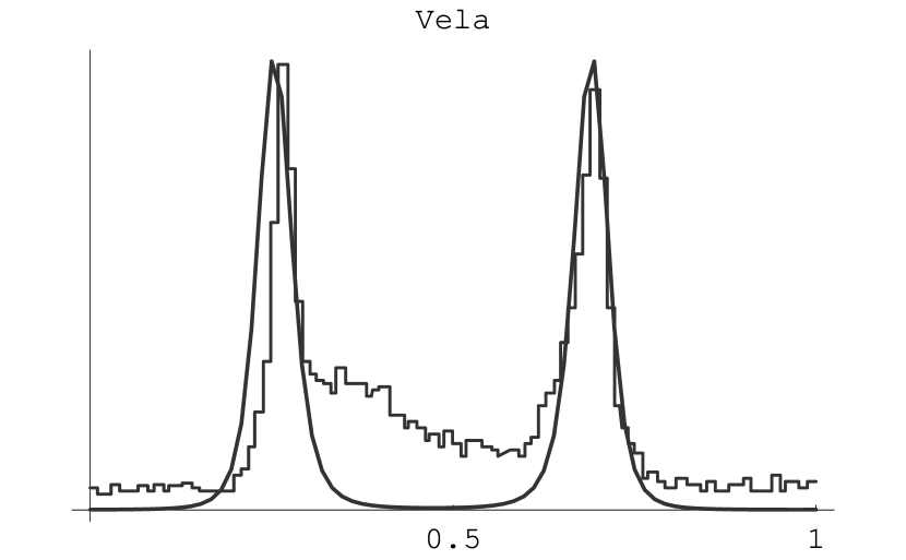
It is believed that the pulsar in the Crab Nebula has an inclination angle close to . That is why we choose . Then the best fit to the observed pulse profile measured by BATSE Fishman gives the value see Fig. 5. The next figure shows the Vela pulse profile for energy of photons above 100 MeV detected by EGRET Fierro et al. along with calculated profile for angles , and . The difference occurs in a bridge between the two pulses. It can be caused by the dispersion of particle orbits in the pulsar magnitosphere.
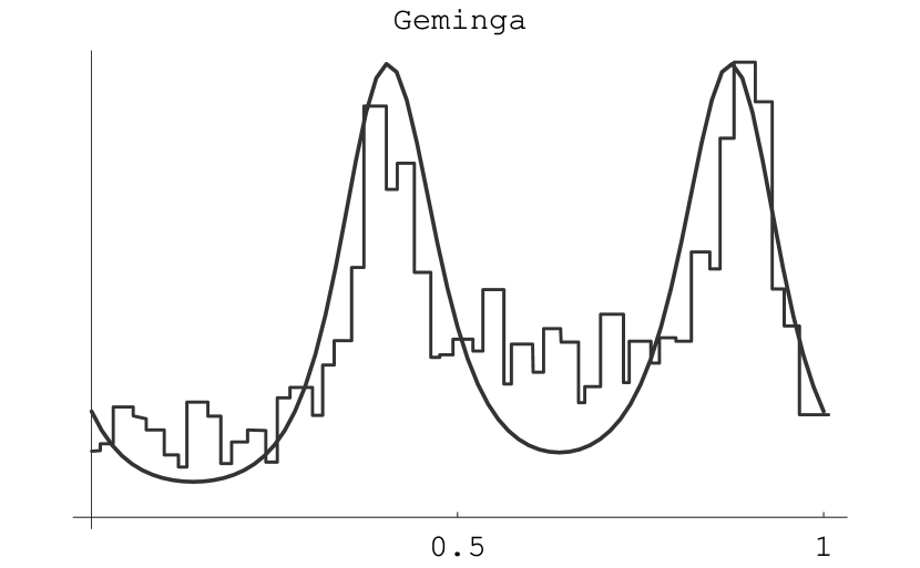
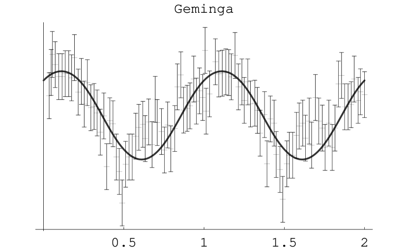
Next two figures show Geminga profiles. The first one of Fig 6 displays observed -profile for MeV Daugherty and Harding along with calculated one for , and . Soft X-ray profile is plotted in the second of Fig. 6 in the 0.53–1.5 keV band measured by ROSAT Halpern and Ruderman and a profile calculated for angles , and . We see good agreement between the model and observed profile though it is thought that the soft X-ray radiation is due to thermal black body emission Halpern and Ruderman .
4 Discussion
The profiles shown on Figs 5 and 6 are calculated for moderately relativistic electrons. In doing this we tried to fit the shape of profiles. But all the calculations were made for a single particle. It is evident that in a real situation radiation is emitted by an ensemble of particles with a spread in energies and orbit orientation. It is evident that on averaging over this parameters the pulse width can grow significantly. But without regard on averaging we can obtain some information about the pulsar magnetic axis orientation from the relative position of pulses in the radiation profile. According to equation (5) the maximum of radiation occurs at given by
| (11) |
If we know the phase distance between the pulses, we will find the relationship between angles and by use of equation (11). Here we suppose that -radiation of pulsars is a synchrotron radiation of particles with their orbits orthogonal to the magnetic axis of pulsar. The probability of detection of such pulsar in a -ray band according to this model is equal to . Thus, with the most probability we can detect pulsars with its magnetic axis orthogonal to the axis of rotation. Thereby the gap between pules in -ray region should be close to 0.5 of period. That is what we see in most cases of detected -ray pulsars.
The discussed model does not pretend to give entire interpretation of the pulsar radiation. The main purpose of this paper is to show how to find the light profile of a rotating source with an indicatrix of radiation which is given in a rest frame. We chose the synchrotron radiation mechanism as an widely spread example. Considered method can be used for curvature radiation or more complicated source of radiation.
References
- (1) Shklovsky, I.S. 1977 Stars, Nauka, Moscow, p. 384.
- Bagrov (1965) 1965 Bagrov, V.G.Optika i spektroskopija. V. 18. Vyp. 4. 541.
- Bagrov et al. (1972) 1972 Bagrov, V.G., Bordovitsyn, V.A., Kopytov, G.F.Izv. Vuzov. Fiz. V. 15. N 6. 86.
- Bagrov et al. (1974) Bagrov, V.G., Bordovitsyn, V.A., Kopytov, G.F. and Epp, V.Ya. 1974 Izv. Vuzov. Fiz. V. 17. N 1. 46.
- (5) Bordovitsyn, V.A., ed. 1999 Synchrotron radiation and its development. Singapore: World Scientific.
- (6) Manchester, R.N., Taylor, J.H. 1977 Pulsars. Freeman and Company.
- (7) Fishman, G. 1992 GRO Newsletter, 1, 6.
- (8) Fierro, J.M., Michelson, P.F. and Nolan, P.L. 1992 ApJ, 1, 6.
- (9) Daugherty, J.K. and Harding, A.K. 1996 ApJ 458, 278.
- (10) Halpern, J.P. and Ruderman, M. 1993 ApJ 415, 286.