Spatially resolved spectroscopy of Cassiopeia A
with MECS
on board BeppoSAX
We have performed the first detailed spatially resolved spectroscopy of Cas A in the 1.6–10 keV energy range, using data taken with the MECS spectrometer on board the BeppoSAX Observatory. The well calibrated point spread function in the central region of the MECS allowed us to perform a spatial deconvolution of the data at full energy resolution. We eventually generated a set of spectra, covering a region of 3 radius around the centre of Cas A. The results obtained by fitting these spectra using a non-equilibrium ionisation plasma model and a power law, improve our knowledge about chemical and physical parameters of the Cas A SuperNova Remnant: (i) a single thermal component is sufficient to fit all the spectra; (ii) is rather uniformly distributed with a minimum in the east and a maximum in the west, and no evidence is found for high expected from the interaction of the main shock with the ISM; (iii) from the distribution of the values of the ionisation parameter we infer the presence of two distinct components: the first () in the range 1–10 cm-3, the second () with values ten times higher; if we associate component to the CSM and component to the ejecta, the mass ratio 1/10 indicates a progenitor star that lost only a small fraction of the envelope during its pre–SN life. In this hypothesis the distribution of component across the remnant suggests that the explosion was not spherically symmetric; (iv) the distribution of abundances indicates that we are detecting a CSM component with almost solar composition, and an ejecta component enriched in heavier elements. Abundances found for –elements are consistent with the current view that Cas A was produced by the explosion of a massive star. A low overabundance can be an indication that at the moment of the explosion the mass-cut was rather high, locking most of the produced 56 into the stellar remnant.
Key Words.:
ISM: SuperNova Remnants – Cas A – X-rays: ISM – methods: data analysis – techniques: image processing – techniques: spectroscopyM.C. Maccarone, cettina@ifcai.pa.cnr.it
1 Introduction
Cassiopeia A (Cas A), the youngest known SuperNova Remnant (SNR) in our galaxy, is an object investigated at several wavelengths. It has the appearance of a broken shell with average radius of 1.7 (Holt et al., (1994); Vink et al., (1996)) around its expansion center that Reed et al. (1995) found located at RA2000=, DEC2000=. Detailed observations at optical wavelengths show a complex morphology, not spherically symmetric, with two northwest (NW) and southeast (SE) emission regions moving outward from the remnant center in accordance with their relative average Doppler motion (Anderson et al., (1991); Reed et al., (1995); Lawrence et al., (1995); Fensen & Gunderson, (1996)). A similar morphological complexity comes out in the X-ray band as observed by ASCA at the moderate spatial resolution of 3 (Holt et al., (1994); Fujimoto et al., (1995); Vink et al., (1996); Hwang & Gotthelf, (1997)). BeppoSAX (Boella et al., 1997a ) observed the source giving interesting results either in the spectral and in the spatial analysis. In particular, the maps obtained in the energy range 1.6–10 keV (Maccarone et al., (1998); Vink et al., (1999)) with the Medium Energy Concentrator Spectrometer MECS instrument (Boella et al., 1997b ) show that the spatial distributions of , , , and emission lines do not differ very much each other. In addition, the presence of seems to extend further east than for the other elements. Such results have been confirmed recently by the Chandra X-ray observatory that, with its imaging capability of 0.5, provided well detailed maps of the remnant and discovered a point-like source near its center (Hughes et al., (2000); Chakrabarty et al., (2000); Hwang et al., (2000)).
The broad band BeppoSAX spectrum of the whole source (Favata et al., (1997)) presents a high energy component well modeled by a power law of spectral index 2.95. This component has been localized by Vink et al. (1999) mainly in the southern and western regions. Indeed the MECS spectra of these regions are somewhat harder than the average and almost featureless above 4 keV.
In this paper we present results about the spatially resolved spectroscopy of Cas A in the MECS energy range 1.6–10 keV, at the resolution of 1.5. Data set and data reduction are presented in Sect. 2 together with a brief description of the software environment. Image and spectral analyses are described in Sect. 3 and Sect. 4, respectively. Results are discussed in Sect. 5 while conclusions are presented in Sect. 6. The treatment of errors is in Appendix A.
2 Observations and Data Reduction
The Medium Energy Concentrator Spectrometer MECS is one of the narrow field instruments on board BeppoSAX. The MECS consists of three units (ME), each composed of a grazing incidence mirror unit with a position sensitive gas scintillation proportional counter located at the focal plane. The MECS field of view covers a radius of 28 with position resolution of 1.5; inside the central circular window of 10 (delimited by a strongback structure) all the detector parameters are well defined.
The three ME units were all together active till May 6, 1997, when ME1 unit was switched off, due to a failure in the high voltage supply of the gas cell unit. ME2 and ME3 units continued to work normally.
The on-axis Point Spread Function (PSF) of the MECS can be modeled as sum of two components: a gaussian, and a generalized lorentzian. For each ME unit, at a given energy and at a given distance from the detector center, the complete analytical expression for the on-axis PSF is (Boella et al., 1997b ):
where , , and depend on the ME unit and are algebraic functions of the energy. The dependence from the unit can be averaged in the formulation: this allows us to consider a single PSF at each given energy. Moreover, the on-axis PSF can be considered valid within a radius of 12 from the detector center (Molendi et al., (1997); Chiappetti et al., (1998)).
Table 1 lists the data set reference codes used for the analysis presented in this paper. MECS data were reduced by using a standard procedure111http://www.sdc.asi.it/software/cookbook with appropriate selection criteria so to avoid the South Atlantic Anomaly and to obtain the maximum rejection of background particles. A further selection was applied to take into account only data related to the orbital periods in which the Z star tracker (aligned with the narrow field instruments) was in use; in this case the attitude reconstruction achieves an uncertainty of the order of 30 inside the strongback region. Under these conditions, the total exposure time for the MECS was 128 000 s, the net exposure time for each observation is listed in Table 1.
| Obs. | Observ. | Observ. | Archival | Exposure | ME |
|---|---|---|---|---|---|
| Prog. | Date | Period | Code | (s) | units |
| SVP | 06aug96 | 743 | 30011002 | 27574 | 1,2,3 |
| SVP | 07aug96 | 745 | 30011001 | 26639 | 1,2,3 |
| SVP | 11sep96 | 899 | 30011003 | 16629 | 1,2,3 |
| SVP | 11sep96 | 901 | 30011003 | 16595 | 1,2,3 |
| AO1 | 26nov97 | 2990 | 30159001 | 40789 | 2,3 |
Data reduction has been carried out using the SAXDAS v.1.2.0 package, developed under the FTOOLS environment. Image analysis and spectra generation were carried out under MIDAS-97NOV environment222http://www.eso.org/midas; the context saxmecs333http://www.ifcai.pa.cnr.it/sax/saxmecs/saxmecs.html has been used to convert data in MIDAS format, to merge MECS observations in images, to generate the PSF as function of energy, and to accumulate the final spectra.
The adopted deconvolution procedure is based on the Lucy’s deconvolution method (Lucy, (1974)), as implemented in MIDAS-97NOV, and it can be fruitfully applied on sources presenting an extended and structured morphology. With respect to our previous analysis (Vink et al., (1999)), we reconsidered the deconvolution parameters: in particular, we rebinned data to 24 per pixel and performed deconvolution at each energy channel with the monochromatic PSF computed for that channel, as detailed in Sect. 3.
The spectral analysis has been performed with the XSPEC v.9.00 software package.
3 Image Analysis
To enhance the morphology of the Cas A spatial emission in the energy range 1.6–10 keV at the resolution of the MECS Pulse Invariant (PI) channel, we adopted the following procedure: for each PI channel in the chosen energy range (PI channel from 32 to 214) we have (i) selected data from each observation, (ii) converted data in X,Y sky pixels images, (iii) merged and rebinned images to improve statistics, (iv) generated the appropriate PSF. We then deconvolved each monochromatic rebinned image with its proper monochromatic PSF for a suitable number of iterations.
Rather large inaccuracies are present in the aspect solution of our original Cas A data set, particularly in the last observation (AO1) made after a gyroscope failure. To overcome the problem, present whenever we need to merge spatial data coming from different observations, we used a procedure similar to that adopted in Vink et al. (1999) and detailed in Maccarone & Mineo (1999)444 http://www.ifcai.pa.cnr.it/cettina/papers/CasA-report2.ps.gz.
3.1 The Deconvolution Algorithm
To be successfully applied, the Lucy’s deconvolution algorithm needs to be properly tailored taking into account the PSF characteristics, the spatial region of Cas A we are interested in, the statistical significance level we are dealing with, and the number of iterations necessary to reach convergence.
The spatial region of Cas A we are interested in is all inside the inner strongback window and it is centered very near to the detector center. Therefore, the radial description of the on-axis PSF can be successfully used in the deconvolution process. We applied the deconvolution algorithm to each PI channel within the chosen energy range by using the monochromatic PSF corresponding to that channel. The total number of counts within the interested region is about distributed over all the PI channels with a maximum of and a minimum of counts.
To improve statistics, we compacted both PSF and observational data images by a factor of 3. This corresponds to rebin their stepsize from 8/pixel to 24/pixel, and to obtain a well-deconvolved spatial region of 10 radius.
To define what number of iterations must be used in the deconvolution algorithm, we adopted a convergence criterium based on the relative change between images produced by two consecutive iterations. The iterations can be stopped when a given level of convergence for the maximum relative change is reached. From previous checks (Maccarone, (1998); Vink et al., (1999)), we noted that a maximum of 30 iterations is sufficient to enhance the morphology of the Cas A emission regions at higher energies (further iterations produce small corrections that tend to match the statistical fluctuations) while, at lower energies a greater number of iterations (some hundreds) is necessary to reach convergency. In the case of the Cas A data images analyzed here with stepsize of 24/pixel at the resolution of the MECS PI channel, a number of 200 iterations is sufficient to reach convergency at lower energies. To automatize the full deconvolution procedure we then choose to apply 200 iterations for any energy channel, without any risk of compromising the results for the higher energy channels. This choice was also supported by the comparison (evaluated via a standard function at each i-th iteration) between the input image and the convolution of the i-th deconvolved image with its proper PSF (Maccarone & Mineo, 1999).
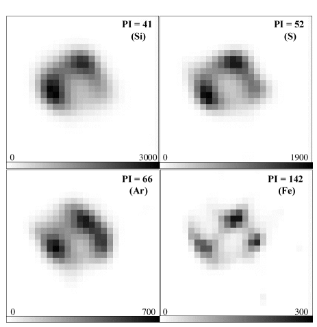
Fig. 1 shows the results after 200 iterations on the images at the energy of , , , and lines. The four monochromatic images present the same morphological structure already illustrated in Fig. 3, left panels of our previous paper (Vink et al., (1999)), although the setting of the deconvolution parameters are sligthly different: 33 compacted pixels and full spectral resolution in this paper, 22 compacted pixels and wide energy bands in our previous paper. From the image analysis point of view, the setting used here gives results in perfect agreement with those obtained in our previous paper; at the same time this setting allows us to perform a better spatially resolved spectroscopy at 1.5 resolution level.
4 Spectral Analysis
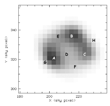
The set of Cas A images obtained from the deconvolution procedure has been organized in a position-energy cube (X, Y, E) from which we have accumulated spectra relative to each X,Y pixel in the spatial region of interest. To work with a good statistical signal we have only considered spectra with total counts greater than 800, reducing to 182 the final number of spatially resolved spectra to be analyzed. The window on which we have performed the spatially resolved spectroscopy then covers a region of 3 radius around the Cas A expansion center. In sky pixels, the coordinates of this center are X209, Y327. Fig. 2 shows the map of the total counts of the 182 selected pixels.
Statistical errors on the counts have been increased to take into account the systematics of the deconvolution procedure (see Appendix A); spectra have been rebinned to have at least 20 counts per energy bin.
Cas A is a strong source and the MECS background subtraction is not a relevant problem even if the deconvolution procedure acts on the spatial distribution of the background, moving counts from the external regions toward the center. We evaluated the background level in the worst case for which all counts within the well-deconvolved region (10) are placed under the source. Under the simplified hypothesis of an uniform background, the level is of the order of counts/s/pixel. We then ignored the background subtraction in our spectral analysis.
In the fitting procedure we used the MECS response matrix relative to an on-axis point source with an extraction circle of 10 radius for all spectra, while the deconvolution was applied using a PSF defined in a squared area: this difference in geometry introduces an under-estimation of the effective area less than 1% in the spectral analysis.
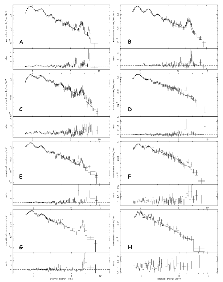
Fig. 3 shows a selection of spectra extracted at the positions marked with the corresponding letter in Fig. 2. It is evident that Cas A emission has not uniform spectral characteristics. In particular, as suggested by Vink et al. (1999) and Hughes et al. (2000), two main emission mechanisms can be identified: a thermal process, underlined by the presence of emission lines and coincident with the broken shell (Fig. 3-A, B, C, E, G), and an emission process characterized by the absence of strong lines (Fig. 3-D, F, H) and essentially located in the central region between the main peaks (Fig. 2).
To fit all spectra, we properly implemented in the fitting code a model of emission from a non-equilibrium ionization (NEI) plasma. The low energy absorption has been constrained within the range 0.9–1.71022 cm-2, slightly wider than the range found by Keohane et al. (1996). The abundances of , , ,, and have been left as free parameters and allowed to vary in the range 0.02–20 (with respect to solar). Moreover we added to the thermal model a power law to take into account the 20–80 keV emission found by Favata et al. (1997). The parameters of the power law are not free in the fitting procedure. In fact, none of the MECS deconvolved spectra has enough statistical significance to justify the presence of a second spectral component (e.g., the power law) superimposed to the thermal emission model.
The spectral index has been fixed at the value of 2.95 as quoted in Favata et al. (1997); the normalization has been computed by assuming that the whole remnant contributes to the high energy component and that the emissivity of this component is proportional to the MECS flux detected in each pixel. In the framework of the present analysis, we realized that the hard tail cannot be located in the two regions, south and west, suggested in our previous analysis (Vink et al., (1999)). In fact, by fitting with a single power law in the 4–10 keV range the continuum emission of the spectra of these regions (covering of the remnant), and extrapolating the power laws in the high energy range, we found that the extrapolated flux is insufficient by a factor 2 to justify the high energy detection.
While the paper was in the refereeing process, results from XMM-Newton observations of Cas A became available (Bleeker et al., (2000)), fully confirming our assumption. Indeed they states: ”the hard x-ray image and the hardness ratio indicate that” the 8.1–15 keV ”flux does not predominate in a few localized regions, but pervades the whole remnant in a distribution similar to the softer thermal component”.
Most of the spectra are well fitted by the composite model: the values are within the expected range and no systematic residuals are observed in any of the spectra (see Fig. 3).
5 Results and Discussion
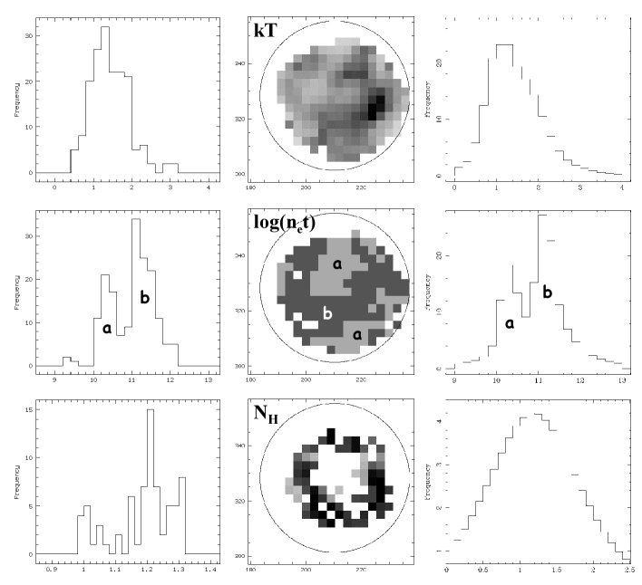
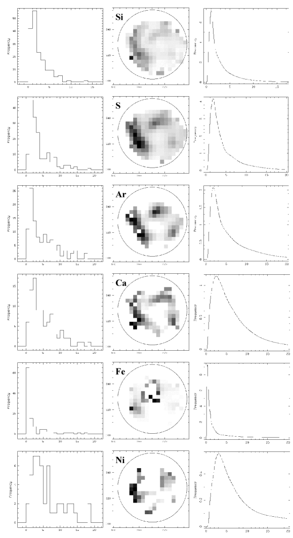
Results obtained fitting the 182 spectra with a NEI plasma model are listed in Table 4. They are also shown in Fig. 4 and in Fig. 5, where we present an histogram of the frequency distribution (left panels) and a map of the spatial distribution of the best fit values for each variable. In addition, we present in the right panel of Fig. 4 and Fig. 5 a frequency histogram of the same data used in the left panel, but where each single determination is transformed into a normalized gaussian with central value and as derived from the fits.
We note that in previous studies analyzing data from a variety of different instruments including BeppoSAX (Hill et al., (1975), from a rocket-borne proportional counter; Davison et al., (1976), experiment C on Ariel–5; Pravdo et al., (1976), proportional counter on OSO–8; Becker et al., (1979), SSS on Einstein; Jansen et al., (1988), EXOSAT; Holt et al., (1994), ASCA; Vink et al., (1996), ASCA; Favata et al., (1997), BeppoSAX), reasonable fits of the spatially unresolved spectrum of Cas A were obtained using two thermal models with different physical and chemical parameters, interpreted as an indication of the presence of two different components in the remnant. The only exception is given by the analysis of Tenma data (Tsunemi et al. 1986). In particular, BeppoSAX unresolved spectrum has been modeled with two NEI components respectively at the temperature of 1.25 and 3.8 keV. Our spatially resolved spectroscopic analysis allowed us to get statistically significant fits using only one thermal component per pixel with temperatures compatible with the one relative to the cooler component in Favata et al. (1997). This means that if two thermal components are indeed present, they are spatially separated.
5.1
values are distributed in the range 0.9–3.2 keV, with most of the values in the rather narrow 1–2 keV range. The distribution broadens slightly if we take into account the uncertainties on the derived values (Fig. 4, right panel). The shape of the continuum does not vary considerably across the remnant. We notice three exceptions: (i) a well defined minimum NE of centre with 0.9 keV, (ii) a maximum W of centre with 3 keV, correlated with the relative maximum in total emission indicated as ”C” in Fig. 2, and (iii) low values at the edge of the remnant (with the exception of the southern edge). A hot western component was also found by Vink et al. (1996) analyzing their ASCA data of Cas A.
It is well known from the physics of strong shocks through a gas with adiabatic index 5/3, that electron temperatures in the range 1–2 keV can be reached by post-shocked matter when the shock velocity is of the order of 900–1300 km s-1. From observations in the optical (Reed et al., (1995)) and in the X-rays (Holt et al., (1994); Vink et al., (1998)) we can infer that the main shock of Cas A is presumably running now more than 2 times faster, producing post-shock temperatures over 4 times higher than observed. Even in the hypothesis of a recent deceleration due to the interaction with a denser ISM, we should see in the map the signature of such a deceleration in the form of a substancial increase of at the edge(s) of the remnant. On the other hand, higher resolution X-ray images clearly show a strong surface brightness contrast between the main shock and the bright ring that dominates the X-ray and radio emission. Nowhere in our 182 locations across the remnant we detect high temperatures, strongly indicating that the main shock is now interacting with a very tenuous ISM, generating an emission that is too faint to be detected in our observations.
Although the morphology of the distribution of values is certainly of some importance, the real question to ask is: why do we detect a in the range 1–2 keV? A correlated question is: why do we see matter enriched in heavy elements ( through ) emitting in the X-rays at such temperatures? A similar question will be asked further on in a different context and for different reasons. What we know about the hydrodynamics of the explosion inside a star is rather well established: the shells of the exploding star closer to the mass-cut (e.g. the mass coordinate separating what will be ejected from the stellar remnant), carrying out the yield of explosive nucleosynthesis, reach extremely high temperatures fractions of a second after the beginning of the explosion inside the star. Few hours later, the main shock is still inside the star, at the base of the photosphere, ready to break through giving rise to the standard SuperNova event in the V and UV bands. At the same moment, those inner shells pulled out by the main shock have expanded almost to the surface of the star. But the key point is that they have already cooled down to temperatures lower than 0.01 keV.
If emission is dominated by the ejecta (but Borkowski et al., (1996) suggest a different interpretation), how to re-heat those ejected shells? The simplest answer can be found in Astrophysics textbooks and reviews (e.g.: McKee & Truelove, (1995)): ejected matter acts like a piston, a secondary shock forms, running back (in lagrangian coordinates) into the ejecta, re-heating it to temperatures lower than those produced by the main forward shock. We just note en passant that nobody thought of shifting the onset of secondary shocks to places where the probability of formation is certainly high (inside the star), and to the right time (hours before the SuperNova event).
Being this not the right place to question the applicability of this model to this particular case, we limit ourselves to suggest a different, more straightforward scenario, based on what we observe also in other wavelength ranges. The basic ingredients of our scenario are azimuthal secondary shocks to convert a small fraction of the bulk kinetic energy (erg) of ”polluted” shells into thermal energy. Only few % of kinetic energy need to be converted by azimuthal shocks into thermal energy to set up the scene for what we will observe 1010s later. Meanwhile, vorticity will help forming blobs or knots of frozen local composition and scrambling their relative positions.
The scenario is the following: at time (plus or minus hours, does not really matter) we deal with shells of material enriched in heavier elements that are rather cold. Energy is mostly in the form of kinetic energy. Their bulk motion is subsonic with respect to adjacent shells, but supersonic with respect to the value of the sound speed in the shells. This is a very unstable situation. Any element of matter with a random azimuthal velocity component will be shocked (or compressed) by radially moving adjacent matter. Kinetic energy will be transformed into thermal energy, and vorticity will set in. Of course the complexity of this basic scenario, based on azimuthal shocks in a cold supersonic flow, can be increased ad libitum adding rotation, and in general any non spherically symmetric effect.
5.2
Due to the limited extension towards low energies of the MECS well calibrated band (E1.6 keV) we cannot determine with reasonable accuracy. Taking into account the uncertainties in the determination of (see Fig. 4, right panel) we can say that our results are consistent with those of Kehoane et al. (1996). Moreover, we fitted one of the most significant spectra (namely, the spectrum marked with ”A” in Fig. 3, corresponding to the pixel X=203, Y=321 in Table 4) fixing to three different values; the results, as listed in Table 2, show that no significant variations in any of the sensitive spectral parameters are detected.
| (1022 cm-2) | 0.7 | 1.3 | 1.9 |
|---|---|---|---|
| kT (keV) | 1.60.26 | 1.460.29 | 1.40.22 |
| log()(cm-3s) | 11.250.2 | 11.30.22 | 11.30.2 |
| [] | 5.91.35 | 6.461.72 | 82 |
5.3
The ionisation parameter controls the non equilibrium ionisation status of the emitting plasma. Because we express in units of cm-3s and its value can vary by orders of magnitude, in Table 4, in Fig. 4 and in this discussion we will always refer to values of . For the elements considered in this paper ( through ) a low value of the ionisation parameter (e.g. ) indicates an ionisation structure far from equilibrium, while the structure is practically in equilibrium for values greater than 12. In the fitting procedure is allowed to vary in the range 6–12.5.
The frequency distribution of values is clearly bimodal, with lower boundaries at about 10 and 11. Because an upper limit for is the age of the remnant (assumed to be 320 y, e.g. =10 in our units), this can give us a good handle in understanding the density distribution within the remnant. The simplest hypotheses concerning the density distribution are:
case (i): we fix to infer the distribution of . We are observing matter shocked (once or more than once) 1010s ago, that is during the early phases of the explosion. Then the distribution of the ionisation parameter actually reflects the distribution of the electron density, shifted by 10 orders of magnitude. If this hypothesis is true, we detected a bimodal density distribution, with a first component (marked in Fig. 4) with in the range 1–10 cm-3 and a second component (marked in the same Figure) about 10 times denser. All in all (actually: the electron density averaged over our pixel volume) would cover the range 1–100.
case (ii): we fix the distribution of to infer the distribution of (e.g. of the main shocking episodes). The sharp boundary at =11 indicates that in the remnant is present only one component () with (pixel averaged) in the range 10–100 cm-3 and over that was shocked 1010s ago. From the boundary at = 10 we can infer that a consistent fraction of this same matter (with 10 cm-3) was suddenly re-shocked 1010 cm/10 cm-3 = 109s 32 y ago (that is in the mid sixties, when Cas A was already well observed). There could have been two different causes for this sudden re-shocking of part of the remnant: external, e.g. matter at the edge of the remnant hit pre-existing clouds or condensation; internal, e.g. blobs or fingers of material inside the remnant collided and re-heated. What we observe in Fig. 4 is that this hypothetically re-shocked material is located mostly at the centre of the remnant and north of it, with few other pixels at the edges. But no particular anomalies in are found at the corresponding locations that could be interpreted as signatures of a very recent re-shocking.
These first two cases are the extreme possibilities in which we fix either or .
(iii) a third intermediate possibility is that matter is distributed in components and as in (i), plus an additional component of density higher than component by a factor , that was then re-heated years ago. Factor must be significantly greater than 1 in order to consider this case different from case (i).
The above hypotheses have an obvious impact on the determination of the total mass of the remnant: can be up to 4 times , and .
We favour hypothesis (i) on the basis of the following considerations:
(1) case (i) is not in contrast with the other results of our analysis. On the other hand we don’t see evidence for the re-heating implied by cases (ii) and (iii).
(2) the observed values of are much too low to indicate the presence of shocked ISM (i.e. matter not ejected by the progenitor star in its pre-SN life). These values imply that what we are observing is just matter belonging to the progenitor star spread out in a volume of about 3 pc in radius.
(3) the lowest possible total mass of the (X-ray) emitting gas computed according to hypothesis (i) is already in the range 13–30 M⊙, reasonable masses for the progenitor star. By the way, X-ray emitting masses in this range were already suggested by Murray et al. (1979) and Fabian et al. (1980).
Combining the two last considerations, one sees that no much room is left for hypothesis like (ii) or (iii), that will lead to total masses exceedingly large for the progenitor star.
If we then retain only hypothesis (i), component could be associated to the CSM, and the denser component to the disrupted star. We should then detect a correlation between the spatial distribution of component and that of overabundances. Anticipating the results of the discussion of Fig. 5, we can say that this hypothesis is not in contradiction with the maps of abundance values shown in Fig. 5, with the only exception of the northern sector of the remnant.
Another interesting consequence concerns the ratio by mass of these two components. Although components and are spread over 40% and 60% of the pixels, respectively, the mass ratio is . This ratio is much smaller than in previous estimates (see Vink et al., (1996), Borkowski et al., (1996)). In other words, our results seem to suggest that the progenitor star lost in its pre-SN phase a small fraction of its mass. If Cas A was an underluminous SN event, it wasn’t because it lost most of its envelope before the explosion. Other explanations should be found: a moderate initial mass or a high mass-cut at the moment of the explosion, if component represents the total CSM mass, or, alternatively, we are detecting only a fraction of the total CSM, which is actually distributed over a much larger volume than the remnant. This would be the case if much of the mass loss occurred when the progenitor was a blue supergiant.
We also remark that the denser component is not distributed in our map (in Fig. 4) as it should if matter had been ejected in spherical symmetry. On the contrary, the shape of the distribution of component in Fig. 4 could support the hypothesis of a toroidal ejection with an axis of symmetry oriented from NE to SW. Markert et al. (1983) were the first to notice from X-ray spectra of Cas A, taken with the crystal spectrometer on board the Einstein Observatory, that the northwest part of Cas A is red-shifted with respect to the southeast, with a dividing line running then from NE to SW. The same symmetry was found by Holt et al. (1994) in their ASCA data, from which they could build a Doppler contour map of Cas A showing that the SE part of the remnant was blue-shifted and the NW region was red-shifted. The torus could be by now broken in a number of different concentrations, giving rise to the SE emission enhancement (running towards us) and other in the north and west (running away from us).
5.4 Abundances
Abundances were derived, with varying degree of accuracy, for in 167 out of the 182 pixels, for in 164 pixels, for in 106 pixels, for in 90 pixels, for in 105 pixels, and for in 49 pixels. The determination of and abundances is affected by the position of the corresponding blends at the opposite extremes of our energy window. The fit of the blend is affected by the unability to constrain reasonably well the value of , while the blend is located in a region of the spectrum where the count rate is the lowest, although the presence of a line is not related to the statistics of the spectrum: see spectra A and B in Fig. 3. The list of elements in order of decreasing global accuracy of the corresponding abundance determination is: , , , , , and .
The frequency distributions of abundance determination (with respect to solar, by number) are shown in the left panels of Fig. 5. The right panels map the spatial distribution of these values, with the same intensity scale for all six panels. The same reference circle centered at the expansion centre (as defined by Reed et al., (1995)) is shown in all panels for sake of comparison of the different distributions.
Now, we know that Cas A is located not much further away from the centre of the Galaxy than our Sun, and was generated by the explosion of a massive star born between about 3 to 10 My ago. In terms of the time scale of galactic evolution, this means ”now”, and today’s abundances of the ISM at the location of Cas A are basically solar. On all this there is a general consensus. As well as on the obvious expectation to detect overabundances of heavy elements (in our case: to ) with respect to solar values, as found in the optical knots.
But from common knowledge (certainly still limited) of explosive nucleosynthesis the following question is fully justified: should we really expect to observe those overabundances? The answer is: yes, for -elements, and: not necessarily, for and . Suppose the extreme hypothesis of a complete mixing, above the mass-cut, of all the matter belonging to the progenitor star. The production of -elements is such that, unless stellar matter is diluted in a much greater mass of ISM, we do expect to observe overabundances of through . On the other hand, depending on the precise value of the mass-cut, overabundances of and could well pass undetected.
A more likely scenario, based on high spatial resolution studies of this remnant in the optical (and now also in the X-rays), is that Cas A is a remnant composed by scrambled ”blobs” or knots of frozen local material more than a mixed distribution of matter. In this case we should re-formulate our answer to the previous question, saying that: yes, we do expect overabundances of heavy elements, but only in the location of parcels or blobs of ejecta keeping trace of the effects of explosive nucleosynthesis. In other locations we can only expect to find abundances that will reflect those of the ISM at the time the progenitor star was born. Actually, due to s-process nucleosynthesis, the abundance could even be depleted below its initial value (see for instance the recent paper by Limongi et al., (2000)).
From the left panels of Fig. 5 we clearly see that in the majority of the pixels we are detecting abundance values compatible with solar values. More in detail, there seems to be indications that in the location of Cas A abundances of and are somewhat below solar, while abundances of the -elements are above solar. As an example, for we find that about 2/3 of the pixels show an average abundance 1/2 solar, and for the average abundance is 1.7 solar in 40% of the pixels. For comparison, Borkowski et al. (1996) derived for the CSM component abundances 0.4solar for and , and slightly below solar for other elements heavier than .
On the other hand we do see overabundances in particular locations inside the remnant that lead to global overabundances. From the results listed in Table 4 we can compute for each element the ratio [X] between the mass fraction per unit solar mass of element X and the mass fraction of the same element in the sun. We can compute this overabundance by mass in two different assumptions: (1) we can consider only pixels in which we detect the element, or (2) we can consider also the contribution of all the other pixels where we assume that abundances are solar (i.e. were not altered by nucleosynthesis in the progenitor star). The global overabundance factors we find according with these two assumptions are listed in Table 3.
| Element | (1) | (2) |
|---|---|---|
| [] | 3.3 | 3.1 |
| [] | 5.3 | 5.0 |
| [] | 6.3 | 4.1 |
| [] | 6.8 | 4.6 |
| [] | 1.5 | 1.4 |
| [] | 7.1 | 3.9 |
As we can see from the right panels of Fig. 5, all the elements are particularly overabundant in the south-east. This region is extending up to the east in , , , and maps. At lower level of overabundance these four elements trace a sort of broken shell, more evident in the case of and maps; similar results were found by Holt et al. (1994) and Hwang et al. (2000).
6 Conclusions
We have performed the first detailed spatially resolved spectroscopy of Cas A in the X-rays, using data taken with the MECS spectrometer on board the BeppoSAX Observatory. The extremely well calibrated PSF in the central region of the MECS allowed us to perform a spatial deconvolution of our data at full energy resolution. We eventually generated a data cube consisting of 182 spectra, each one referring to a squared pixel of 24 in size, covering a region of 3 radius around the centre of Cas A.
We performed a fit of the 182 spectra using as models a NEI plasma and a power law with fixed normalization and index to account for the high energy tail observed by BeppoSAX. Statistical errors on counts have been modified to take into account the systematic effects of the deconvolution procedure.
In a previous study, reasonable fits of the spatially unresolved spectrum of Cas A observed by BeppoSAX were obtained using two thermal models with different physical and chemical parameters, indicating the presence of two different components in the remnant. On the contrary, spatially resolved spectroscopy allowed us to get statistically significant fits using only one thermal component per pixel. This means that if two thermal components are indeed present, they are spatially separated.
We found a rather uniformly distributed , with a minimum in the east, a maximum in the west, and most of the values in the range 1–2 keV. No evidence is found for high expected from the interaction of the main shock with the ISM. No anomalies in the distribution are found at the edge of the remnant. We interpret this as an indication that we are detecting only matter belonging to the progenitor star.
We have then discussed how to re-heat matter to the observed values, in particular matter enriched by heavier elements, that is expected to have already cooled down to 0.01 keV at the moment of the SN event. A possibility is to invoke the standard ”reverse shock” model. In this paper we have also suggested a scenario based on azimuthal secondary shocks in the supersonic flow generated by the main shock inside the star. Only a small fraction of the kinetic energy needs to be converted into thermal energy by azimuthal shocks. The peculiarity of this scenario is that azimuthal shock can be formed from hours before to years after the SN event. Actually they could still be at work now. Observations in the X-rays at much higher spatial resolution could help in clarifying the issue.
From the discussion of our results on the ionisation parameter we infer that two distinct components there exist: the first with in the range 1–10 cm-3, the second with ten times (or more) higher. The first component (called ) can be associated with matter ejected by the star before the SN event, while the denser component (), not spherically symmetric, can be associated with matter ejected during the explosion. An important consequence of this interpretation is that the mass ratio is 1/10, indicating a progenitor star of moderate mass that lost only a small fraction of the envelope during its pre-SN life.
We also interpret the distribution of component across the remnant as an indication that the explosion was not spherically symmetric, possibly toroidal.
The distribution of abundances indicates that we are detecting a CSM component with almost solar composition, and an ejecta component enriched in heavier elements. Abundances found for –elements are consistent with the current view that Cas A was produced by the explosion of a massive star. But, as already suggested by Vink et al. (1996), low overabundances can be an indication that at the moment of the explosion the mass-cut was rather high, locking most of the produced 56 into the stellar remnant. The value of abundance found in the CSM component (less than the solar one) is again in agreement with theoretical predictions.
Acknowledgements.
We thank J.Vink and B.Sacco for a critical reading of the manuscript and for useful comments. This work was supported by ASI contract ARS–99–15.| X | Y | ||||||||||
|---|---|---|---|---|---|---|---|---|---|---|---|
| 191 | 321 | 0.85(21) | |||||||||
| 191 | 324 | 11.55.43 | 1.08(35) | ||||||||
| 191 | 327 | 1.09: | 0.750.23 | 10.40.35 | 0.920.69 | 1.861.52 | 1.50: | 1.05(48) | |||
| 191 | 330 | 1.23: | 1.010.37 | 10.20.27 | 1.811.35 | 5.283.60 | 7.82: | 1.00(48) | |||
| 191 | 333 | 1.31: | 1.040.52 | 10.30.32 | 1.891.60 | 8.267.48 | 13.2: | 1.00(45) | |||
| 191 | 336 | 0.830.52 | 10.40.47 | 1.26: | 8.24: | 5.39: | 1.19(30) | ||||
| 194 | 315 | 0.82(17) | |||||||||
| 194 | 318 | 1.611.06 | 11.30.61 | 13.511.9 | 8.115.45 | 15.4: | 2.282.24 | 1.00(48) | |||
| 194 | 321 | 0.630.10 | 11.61.33 | 1.301.03 | 3.322.52 | 13.5: | 1.23(73) | ||||
| 194 | 324 | 1.020.99 | 0.990.27 | 11.80.88 | 3.622.71 | 6.434.12 | 1.75: | 18.6: | 1.55(91) | ||
| 194 | 327 | 1.000.99 | 1.220.44 | 11.60.59 | 4.812.82 | 8.934.22 | 9.506.69 | 3.56: | 0.89: | 13.3: | 1.49(91) |
| 194 | 330 | 1.30: | 1.280.60 | 11.50.70 | 5.773.64 | 10.75.35 | 17.711.0 | 4.90: | 0.47: | 10.8: | 1.23(89) |
| 194 | 333 | 1.350.71 | 11.50.74 | 7.143.87 | 12.23.06 | 11.76.97 | 0.59: | 1.06(76) | |||
| 194 | 336 | 1.22: | 1.090.45 | 10.50.29 | 1.020.58 | 5.973.03 | 6.05: | 3.54: | 2.85: | 1.16(57) | |
| 194 | 339 | 1.170.82 | 11.74.07 | 0.77(32) | |||||||
| 197 | 312 | 0.500.41 | 11.23.68 | 0.92(22) | |||||||
| 197 | 315 | 0.850.18 | 12.23.73 | 4.333.76 | 6.195.12 | 16.8: | 1.71: | 0.83(61) | |||
| 197 | 318 | 1.01: | 0.870.11 | 3.441.55 | 6.742.98 | 12.29.01 | 4.201.57 | 14.3: | 1.12(95) | ||
| 197 | 321 | 1.020.56 | 1.110.24 | 11.70.50 | 7.045.27 | 13.39.32 | 8.357.72 | 6.54: | 12.1: | 1.52(113) | |
| 197 | 324 | 1.000.94 | 1.210.28 | 11.50.39 | 6.553.25 | 12.95.76 | 9.375.89 | 12.58.43 | 4.543.26 | 11.5: | 1.72(114) |
| 197 | 327 | 1.190.66 | 1.270.34 | 11.40.39 | 7.493.42 | 14.75.76 | 14.17.31 | 11.87.77 | 2.641.72 | 18.816.9 | 1.19(114) |
| 197 | 330 | 1.220.70 | 1.170.32 | 11.60.54 | 6.303.40 | 11.95.57 | 14.28.36 | 9.627.58 | 1.611.40 | 13.6: | 0.91(108) |
| 197 | 333 | 1.200.95 | 1.080.11 | 4.612.33 | 7.683.72 | 8.215.58 | 1.120.75 | 0.66(94) | |||
| 197 | 336 | 1.151.06 | 1.280.40 | 11.91.24 | 6.226.10 | 8.857.02 | 7.947.56 | 10.5: | 1.02: | 0.77(79) | |
| 197 | 339 | 1.04: | 1.881.12 | 11.40.62 | 7.116.30 | 7.564.90 | 5.28: | 7.67: | 0.61: | 0.54(55) | |
| 197 | 342 | 1.110.65 | 11.71.41 | 1.83: | 2.40: | 0.80(22) | |||||
| 200 | 309 | 0.91: | 11.22.53 | 1.09(17) | |||||||
| 200 | 312 | 1.07: | 1.300.84 | 11.30.76 | 5.094.15 | 4.732.48 | 0.49: | 0.93(55) | |||
| 200 | 315 | 1.200.90 | 0.930.11 | 3.721.87 | 6.603.07 | 6.494.97 | 1.56: | 0.98(94) | |||
| 200 | 318 | 1.160.52 | 1.120.22 | 11.80.57 | 7.615.22 | 14.99.63 | 17.412.9 | 8.677.88 | 4.694.67 | 7.23: | 1.43(116) |
| 200 | 321 | 1.160.00 | 1.310.24 | 11.40.31 | 9.183.83 | 18.87.58 | 18.29.64 | 5.123.33 | 9.89: | 1.75(127) | |
| 200 | 324 | 1.180.57 | 1.180.24 | 11.40.29 | 5.311.64 | 11.93.01 | 10.43.91 | 10.45.00 | 2.431.01 | 3.48: | 1.49(127) |
| 200 | 327 | 1.210.67 | 0.950.18 | 11.60.38 | 3.731.26 | 9.272.77 | 9.284.28 | 7.044.71 | 1.680.97 | 1.19(121) | |
| 200 | 330 | 1.260.73 | 0.890.17 | 11.80.63 | 3.371.37 | 7.652.84 | 7.454.37 | 3.87: | 1.190.94 | 0.95(116) | |
| 200 | 333 | 1.230.72 | 0.990.19 | 11.91.01 | 3.401.66 | 5.982.48 | 5.243.51 | 3.60: | 0.75: | 6.81: | 0.84(110) |
| 200 | 336 | 1.060.76 | 1.280.28 | 11.80.57 | 3.261.52 | 3.941.33 | 2.19: | 3.00: | 0.53: | 6.65: | 0.78(97) |
| 200 | 339 | 1.151.12 | 1.490.46 | 11.60.50 | 3.201.71 | 2.591.12 | 0.41: | 4.57: | 0.73(81) | ||
| 200 | 342 | 1.531.08 | 11.50.87 | 3.333.15 | 1.85: | 7.37: | 12.7: | 1.01(45) | |||
| 203 | 309 | 1.521.44 | 10.60.83 | 3.04: | 2.091.87 | 0.97(37) | |||||
| 203 | 312 | 1.20: | 1.620.67 | 11.10.36 | 4.422.36 | 4.871.66 | 7.283.70 | 0.360.35 | 0.90(77) | ||
| 203 | 315 | 1.260.66 | 1.010.08 | 4.481.79 | 8.122.85 | 11.85.55 | 1.370.59 | 1.07(110) | |||
| 203 | 318 | 1.300.64 | 1.180.21 | 11.70.40 | 5.862.27 | 11.73.93 | 14.35.98 | 6.434.28 | 2.121.30 | 2.98: | 1.42(125) |
| 203 | 321 | 1.300.61 | 1.460.29 | 11.30.22 | 6.461.72 | 12.02.45 | 11.83.39 | 9.433.94 | 1.670.51 | 4.693.59 | 1.45(128) |
| 203 | 324 | 1.280.64 | 1.400.30 | 11.20.21 | 4.561.13 | 8.511.70 | 6.512.29 | 6.553.23 | 0.760.23 | 4.523.40 | 1.21(125) |
| 203 | 327 | 1.20: | 1.010.18 | 10.40.11 | 1.430.66 | 3.920.85 | 2.331.11 | 0.46: | 6.695.29 | 0.91(118) | |
| 203 | 330 | 1.20: | 0.860.16 | 10.60.13 | 1.200.75 | 3.421.00 | 1.990.99 | 0.61: | 7.50: | 0.88(110) | |
| 203 | 333 | 1.200.54 | 0.860.09 | 10.60.13 | 0.900.19 | 2.580.46 | 1.080.75 | 0.750.69 | 8.207.95 | 1.02(109) | |
| 203 | 336 | 1.020.68 | 1.240.22 | 11.50.26 | 2.070.58 | 2.890.70 | 2.25: | 0.390.26 | 6.544.45 | 0.93(106) | |
| 203 | 339 | 1.190.81 | 1.540.29 | 11.40.22 | 2.300.77 | 1.950.50 | 1.21: | 0.26: | 0.94(94) | ||
| 203 | 342 | 1.670.63 | 11.40.38 | 2.611.42 | 1.430.74 | 2.97: | 1.02(62) | ||||
| 203 | 345 | 1.271.14 | 11.41.23 | 2.19: | 1.05(23) | ||||||
| 206 | 309 | 3.97: | 10.60.30 | 5.044.40 | 3.561.68 | 5.114.37 | 10.1: | 0.67(53) | |||
| 206 | 312 | 1.201.20 | 1.990.78 | 11.10.25 | 3.761.72 | 4.591.56 | 5.973.16 | 0.20: | 0.85(93) | ||
| 206 | 315 | 1.301.21 | 2.000.42 | 11.10.15 | 4.811.54 | 7.521.66 | 9.322.77 | 4.352.84 | 0.250.22 | 1.15(112) | |
| 206 | 318 | 1.820.30 | 11.20.13 | 5.541.61 | 8.161.53 | 7.562.14 | 5.432.53 | 0.400.19 | 1.29(122) | ||
| 206 | 321 | 1.220.57 | 1.840.33 | 11.10.14 | 4.060.97 | 6.071.07 | 4.221.59 | 4.262.23 | 0.400.18 | 1.34(125) | |
| 206 | 324 | 1.120.61 | 1.490.25 | 11.10.15 | 2.470.58 | 3.890.72 | 1.441.21 | 2.031.87 | 0.250.13 | 3.272.32 | 1.07(123) |
| 206 | 327 | 1.00: | 1.130.12 | 10.30.10 | 1.300.30 | 2.700.44 | 1.100.68 | 5.074.73 | 1.02(113) | ||
| 206 | 330 | 1.00: | 0.950.11 | 10.30.10 | 1.660.53 | 3.280.80 | 1.680.96 | 0.79: | 0.98(111) | ||
| 206 | 333 | 1.00: | 0.910.10 | 10.40.10 | 1.360.26 | 3.450.66 | 1.740.97 | 1.630.89 | 1.02(114) | ||
| 206 | 336 | 1.050.21 | 10.30.12 | 1.150.81 | 3.221.21 | 0.970.93 | 1.781.08 | 0.95(112) | |||
| 206 | 339 | 1.220.00 | 1.240.10 | 10.30.14 | 0.860.27 | 2.110.54 | 0.55: | 5.54: | 1.02(101) | ||
| 206 | 342 | 1.190.98 | 1.320.26 | 11.50.30 | 2.140.90 | 1.980.63 | 1.06(75) | ||||
| 206 | 345 | 1.19: | 0.830.25 | 12.14.25 | 1.481.46 | 0.66: | 0.69: | 0.95(38) |
Table 4 - continued
X
Y
209
306
1.390.70
11.21.06
1.23:
1.00(23)
209
309
1.560.66
10.90.48
1.000.59
1.240.68
9.47:
0.75(62)
209
312
1.291.16
1.560.35
11.30.23
1.570.58
2.080.55
1.00:
0.12:
1.34:
0.77(93)
209
315
1.38:
1.680.35
11.30.19
2.630.73
3.480.78
3.921.75
2.292.14
0.14:
0.94(111)
209
318
1.301.04
1.980.33
11.20.12
3.210.83
3.990.77
3.931.53
3.932.09
0.16:
0.92(116)
209
321
1.050.53
1.720.24
11.30.12
2.150.48
2.450.48
1.361.10
1.40:
0.180.15
0.81(120)
209
324
1.570.20
11.10.14
1.460.31
1.700.27
0.11:
1.54:
0.85(119)
209
327
1.360.16
10.50.18
0.970.17
1.700.29
0.50:
1.00(115)
209
330
1.180.10
10.10.09
2.120.70
3.080.70
1.560.82
17.7:
1.11(119)
209
333
1.390.19
10.10.07
2.980.72
6.031.28
4.882.21
2.621.94
1.11(119)
209
336
1.350.19
10.30.07
2.200.48
6.281.16
5.152.22
4.572.18
1.08(119)
209
339
1.20:
1.130.21
10.30.11
1.300.82
3.991.53
2.281.14
2.331.25
1.05(112)
209
342
1.301.07
1.050.14
10.30.16
0.710.27
1.940.46
0.880.84
2.64:
1.03(88)
209
345
1.301.06
0.770.16
10.40.29
0.750.43
0.970.55
1.08(48)
212
306
1.510.88
10.01.26
0.97(30)
212
309
1.550.34
10.20.79
0.40:
0.63:
0.74(68)
212
312
1.450.26
11.30.26
0.840.37
1.270.38
2.942.19
0.12:
4.913.01
0.80(94)
212
315
1.300.91
1.700.34
11.30.18
1.500.46
1.950.53
1.831.41
2.362.03
0.18:
2.362.14
0.87(113)
212
318
1.200.64
1.960.36
11.20.14
1.850.49
2.080.48
2.091.28
1.871.75
0.79(120)
212
321
1.780.22
11.30.12
1.370.33
1.200.27
0.57:
0.62(117)
212
324
1.000.82
1.670.24
11.20.14
1.190.29
1.010.25
0.08:
1.771.50
0.56(112)
212
327
1.00:
1.240.13
10.10.17
1.060.59
1.210.40
15.4:
0.80(116)
212
330
1.290.11
10.10.12
1.440.57
2.390.66
1.930.87
0.95(119)
212
333
1.680.21
10.10.06
2.660.56
5.991.08
7.702.73
1.26:
1.17(123)
212
336
1.01:
1.770.44
10.20.09
3.391.13
9.462.06
13.24.86
6.563.72
1.47(124)
212
339
1.201.17
1.290.27
10.30.10
1.830.83
6.241.52
6.432.45
3.991.99
1.30(122)
212
342
1.31:
1.020.12
10.30.11
0.850.25
2.830.60
2.171.08
7.487.26
1.03(96)
212
345
0.740.11
10.40.21
0.880.41
1.370.53
1.34(59)
212
348
0.580.07
11.8:
0.80(22)
215
306
1.641.06
9.220.69
5.26:
0.53(27)
215
309
1.00:
1.470.37
10.60.35
0.23:
0.45:
3.692.64
0.65(66)
215
312
1.230.87
1.650.37
10.70.39
0.360.23
0.940.36
4.073.35
0.73(90)
215
315
1.220.52
1.770.25
10.40.30
0.380.18
1.050.27
0.69:
1.861.40
0.93(113)
215
318
1.31:
1.960.34
11.20.14
1.180.34
1.270.34
0.83:
1.42:
0.85(121)
215
321
1.930.28
11.30.13
1.110.29
0.910.26
0.79(120)
215
324
1.720.25
11.30.14
0.940.25
0.750.25
0.09:
0.66(119)
215
327
1.280.09
10.20.19
0.560.41
0.880.32
12.6:
0.75(120)
215
330
1.170.17
11.00.22
0.610.13
1.390.25
1.760.96
0.660.32
0.92(126)
215
333
1.480.12
10.30.10
1.210.22
3.410.54
4.441.13
11.89.10
1.15(128)
215
336
1.00:
2.280.45
10.40.07
3.100.71
7.841.15
11.82.84
7.743.16
5.841.96
1.34(131)
215
339
1.200.71
1.830.36
10.40.09
2.360.60
6.981.10
9.722.65
7.073.10
4.501.96
1.45(125)
215
342
1.210.64
1.250.19
10.40.12
1.100.24
3.800.71
3.311.59
1.031.00
2.422.16
1.01(109)
215
345
0.810.12
10.30.18
0.920.36
1.820.55
0.94(68)
215
348
0.580.38
11.5:
0.90(23)
218
306
1.661.42
9.380.48
5.04:
5.27:
0.53(25)
218
309
1.10:
1.430.45
9.600.33
2.04:
1.58:
0.73(55)
218
312
1.210.74
1.740.33
10.20.42
0.390.33
1.060.55
1.15:
0.75(89)
218
315
1.31:
1.900.36
10.30.34
0.380.24
1.040.29
0.83:
0.82(106)
218
318
2.140.29
11.10.13
1.050.32
1.300.27
0.83:
1.08:
0.79(117)
218
321
1.190.49
2.230.28
11.20.11
1.220.32
1.270.26
0.52:
0.88(127)
218
324
1.880.22
11.30.12
0.860.23
0.910.22
0.140.14
0.92(127)
218
327
1.00:
1.500.19
11.20.15
0.640.20
0.990.22
0.79:
0.230.12
2.341.42
0.96(129)
218
330
1.000.75
1.320.16
11.20.16
0.730.19
1.510.27
1.920.87
0.540.13
6.552.85
1.02(133)
218
333
1.550.21
11.00.12
1.230.23
2.860.39
3.550.99
1.020.12
6.552.67
1.07(137)
218
336
1.00:
2.250.41
10.80.10
2.780.60
6.080.94
6.581.61
5.002.03
1.820.35
6.952.94
1.09(137)
218
339
1.280.58
1.880.36
10.90.13
3.060.77
6.381.17
6.161.85
8.052.77
1.270.25
3.472.46
1.35(131)
218
342
1.270.80
1.670.41
11.10.20
2.920.91
4.961.22
2.791.90
5.133.15
0.270.19
3.533.06
1.21(106)
218
345
1.16:
1.330.41
11.30.38
3.201.76
3.251.12
0.93(62)
218
348
0.610.36
10.61.83
0.76(19)
221
309
1.380.55
10.10.58
1.65:
1.81:
0.62(44)
221
312
1.210.86
1.590.36
10.40.38
0.450.28
1.380.53
0.80(76)
221
315
1.230.79
1.730.38
10.90.29
0.600.34
1.550.49
2.481.54
1.01:
0.11:
0.73(97)
221
318
2.050.31
11.10.13
1.090.34
1.790.40
2.241.13
0.150.14
0.88(115)
221
321
1.200.51
2.480.40
11.10.11
1.310.33
1.950.36
1.580.95
0.250.17
0.92(132)
221
324
1.200.00
2.200.18
11.20.10
1.110.25
1.620.29
0.960.75
1.06:
0.360.15
0.96(138)
221
327
1.040.43
1.900.24
11.20.11
0.860.21
1.540.28
0.890.84
0.95:
0.350.15
0.88:
1.09(138)
221
330
1.040.37
1.780.21
11.20.11
0.980.20
1.840.26
1.290.70
0.420.13
2.611.25
1.05(138)
221
333
1.020.43
1.860.27
11.10.11
1.530.30
2.850.45
2.430.99
0.590.15
3.591.51
1.25(136)
221
336
1.000.60
2.270.44
11.00.11
2.910.64
5.110.86
5.061.54
5.162.10
0.930.21
4.792.01
1.29(136)
221
339
1.160.65
2.020.46
11.00.15
3.511.00
5.401.17
4.711.98
7.653.08
0.830.25
3.352.32
1.29(120)
221
342
1.04:
1.810.65
11.10.26
2.961.24
3.961.31
2.87:
0.21:
1.41(91)
221
345
1.921.22
10.90.43
4.734.05
3.812.07
7.10:
1.01(47)
Table 4 - continued
X
Y
224
309
1.490.87
11.10.77
1.221.10
1.851.30
0.44:
0.37(31)
224
312
1.27:
1.240.45
11.10.64
0.650.46
1.470.74
0.61(56)
224
315
1.31:
1.210.19
10.10.20
0.680.60
1.850.85
2.681.84
0.80(83)
224
318
1.300.80
1.810.32
11.20.16
1.340.43
3.090.70
5.551.86
4.422.35
0.240.18
1.19(109)
224
321
1.200.50
3.160.63
11.00.10
1.990.50
4.040.64
5.341.41
6.121.95
0.610.20
1.18(135)
224
324
1.200.41
3.070.50
11.00.08
1.550.34
3.150.45
3.050.97
4.391.46
0.730.18
1.22(143)
224
327
1.290.42
2.530.33
11.00.09
1.120.24
2.280.32
1.780.76
3.001.20
0.410.14
0.89:
1.11(143)
224
330
1.280.42
2.110.27
11.10.10
1.160.24
2.040.32
1.060.75
1.721.16
0.320.13
2.211.20
1.04(138)
224
333
1.160.50
1.770.27
11.30.13
1.610.36
2.510.47
1.611.04
2.941.61
0.370.18
3.141.63
1.21(129)
224
336
1.00:
1.500.30
11.40.23
2.250.62
3.660.86
2.721.73
6.222.95
0.680.33
4.302.85
1.16(116)
224
339
1.390.41
11.50.37
2.931.17
4.271.46
2.48:
8.715.29
0.960.57
8.616.85
0.88(97)
224
342
1.141.14
1.120.29
10.30.30
1.000.60
2.010.74
1.50:
0.89(62)
224
345
1.611.29
10.60.75
2.13:
2.121.83
7.12:
0.62(24)
227
312
0.870.38
11.21.77
0.80:
1.301.21
0.46(38)
227
315
1.221.01
0.990.21
10.80.89
0.500.34
1.610.72
1.29:
0.78(64)
227
318
1.230.88
1.070.23
11.90.97
1.430.73
3.781.41
7.773.97
10.15.78
0.47:
5.07:
1.09(97)
227
321
1.290.61
2.080.45
11.20.15
1.870.54
4.871.05
8.572.36
10.33.14
0.970.29
2.762.19
1.36(126)
227
324
1.300.70
2.890.47
11.00.09
1.340.33
3.670.55
5.121.23
6.041.72
0.910.20
1.38(137)
227
327
1.300.42
2.990.44
10.90.09
0.930.24
2.450.34
2.510.82
2.861.21
0.380.13
1.12(137)
227
330
1.250.51
2.280.35
11.10.11
1.020.27
2.010.36
1.400.89
2.171.38
0.130.13
0.87(130)
227
333
1.120.71
1.480.27
11.50.22
1.350.44
2.030.56
1.551.43
3.452.28
0.290.25
2.522.24
0.95(107)
227
336
1.071.04
1.040.23
12.11.35
1.420.90
2.221.07
4.23:
0.68:
5.77:
1.06(85)
227
339
1.171.01
0.810.19
10.60.29
0.570.34
1.670.68
2.041.73
0.78(58)
227
342
0.680.57
11.64.03
0.60(28)
230
312
0.65:
10.81.95
0.62(16)
230
315
1.200.00
0.710.12
1.370.72
1.941.10
5.61:
0.52(40)
230
318
1.220.92
0.940.19
10.80.60
0.580.28
2.230.78
1.92:
1.26:
0.95(69)
230
321
1.200.16
10.20.08
0.670.24
2.980.69
4.011.84
2.401.45
1.16(102)
230
324
1.210.45
1.880.25
10.40.18
0.400.16
2.120.34
4.581.41
2.871.55
1.201.16
1.14(117)
230
327
1.33:
1.810.30
11.20.16
0.710.30
1.910.45
3.151.36
2.411.76
0.280.19
0.92(115)
230
330
1.200.00
1.810.25
11.20.19
0.990.36
1.770.44
2.821.27
0.14:
0.87(100)
230
333
1.460.42
11.50.34
1.430.76
1.610.81
1.98:
0.30:
0.95(73)
230
336
1.180.60
11.70.97
1.951.71
1.591.40
0.66:
0.81(44)
230
339
1.661.56
11.40.85
5.55:
3.87:
1.73:
0.52(20)
233
315
0.500.49
11.01.80
2.20:
0.72(18)
233
318
1.200.00
0.550.32
1.28:
2.78:
0.86(40)
233
321
0.920.25
12.22.95
1.210.97
2.631.31
0.68:
0.93(63)
233
324
1.20:
1.130.33
10.20.21
0.56:
2.341.87
1.32:
1.11(78)
233
327
1.280.37
11.40.39
0.750.54
2.131.02
3.263.00
0.93(71)
233
330
1.19:
1.270.59
11.50.63
1.491.12
2.361.31
3.64:
0.27:
0.92(57)
233
333
1.291.09
11.40.93
1.89:
1.83:
0.70(32)
236
318
0.88(13)
236
321
0.82(24)
236
324
0.870.33
10.40.45
0.63:
2.111.30
0.78(33)
236
327
0.800.36
12.04.44
0.92:
2.66:
0.73(28)
236
330
1.161.12
11.82.10
2.71:
2.80:
0.57(16)
236
318
0.88(13)
236
321
0.82(24)
236
324
0.870.33
10.40.45
0.63:
2.111.30
0.78(33)
236
327
0.800.36
12.04.44
0.92:
2.66:
0.73(28)
236
330
1.161.12
11.82.10
2.71:
2.80:
0.57(16)
Legenda:
X and Y are given in sky pixels (unit step 8 arcsec).
is in units of 1022 atoms cm-2.
is in keV.
is in units of cm-3s.
Column marked , , ,
, , and list abundance ratios with respect
to reference values (solar abundances by number).
Reference values used in the fitting model are (H=1):
, ,
, ,
, .
Quoted errors are one standard deviation.
A value followed by a semicolon indicates a large uncertainty.
A dash replaces values that was impossible to constrain to a
statistically significant level.
Appendix A Error Treatment
Errors associated to the counts in each pixel of the final images are the combination of the canonical statistical error (squared root of the counts) and of a contribution introduced by the deconvolution that depends on the statistics, on the distribution of counts within the image, on the PSF approximation, and on the convergence criteria. We evaluated the total errors empirically assuming that:
-
I -
deconvolved images relative to energies closer than the instrumental spectral resolution must be identical within the errors;
-
II -
in each spectrum accumulated from the deconvolved images, the spread of the points respect to a model that well describe the overall behaviour (giving a flat distribution of the residuals) must be within the errors.
Each one of these two hypotheses can separately be used to evaluate the errors, and the results derived from one hypothesis must automatically satisfy the other one. We have implemented two procedures, one based on the images (I) and the other on the spectra (II), and then we have compared the two sets of results.
A.1 Method I: images based
Following the hypothesis that deconvolved images close in energy must be identical within the errors, we identified 9 energy ranges, most of which are coincident with the source lines, where the spatial distribution of the source emission does not vary with energy. The boundaries chosen for these 9 spectral regions are shown in Fig. 6.
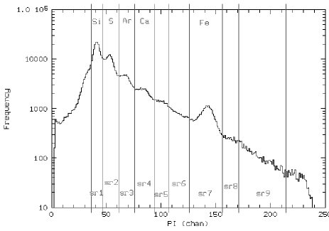
Taking into account only the well deconvolved spatial area, we have produced 9 templates (one for each spectral region) adding all images in a range and normalizing the source counts in the summed image. The deconvolved images of each PI in the same spatial area have then been compared to the relative template scaled for the source counts in that area by using the variable and assigning the statistical errors to the pixel counts:
where refers to the counts in the pixel of the deconvolved PI image, is the corresponding value in the related template, and (degrees of freedom) is the number of pixels on which is evaluated. Only pixels with more than 15 counts have been included in the computation. The variable is related to the final errors through a few simple assumptions:
-
•
the final errors are related to the statistical ones by:
where are the statistical errors and is the correction factor, always greater than 1;
-
•
the deconvolution introduces errors that at first order do not depend on the position in the image, i.e. is constant over each PI image.
Following these two assumptions, and being the expected value of the reduced equal to 1, we obtain:
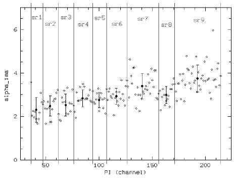
Fig. 7 plots the values found at the different PI channels. The average value of in each template region is also shown with its relative error (root-mean-square deviation).
A.2 Method II: spectra based
We implemented a second procedure following the hypothesis that in each spectrum the spread of the points respect to a model, that well describe the general behaviour, must be within the errors. We chosen to analyze only spectra having a total number of counts greater than 4104: in these spectra in fact the statistics of most of the energy channels is sufficiently high to allows us to use the test without rebinning. Actually, some of the high energy channels present very low or zero counts; however, for homogeneity and to easily automize the procedure, we did not rebin spectral channel.
We fitted the selected spectra (a total of 24) using a model that, although it does not correctly describe the emission mechanism of the source, gives a flat distribution of the residuals for all the spectra. The fitting model is composed by a power-law plus 9 lines. All parameters are left free to vary but the line widths that are kept fixed to zero. The MECS response matrix and the background spectrum are the same used for the spectral analysis described in Sect. 4. The spread of the residuals with respect to the zero level is not uniform over the whole range: high energy channels present a wider spread respect to the low energy ones.
To compute the final errors we need to set some assumptions:
-
•
the final errors are related to the statistical ones by the same formula as in Method I (Sect. A.1):
where are the statistical errors and is the correction factor;
-
•
the value of is a function of the PI channel and does not depend on the counts detected in it;
-
•
can be approximated to a step function of PI being constant within each given energy range.
Note that these assumptions are equivalent to those used in the image based method (Sect. A.1) and are based on the hypothesis that mainly depends on the statistics of the deconvolved images.
Following these assumptions we divided our spectra in 9 energy ranges coincident with the ones used in Method I (see Fig. 6). Within each of these ranges is assumed constant and related to , computed using the statistical errors, by the following formulas:
By assuming , we obtain
where is ranging within the given energy range, are the counts relative to the fitting model in the PI channel, and are the counts detected in the same channel. Note that corresponds to the value of (used in Method I) at the given PI channel, being the pixel where the spectrum has been accumulated.
We evaluated the contribution to the in the 9 defined energy bands for each selected spectrum. Following the assumption that is only function of the PI, we averaged the 24 values obtained in each of the regions assuming as error the root-mean-square deviation from the mean. Fig. 8 shows the computed together with their mean value averaged over the 24 analyzed spectra.

A.3 Correction Factor
Fig. 9 shows the comparison between the correction factors and evaluated through the two methods, image and spectra based, respectively. The values of and are always compatible within the errors. The higher discrepancy can be observed in the first () and last () point. In the interval, is higher than the corresponding ; a possible explanation is that this range contains the most statistical images and the hypothesis that the correction factor is independent from the counts in the pixel could not be sufficient: the averaged over the whole image is higher than the one relative to the most statistical pixels. In the case of the interval, is lower than the corresponding being strongly affected by the PI channels with low or zero counts (these are not included in the computation of ).
We then computed the error correction factor from the relation vs PI channel number (Fig. 7). Fitting these points with a line we get the following parameters:
The rms of the points respect to the line is 0.5.

References
- Anderson et al., (1991) Anderson M., Rudnick L., Leppik P., et al., 1991, ApJ 373, 146
- Becker et al., (1979) Becker R.H., Holt S.S., Smith B.W., et al., 1979, ApJ 234, L73
- Bleeker et al., (2000) Bleeker J.A.M., Willingale R., van der Heyden K., et al., 2000, A&A, in press (astro-ph/0010606)
- (4) Boella G., Butler R.C., Perola G.C., et al., 1997a, A&AS 122, 299
- (5) Boella G., Chiappetti L., Conti G., et al., 1997b, A&AS 122, 327
- Borkowski et al., (1996) Borkowski K., Szymkowiak A.E., Blondin J.M., Sarazin C.L., 1996, ApJ 466, 866
- Chakrabarty et al., (2000) Chakrabarty D., Pivovaroff M.J., Hernquist L.E., et al., 2000, ApJ, in press (astro-ph/0001026)
- Chiappetti et al., (1998) Chiappetti L., et al., 1998, A guided tour to the MECS and to its response matrix, http://sax.ifctr.mi.cnr.it/Sax/Mecs
- Davison et al., (1976) Davison P.J.N., Culhane J.L., Mitchell R.J., 1976, ApJ 206, L37
- Fabian et al., (1980) Fabian A.C., Willingale R., Pye J.P., et al,. 1980, Mon. Notes R. Astron. Soc. 193, 175
- Favata et al., (1997) Favata F., Vink J., Dal Fiume D., et al., 1997, A&A 324, L49
- Fensen & Gunderson, (1996) Fensen R.A. and Gunderson K.S., 1996, ApJ 470, 967 1997, A&A 324, L49
- Fujimoto et al., (1995) Fujimoto R., Tanaka Y., Inoue H., et al., 1995, PASJ 47, L31
- Hill et al., (1975) Hill R.W., Burginyon G.A., Seward F.D., 1975, ApJ 200, 158
- Holt et al., (1994) Holt S.S., Gotthelf E.V., Tsunemi H., Negoro H., 1994, PASJ 46, L151
- Hughes et al., (2000) Hughes J.P., Rakowski C.E., Burrows D.N., Slane P.O., 2000, ApJ 528, L109
- Hwang & Gotthelf, (1997) Hwang U. and Gotthelf E.V., 1997, ApJ 475, 665
- Hwang et al., (2000) Hwang U., Holt S.S., Petre R., 2000, ApJ 537, L119
- Jansen et al., (1988) Jansen F., Smith A., Bleeker J.A.M., et al., 1988, ApJ 331, 949
- Kehohane et al., (1996) Keohane J.W., Rudnick L., Anderson M., 1996, ApJ 466, 309
- Lawrence et al., (1995) Lawrence S.S., MacAlpine G.M., Uomoto A., et al., 1995, AJ 109, 2635
- Limongi et al., (2000) Limongi M., Straniero O., Chieffi A., 2000, ApJS, in press
- Lucy, (1974) Lucy L.B. 1974, AJ 79, 745
- Maccarone et al., (1998) Maccarone M.C., Grandi P., Mineo T., et al., 1998, Nucl. Ph. B (Proc. Suppl) 69/1-3, 74
- Maccarone, (1998) Maccarone M.C., 1998, Imaging of Spectral Features of Cas A. Part I: methods, procedures, early results, IFCAI Techn.Rep.2/98
- Maccarone & Mineo, (1999) Maccarone M.C. and Mineo T., 1999, Imaging of Spectral Features of Cas A. Part II: spatially resolved spectroscopy, IFCAI Techn.Rep.5/99
- McKee & Truelove, (1995) McKee C.F. and Truelove J.K., 1995, Phys. Reports 256, 157
- Markert et al., (1983) Markert T.H., Canizares C.R., Clark G.W., Winkler P.F., 1983, ApJ 268, 134
- Molendi et al., (1997) Molendi S., Chiappetti L., Cusumano G., et al,. 1997, Mem. Soc. Astron. Ital. 68, 113
- Murray et al., (1979) Murray S.S., Fabbiano G., Fabian A.C., et al., 1979, ApJ 234, L69
- Pravdo et al., (1976) Pravdo S.H., Becker R.H., Boldt E.A., et al., 1976, ApJ 206, L41
- Reed et al., (1995) Reed J.E., Hester J.J., Fabian A.C., Winkler P.F., 1995, ApJ 440, 706
- Tsunemi et al., (1986) Tsunemi H., Yamashita K., Masai K., Hayakawa S. and Koyama K., 1986, ApJ 306, 248
- Vink et al., (1996) Vink J., Kaastra J.S., Bleeker J.A.M., 1996, A&A 307, L41
- Vink et al., (1998) Vink J., Bloemen H., Kaastra J.S., Bleeker J.A.M., 1998, A&A 339, 201
- Vink et al., (1999) Vink J., Maccarone M.C., Kaastra J.S., et al., 1999, A&AS 344, 289