Status of the CANGAROO-III Project
Abstract
The CANGAROO-III project, a system of four 10 m telecopes dedicated for gamma-ray astrophysics, has started in 1999 and is expected to complete in 2004 in Woomera, South Australia. We report the construction work during the first year, which includes the completion of the first 10 m telescope built as a 7 m telescope in 1999, and the work in progess to increase the performance by constructing three more similar telescopes based on the experience gained during the construction of the first telescope.
Introduction
The CANGAROO-III is a project to study celestial gamma-rays in the 100 GeV region utilizing a stereoscopic observation of Cherenkov light flashes with an array of four 10-meter telescopes Mori99a , following the CANGAROO-I (3.8 m) Hara93 and CANGAROO-II (7 m) telescopes Tanimori99 Mori99 Kubo99 in Woomera, South Australia (E, S, 160m a.s.l.)333Visit our website for the latest information: http://icrhp9.icrr.u-tokyo.ac.jp.
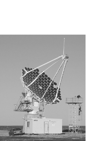
It has officially started in April 1999 and is planned as a five-year program. In February 2000 we have expanded the 7 m telescope to 10 m, which is the first telescope of the CANGAROO-III array (Fig. 1). This year we are building the second telescope in Japan which will be shipped and installed in 2001. The other two telescopes will be installed in the fourth and fifth years. Each telescope will be set on a corner of a diamond of about 100 m side in order to have a maximum number of pairs of telescopes of the same baseline length. The first stereoscopic observation will be performed in 2002 and the full four telescope will be in operation in 2004.
The First 10 m Telescope
10 m reflector
The reflector of the 7 m telescope is described elsewhere Kawachi99 : its support structure was designed to be 10 m in diameter with an 8 m focal length and the extension was simple: just adding 54 mirrors of 80 cm in diameter and increasing the counterweights. However, mounting mirrors on the reflector without dismantling the telescope was not an easy task since we had to work on a high platform. We completed this work in two weeks using a large crane.
Adjusting the mirrors to a common focus was also a challenge. A flood light placed 5 km away worked as a light source providing parallel light. Instead of covering all mirrors except the mirror being worked on which was the method used in tuning the 7 m telescope, we adjusted mirrors using a mask to select a image of each mirror 40cm before the focal plane. Then we could tune the attitude of each mirror by stepping-motor control, so that the image appeared at the expected position on the mask . The image of a star was measured with a CCD camera and its size (FWHM) is . This is a little worse than the 7 m telescope but expected because of the elongated images formed by the outer mirrors.
Camera
We have added 40 PMTs to the prime focus camera to enlarge the field of view of the camera. Now the camera has 552 PMTs of half-inch diameter and subtends about 3 degrees in octagon shape. The camera housing itself was replaced in order to reject stray light coming from outside of the reflector.
Electronics
Now the signals from PMTs are fed into analog-buffer amplifiers. One output goes to the existing front-end module (discriminator and scaler) and the other goes to newly developed VME-based ADCs (9U height, 32 ch/board, 12 bit resolution, 0.25 pC/count, 150 ns internal delay, 50 ns gate width), thus enhancing the pulse height resolution and dynamic range. The discriminated signals are sent to TDCs to measure timing and pulse width as before.
Observation
Observation resumed in March 2000 with the 10 m reflector and ADCs are working since April 2000. Target objects were selected from our list of TeV gamma-ray souces: SN1006, PSR1706-44 and RXJ1713.7-3946 in order to confirm our previous detections with the 3.8m telescope (see Ref.Mori99a for a list of observations with the 3.8m telescope). Also nearby X-ray selected BL Lacs: PKS2005-489, PKS2155-304 were observed along with multiwavelength campaigns. Data analysis is underway and will be reported soon. A preliminary comparison of data with a Monte Carlo simulation suggests the threshold energy for a proton shower is around 600 GeV.
Work in Progress for New Telescopes
Mirrors
The CFRP mirrors of 80 cm in diameter and m in curvature radius developed for the CANGAROO-II telescope are very light and durable Kawachi99 . Refining the manufacturing process of them are underway so as to produce better quality mirrors and to obtain a better yield.
Camera design
The new design of a camera will be in hexagonal shape so that the dead space between PMTs are minimal. The field-of-view will be with 427 3/4” PMTs (Hamamatsu R3478) of size larger than those of the CANGAROO-II telescope. Light guides to increase the light collection are redesigned to match the new PMT arrangement. Signals from PMTs are amplified at the camera and sent to the electronics via twisted-pair cables to minimize the weight. High voltages are supplied to PMTs individually from the ground electronics so that the gains can be tuned remotely. Now we will apply positive high voltages to PMTs to solve the discharging problem when the humidity is high in winter.
Electronics
The new electronics system will be all VME-based. The front-end circuit (under development, 16 ch/VME-9U) amplifies the signal and feeds to an ADC (the improved type of those used in the CANGAROO-II with faster conversion), discriminates it and feeds to a TDC (64 ch/VME-6U), an internal scaler and a trigger circuit. The new pattern trigger circuit using PLD devices are under development to reduce unwanted triggers caused by night sky background.
Increased data size requires faster data acquisition. Now we are testing several possibilities including VME-based Pentium CPU board running a Linux operating system, which shows faster task switching, reducing deadtime of data acquisition.
Monitor
Event data will be sampled and displayed on-line at a central control room. Scaler data which can act as a star sensor are acquired independently, reducing the load on the data-taking computers. A blue LED set at the pole of the reflector is used for field-flattening of the camera sensitivity every night. A cloud monitor which detects far infrared light Dowden97 will be used to monitor sky condition. Weather data and temperatures in electronics will be recorded as house-keeping data. These environmental monitor data are acquired through network and stored with event data. Telescope tracking will be controlled by networked computers and its accuracy will be checked with optical CCD cameras by observing stars. A light pulser source to monitor telescope performance has been developed and is being tested at the 10m telescope Patterson00 .
Summary
The CANGAROO-III will be the first array of telescopes in the southern hemisphere exploring sub-TeV region of the sky. The HESS array in Namibia, also under construction, is very welcome since the difference in time zone makes the sky coverage for transient sources wider, and should provide useful confirmation.
References
- (1) Mori, M. et al., GeV-TeV Gamma Ray Astrophysics Workshop (eds. B.L. Dingus et al.), AIP Proceedings 515, p. 485 (2000).
- (2) Hara, T. et al., Nucl. Inst. Meth., A332, 300 (1993).
- (3) Tanimori, T. et al., Proc. 26th ICRC (Salt Lake City, Utah, USA), OG.4.3.04 (1999).
- (4) Mori, M. et al., Proc. 26th ICRC (Salt Lake City, Utah, USA), OG.4.3.31 (1999).
- (5) Kubo, H. et al., GeV-TeV Gamma Ray Astrophysics Workshop (eds. B.L. Dingus et al.), AIP Proceedings 515, p. 313 (2000).
- (6) Kawachi, A. et al., GeV-TeV Gamma Ray Astrophysics Workshop (eds. B.L. Dingus et al.), AIP Proceedings 515, p. 383 (2000); Kawachi, A. et al., Proc. 26th ICRC (Salt Lake City, Utah, USA), OG.4.3.05 (1999); Kawachi, A. et al., Astroparticle Physics (in press).
- (7) Dowden, S., Patterson, J. R., Wild, N., Meas. Sci. Technol., 8, 1258 (1997).
- (8) Patterson, J. R., in these proceedings.