First images on the sky from a hyper telescope††thanks: Based on observations performed at the Observatoire de Haute Provence
Abstract
We show star images obtained with a miniature “densified pupil imaging interferometer” also called a hyper-telescope. The formation of such images violates a “golden rule of imaging interferometers” which appeared to forbid the use of interferometric arrangements differing from a Fizeau interferometer. These produce useless images when the sub-apertures spacing is much wider than their size, owing to diffraction through the sub-apertures. The hyper-telescope arrangement solves these problems opening the way towards multi-kilometer imaging arrays in space. We experimentally obtain an intensity gain of when a densified-pupil interferometer is compared to an equivalent Fizeau-type interferometer and show images of the double star Gem. The initial results presented confirm the possibility of directly obtaining high resolution and high dynamic range images in the recombined focal plane of a large interferometer if enough elements are used.
Key Words.:
Interferometers –double star images– laboratory images– pupil densification1 Introduction
The possibility of obtaining direct usable images at the combined focus of a diluted interferometric array was long overlooked. Theoretical work on densified pupil interferometry Labeyrie (1996, 1999), numerical simulations of its imaging properties Boccaletti et al. (2000) and a new algorithm for co-phasing a diluted array of several apertures Pedretti and Labeyrie (1999); Pedretti (1999) now open a new evolutionary track towards large optical arrays in space and on ground.
Fizeau optical arrays, the equivalent of a telescope carrying a multi-hole aperture mask, have imaging properties similar to telescopes. If Rayleigh’s criterion is met, there is a peaked spread function which becomes convolved with features of the observed object. Field is infinite in principle, although limited by telescope aberrations. If the holes in the mask are much smaller than their spacing however, the spread function has a vast halo of diffracted light surrounding its central interference peak. This removes most energy from the peak and creates a useless continuous level in the image. The ensuing image degradation would become disastrous in the giant systems, spreading across kilometers, considered for space interferometry with metre-sized mirrors as aperture elements
Michelson Michelson and Pease (1921), in his 20-feet beam, avoided the halo problem by densifying the exit pupil with his four-mirror periscopic arrangement, i.e, giving it a higher sub-pupil size/spacing ratio than in the entrance aperture. This caused the spread function to lose its field invariance: fringes were moving across the diffractive halo if a point source moved. The convolution thus no longer applied. Extended versions of Michelson’s beam, using many apertures instead of two, were considered since the 1970’s, but the loss of the convolution relation appeared to make them incapable of forming direct images Labeyrie (1985); Beckers (1986). The point was formalized into a “golden rule of imaging interferometry” Traub (1986).
Only much later did it appear that the rule can be evaded Labeyrie (1996), with considerable benefit in terms of future applications. It was shown that a densified pupil such as Michelson’s arrangement, but incorporating many elements, can provide direct images if the sub-pupil centres are preserved in terms of their relative locations. The image formation may then be described as a “pseudo-convolution” Labeyrie (1996), where two functions:
-
•
a field-invariant ”interference function”, which is the Fourier transform of the sub-pupil centres array,
-
•
a broad ”diffraction function” which is the Fourier transform of a single sub-pupil,
move at different speed when a point source moves away from the central axis of the instrument. The interference function moves faster than the diffraction function, the speed depending on the densification factor. If the densification factor is large then the movement of the diffraction function with respect to the interference function, becomes negligible111If the densification factor is one, the two functions move at the same speed and the pseudoconvolution becomes a normal convolution. This is the case of the Fizeau interferometer. .
The diffractive envelope can then be considered a static windowing function, limiting the angular span of the interference function. Inside the envelope, an ordinary convolution of the object with the interference function, takes place .
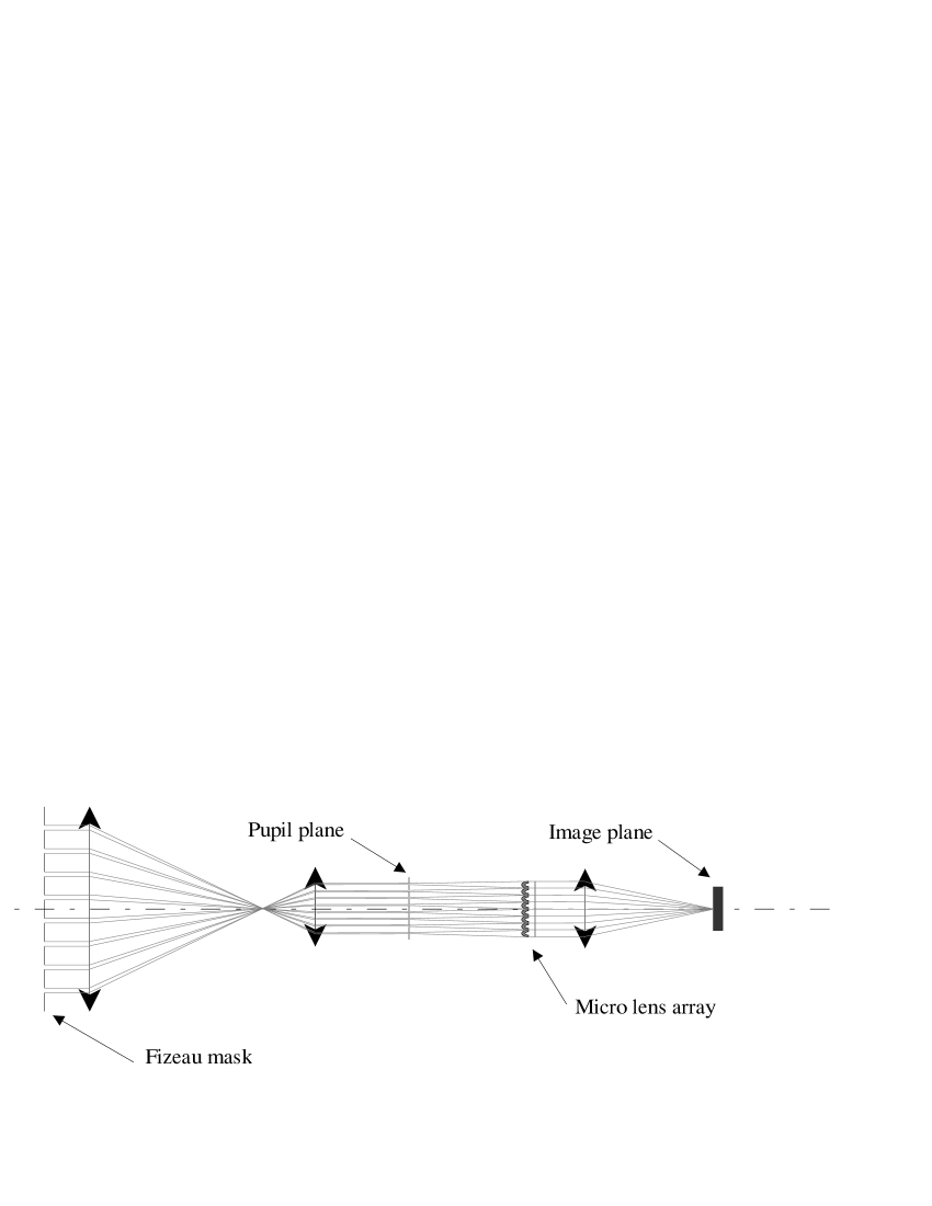
Systems other than the Michelson beam can be used to densify the exit pupil. Labeyrie proposed the system shown in Fig. 1 Labeyrie (1999) which utilises 2 micro lens arrays to re-image the exit pupils as nearly contiguous wavefront segments.
Here we show the first images obtained on the double star Gem from a miniature hyper-telescope proving that snapshot, high dynamic range images are obtainable from a Michelson type array.
2 Experimental Setup
Following the theoretical work which established the feasibility and imaging properties of hyper-telescopes, verifications were first made through computer simulations, followed by a laboratory system and a miniature hyper-telescope tested on the sky.
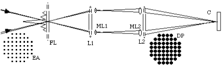
The latter instrument consists of a afocal refracting telescope the aperture of which is masked with a square array of holes of , regularly spaced by . An eyepiece produces an exit pupil image 8 times smaller thus containing sub-pupils spaced apart. The densification is achieved with an array of micro-lenses of similar pitch located downstream where the beams from each sub-pupil are spread out by diffraction in such a way that their central lobe fills the facing micro-lens in the array. These lenses having focal length provide parallel and nearly adjacent collimated beams expanded from to , achieving a densification factor of about . At the focus of a lens located immediately downstream, the central interference peak obtained is intensified with respect to the equivalent but non densified Fizeau array. This micro-lens array, obtained commercially, was modified by immersing its active face in silicon elastomer, a medium having a slightly lower refractive index than the lenses’ material, in order to lower the optical path difference (from now on OPD) caused by unequal thickness of the micro-lenses. With its aperture diameter of this miniature array has FWHM angular resolution ( in the diagonal direction) and a usable interferometric field of view of for a wavelength (the centre band for the detector used). Larger arrays would require adaptive optics unless used in speckle interferometry mode. We recorded the images in the focal plane of the interferometer array using a commercial Peltier cooled CCD, camera with pixel size.
3 Laboratory results
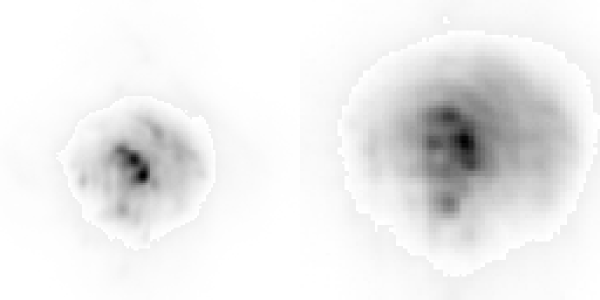
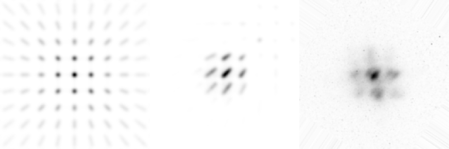
The interferometer was aligned and tested in the laboratory with an artificial star using a laser and a quartz-iodine bulb for white light. After the alignment was completed the imaging capabilities of the interferometric array were tested by replacing the pin hole placed in front of the white source with a multi-hole mask simulating a multiple star. Fig. 3 (left) shows a simulated triple system and a cluster of 6 objects (right).
Owing to the unequal thickness of micro-lenses in the array, used initially without immersion, the images obtained at this stage were not correctly phased and exhibited a speckle pattern rather than the expected interference peak. As expected, the speckle pattern was observed to become double when observing a binary artificial star, thus confirming that large hyper-telescopes will be usable for speckle interferometry when not phased adaptively.
In such large hyper-telescopes adaptive piston phasing will however be desirable, in addition to adaptive optics within the sub-apertures. We recall that speckle interferometry does not have an equally good imaging performance for complex objects.
The first micro-lens array can be removed if the sub-pupil size is small enough that diffraction suffices to fill the facing micro-lenses of the second array. This also facilitates somewhat the phasing and makes the alignment easier at the cost of an increased difficulty in controlling the size of the diffraction lobe on the micro lenses. We discuss this effect in Sect. 5
4 Sky results
The miniature hyper telescope was tested on the sky (Fig. 4).
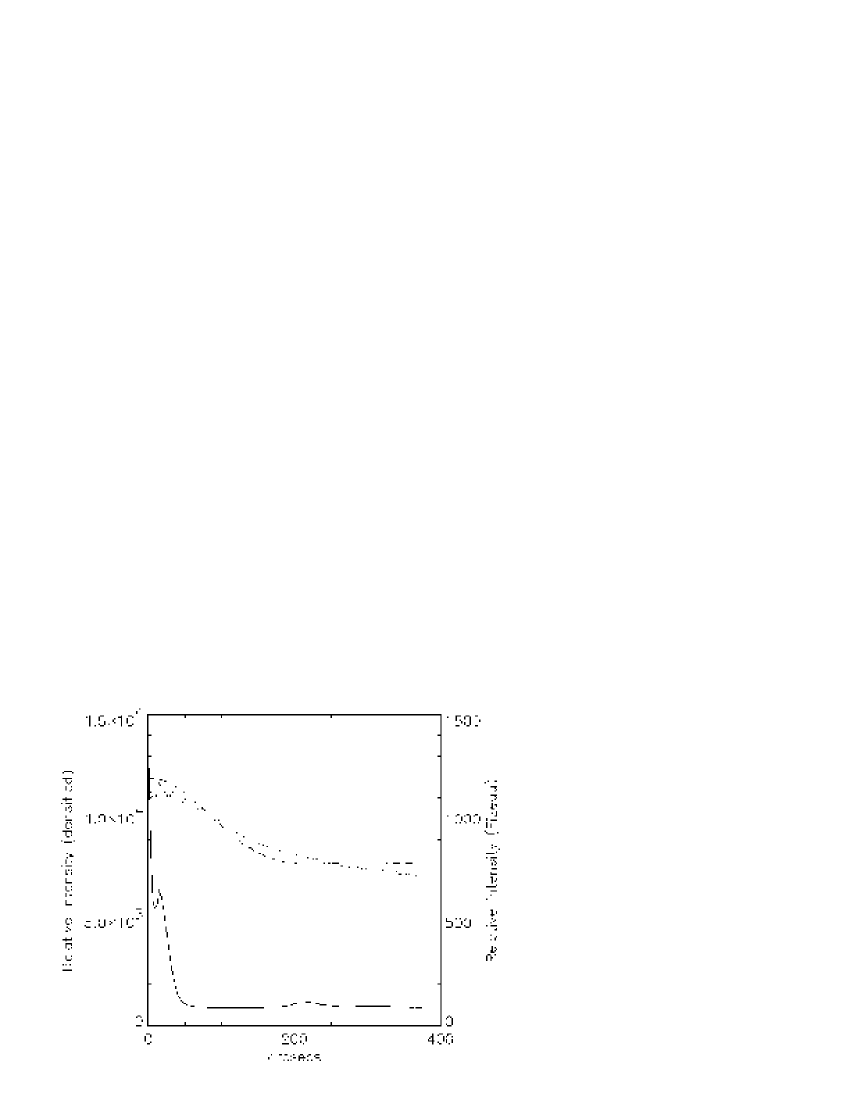
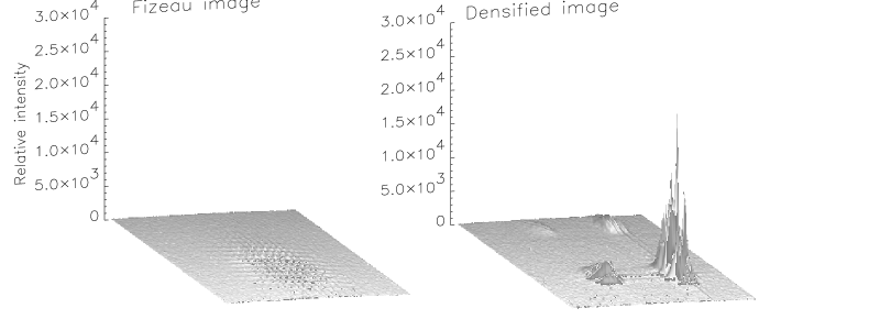
This image was obtained on the star Capella (a close binary which is completely unresolved here) by taking two separate exposures of in the Fizeau and densified-pupil mode of the hyper-telescope. It is of interest to calculate the intensification achieved in the densified-pupil case comparing the 2 images of Fig. 4. We start off calculating the theoretical intensity gain, in the central peak, for the 2 instrumental configurations. For an unresolved star the photon count in the central peak is where is the photon count from a single, unresolved star, the output sub–pupil diameter and the output pupil diameter Labeyrie (1996). In the case of our interferometer the value of is with the micro-lenses removed (Fizeau) and with the micro-lenses in place (densified pupil). Substituting these values in the previous equation and dividing the densified pupil photon count by the Fizeau photon count we find a value of for the intensification.
We then calculate the intensification factor from the images used for generating the plots of Fig. 4. For the densified pupil image and the Fizeau image, the intensity was measured by integrating the central peak. The measurements were repeated for the Fizeau and densified configuration, using several recorded images. The comparison of the obtained values showed an intensity gain of of the densified with respect to the Fizeau configuration. When we take into account the stray light introduced in the measurement, caused by the instrument not being properly baffled we obtain a value of , closer to the theoretical value. The stray light produced a constant offset in both the Fizeau and densified pupil image. The value of this offset was calculated from the Fizeau image by fitting to the measured data an Airy function corresponding to the diffraction function of the entrance apertures (Fig. 4). After the first minimum at the function is nearly constant and its corresponding value can be subtracted from the intensity calculation of the Fizeau and densified pupil images. We verified that the discrepancy between the Airy fit and the data, towards the end of the plot, was due to the detector response threshold at low light intensity levels. This effect was found in several other images. The data plot is also affected by photon and atmospheric noise. The remaining discrepancy between the theoretical and the measured intensification is probably caused by the residual optical path errors introduced by the micro-lenses unequal thickness, the atmosphere and the misalignment of the micro-lenses with respect to the Fizeau mask.
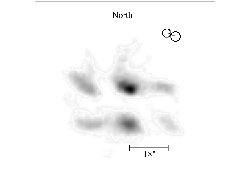
Given its miniature size, narrow field and modest collecting area (), comparable to that of a naked human eye, the hyper-telescope was tested on bright binary stars. Fig. 5 shows the image obtained on Gem the night of December the 3rd 1999 with a exposure. This image is compared to the calculated position angle and separation of the system for in Fig. 5
The orbital parameters of the star were obtained from the Washington Double Star catalog. The angular separation and the position angle were calculated using the peak pattern produced by the array. The period of the peaks is in fact equal to ; we found a value for the angular separation. The position angle measured on the photo centres of the double star image produced a value of . This values agree with the calculated separation and position angle
5 Discussion
The use of a square grid aperture was dictated by the geometry of the micro lenses used, which permitted to easily achieve pupil densification. Periodic arrays, with either square or hexagonal pitch, have interference functions similarly having a periodic array of peaks of uniform height. Non-periodic arrays, composed, for example, of concentric rings of apertures providing little or no redundancy have a speckled halo of side-lobes in their interference function. The average level of this halo is N times fainter than the interference peak, assumed perfectly phased.
We found that acquiring the image requires a pointing accuracy better than , corresponding to the distance of the first dispersed side lobes. The wavefront propagating from the star must be parallel to the main axis because an angle of the wavefront with the axis produces an increase of the OPD among the different apertures. As a result the white light central peak is shifted outside the magnified diffraction function. Since the array behaves as a bi-dimensional grating one of the dispersed peak may be found in the centre of the diffraction function. This will still form an image but dispersed and so elongated in one direction (Fig. 6).
A disadvantage of Michelson with respect to Fizeau arrays is the limited field of view. This is noticeable for an object moving off axis on the sky: the diffraction envelope from the sub–pupils moves with a lower speed than the interference peak forming the image, the speed proportional to the densification factor Labeyrie (1996). From this observation, we define the field of view for a densified pupil interferometer as the angular extent on the sky over which the white image of stars remains inside the diffraction envelope of the sub–pupils. Owing to the pupil densification, the field thus defined is typically much narrower than the Airy radius of the sub-apertures on the sky. Following this definition, the field of view for a densified pupil interferometer depends on the amount of densification achieved. Maximum densification is achieved when the sub–pupils become adjacent. When this occurs the first dispersed side lobes coincide with the first zero of the diffraction function. In the practical case of our array we did not reach the maximum pupil densification since the first side lobes are still visible. The distance between 2 apertures is ; in the image plane the angular distance between the central white light peak and the first dispersed peak is then giving slightly larger than ( and as previously defined).
The basic gain of densified-pupil imaging , with respect to Fizeau, is that the concentration of energy from a halo of many dispersed peaks into a single white central peak intensifies the main image, thus increasing its ratio to photon-noise. A more accurate device would contain 2 micro lens arrays working in an afocal configuration to meet the requirements of geometrical optics as sketched in Fig. 1. In the current device, shown in Fig. 2, the diffracted Airy patterns from the sub-apertures have their feet which fall upon neighbouring micro-lenses and this produces “ghost images” in the focal plane shown in Fig. 4. The shape of the high resolution peak is not affected but its intensity is thus slightly reduced. Other losses in the system are caused by the imperfect alignment of the diffracted sub-pupils with the micro-lenses. This effect is seen as an asymmetric intensification of the side dispersed peaks with respect to the central white light peak. Most important perhaps, the phasing of the micro-lenses is less than perfect. This affects the intensity of the interference peak and creates a speckled halo around it.
6 Conclusions
The rather modest scale of the miniature hyper-telescope sufficed to verify the theory of its operation and to confirm the imaging performances to be expected with future interferometers at the kilometres scale. We have verified that arrays in which the entrance and exit pupil are non homothetic can form direct images, contrary to what was commonly believed. We have also measured an intensity gain of with respect to an equivalent Fizeau array and this is considered as supporting the value obtainable in principle with perfectly phased components.
Hyper-telescope architectures are candidates for the next generation of extremely large ground-based telescopes. Aperture sizes even larger than the 30 to 100 metres, currently considered for large steerable mosaic mirrors Gilmozzi et al. (1998), can be implemented in the form of sparse mosaics. Rather than large pointing mounts, these can extend the principle of the Arecibo radio-telescope , with a fixed diluted primary mirror and moving focal optics, possibly carried by stationary balloons. This configuration appears of interest even to achieve kilometre size apertures .
In space, the situation seems more favourable and many sub-apertures can be combined in formation flight to achieve kilometre size apertures Boccaletti et al. (2000) for detecting Earth-like exo-planets Labeyrie (1999).
Acknowledgements.
This work is based on observations with the equatorial table at the Observatoire de Haute Provence and used hardware and software of the Observatoire de la Côte d’ Azur for data reduction. We thank the referee, Jacques Beckers, for his useful criticism. One of us (Ettore Pedretti) would like to thank Farrokh Vakili for his encouragement and many useful discussions.References
- Beckers (1986) Beckers, J. M., 1986, Proceedings of SPIE 628, 255
- Boccaletti et al. (2000) Boccaletti, A., Riaud, P., Moutou, C., and Labeyrie, A., 2000, Icarus 146
- Gilmozzi et al. (1998) Gilmozzi, R., Delabre, B., Dierickx, P., Hubin, N., Koch, F., Monnet, G., Quattri, M., Rigaut, F., and Wilson, R., 1998, in L. M. S. E. (ed.), Advanced Technology Optical/IR Telescopes VI, Vol. SPIE 3352, pp 778–791
- Labeyrie (1985) Labeyrie, A., 1985, in Kilometric Optical Arrays in Space, pp 117–119
- Labeyrie (1996) Labeyrie, A., 1996, A&AS 118, 517
- Labeyrie (1999) Labeyrie, A., 1999, in Working on the Fringe: An International Conference on Optical and IR Interferometry from Ground and Space, Dana Point, CA, May 24-27, 1999. Proceedings to be published in ASP Conference Series (S. Unwin and R. Stachnik, editors), p. 7., pp E7–+
- Michelson and Pease (1921) Michelson, A. A. and Pease, F. G., 1921, ”Measurement of the diameter of a Orionis with interferometer”, [Chicago, 1921]
- Pedretti (1999) Pedretti, E., 1999, in Working on the Fringe: An International Conference on Optical and IR Interferometry from Ground and Space, Dana Point, CA, May 24-27, 1999. Proceedings published in ASP Conference Series (S. Unwin and R. Stachnik, editors), p. 26., pp E26–+
- Pedretti and Labeyrie (1999) Pedretti, E. and Labeyrie, A., 1999, A&AS 137, 543
- Traub (1986) Traub, W. A., 1986, Appl. Opt. 25, 528