Irradiated Herbig-Haro Jets
in the Orion Nebula and Near NGC 1333
Abstract
We report the discovery of a dozen Herbig-Haro jets illuminated by the Lyman continuum ( 912Å) and/or softer far-ultraviolet (912Å 2000Å) radiation fields of nearby high mass stars. Five irradiated outflows lie in the outer parts of the Orion Nebula (HH 502 through HH 506) and seven lie near the reflection nebula NGC 1333 in the Perseus molecular cloud (HH 333 through HH 336, and HH 497 through HH 499). These stellar outflows are powered by optically visible low mass young stars which suffer relatively low extinction and seem not to be embedded within opaque cloud cores. We propose that the UV radiation field has eroded residual material left over from their formation on a time-scale short compared to the ages of these star forming regions. Many of the irradiated jets exhibit unusual C-shaped symmetry. In the outskirts of the Orion Nebula, most irradiated jets appear to bend away from the core of the nebula. On the other hand, in NGC 1333, the C-shaped jets tend to bend back towards the cluster center. Jet bending in the Orion Nebula may be dominated by either the outflow of material from the nebular core or by the rocket effect pushing on the irradiated portion of a mostly neutral jet beam. But in NGC 1333, jet bending may indicate that the source stars have been ejected from the cluster core. Many irradiated jets are asymmetric with one beam much brighter than the other. When fully photo-ionized, irradiated jets may provide unique insights into the physical conditions within outflows powered by young stars, permitting the determination of the density and location of stellar ejecta even in the absence of shocks. We present a model for the photo-ionization of these outflows by external radiation fields and discuss possible mechanisms for producing the observed asymmetries. In particular, we demonstrate that the UV radiation field may alter the amount of cloud material entrained by the jet. Radiation induced variations in mass loading and beam heating can produce differences in the beam velocities and spreading rates, which in turn determine the surface brightness of the radiating plasma. In a bipolar irradiated jet in which both beams have the same mass loss rate and opening angle, the slower beam will appear brighter at a given distance from the source. On the other hand, if both beams spread orthogonal to the jet propagation direction with the same speed (e.g. both beams have the same internal sound speed or shocks with similar physical conditions), the faster beam will appear brighter at the same distance from the source. Thus, depending on the parameters, either the faster or slower beam of a jet can be brighter. Finally, we report the discovery of some large scale bow shocks which face the core of the Orion Nebula and which surround visible young stars. These wind-wind collision fronts provide further evidence for a large scale mass flow originating near the nebular core.
1 Introduction
Young stars, born from dense molecular cloud cores, frequently drive highly supersonic jets and winds which are traced by Herbig-Haro (HH) objects at visual wavelengths, near infrared emission line regions bright in molecular hydrogen and [Feii], and the ubiquitous bipolar molecular outflows observable at millimeter wavelengths. HH objects are collisionally excited nebulae produced by outflows ejected by young stellar objects (YSOs) and they either trace shocks where outflows ram the ambient cloud (terminal working surfaces) or shocks produced by colliding fluid elements ejected from the source at different velocities and times (internal working surfaces). Usually, they can be identified by their forbidden [Sii] emission and large [Sii]/H line ratio. Since Herbig-Haro objects are thought to be produced mainly during the first few hundred thousand years of the life of a YSO, most HH sources are highly obscured by the cloud cores and circumstellar environments from which they formed.
The optical emission lines which trace normal HH objects are excited by non-equilibrium processes in and behind shock waves. Therefore, the intensities of the emitted lines depend on the complex details of the flow such as the shock geometry, the structure and strength of magnetic fields, the ionization fraction, and the effects of the radiation generated by the shocks themselves on the upstream and downstream material. Therefore, it is very difficult to reliably estimate the basic physical parameters such as density, temperature, and ionization fraction and how these parameters vary across the emission region. Furthermore, it is even harder to infer the overall parameters that characterize an outflow such as the stellar mass loss rate, outflow momentum, and flow kinetic energy flux, since moving material which remains quiescent (unshocked) is not traced by these emission lines at all. Therefore, most of the mass (and therefore the momentum and kinetic energy) of an outflow may remain invisible.
Reipurth et al. (1998) recently identified four Herbig-Haro jets located near the luminous high mass multiple star system Orionis, all four of which originate from visible T-Tauri stars not embedded in opaque molecular cloud cores. The intense ultraviolet radiation field of the massive stars has ionized and removed the bulk of the interstellar matter from the YSO environment. Interestingly, all of these jets are asymmetric, with the beam facing away from Orionis being much brighter than the counter beam.
The discovery of externally irradiated HH objects such as those found by Reipurth et al. (1998) and Cernicharo et al. (1998) creates new opportunities for diagnosing outflows. In externally irradiated outflow systems, the intensity of the emission produced by a variety of spectral lines may be primarily determined by the external illumination rather than the complex physics of shocks. For example, if the external radiation field ionizes either the surface or the entire body of a jet or wind, the observed intensity of the H line can be directly related to the emission measure, and the red [Sii] lines can be used to measure the electron density. Measurements of the radial velocity field and flow morphology can be combined with these parameters to infer many flow properties such as the mass loss rate, momentum carried in each beam, and the energy injected into the cloud by the flow. Instead of relying on highly uncertain shock models, we can apply the well understood theory of photoionized nebulae to estimate outflow parameters. Furthermore, external radiation fields are likely to illuminate all unshadowed outflow components equally so that the flow structure can be determined reliably.
In this paper we report the discovery of new irradiated jets in two star forming regions; the Orion Nebula (M42, NGC 1976; d = 470 pc) and the NGC 1333 region in the Perseus molecular cloud (d = 220 pc). We first discuss the observations and present a description of each new flow. Then we present a simple photo-ionization model for irradiated jets, discuss a possible mechanism for the production of jet asymmetries, and finally explore the implications of C-shaped symmetry observed in jets contained both within the Orion Nebula and near the core of NGC 1333.
2 Observations
We obtained narrow band images of the Orion Nebula and NGC 1333 on the nights of 2830 October 1997 at the prime focus of the Mayall 4 meter telescope using the MOSAIC 8192 8192 pixel CCD camera equipped with the engineering grade CCD detectors. The field of view of this setup is approximately 36′ 36′ with a scale of 0.26″ per pixel (for details, see the MOSAIC homepage at http://www.noao.edu/kpno/mosaic/mosaic.html). To minimize the effects of bad columns and pixels, and the 40 pixel-wide gaps between the individual CCD detectors, we obtained for each field a set of five 600s exposures using a dither pattern with a spacing of 100 pixels. Images were obtained through an H narrow band filter centered on 6563 Å with a band pass of 75 Å, and through a [Sii] filter centered on 6730 Å with a band pass of 81 Å. The data were overscanned, trimmed, dark subtracted, and flat fielded using the IRAF package MSCRED. This package compensates for the geometrical distortions introduced by the 4 meter optics, including the effects of the field flattener. Dark subtraction was based on a median-combined set of eleven 600s dark exposures taken at various times throughout the observing run. A comparison of darks taken at different times during the run did not show any significant variations. Flat fielding was based on sky flats. The H flat was formed by median combining nine twilight sky flats, while the [Sii] flat was formed by median combining thirteen sky flats. After reduction, individual images were combined into a single FITS image in each filter with IRAF. An internal reflection resulting from a defective anti-reflection coating on the prime-focus field flattener/corrector produced a large doughnut shaped artifact in the images that persists at the few percent level after flat fielding and median combining. Since the amount of reflection depends critically on the location of bright objects in the imaged field, its intensity varies from image to image. This artifact is less noticeable in regions with strong emission.
Visual wavelength spectra were obtained with the RC spectrograph at 30 km s-1 resolution at the Mayall 4 m reflector at Kitt Peak, on the nights of December 26 through 30, 1998. Spectra covering the wavelength range from [Oi] 6300 to [Sii] 6731 were obtained with a 2″ wide and 5′ long slit which was oriented in each flow at the position angle listed in Table 1 using grating KPC 24 in second order and a long-pass glass order sorting filter (OG 570). The image scale of this setup was 0.69″ per pixel along the slit and 0.54Å per pixel (24 km s-1) along the dispersion direction. The 2″ slit provides a spectral resolution of about 0.7Å or 32 km s-1. For further details on the instrument and data reduction, see Devine et al. (1997). All radial velocities quoted in this paper are with respect to the velocities of the diffuse nebular lines produced by M42 and NGC 1333 which are assumed to trace the stationary ambient medium.
3 Results
3.1 Irradiated Jets in the Outskirts of the Orion Nebula
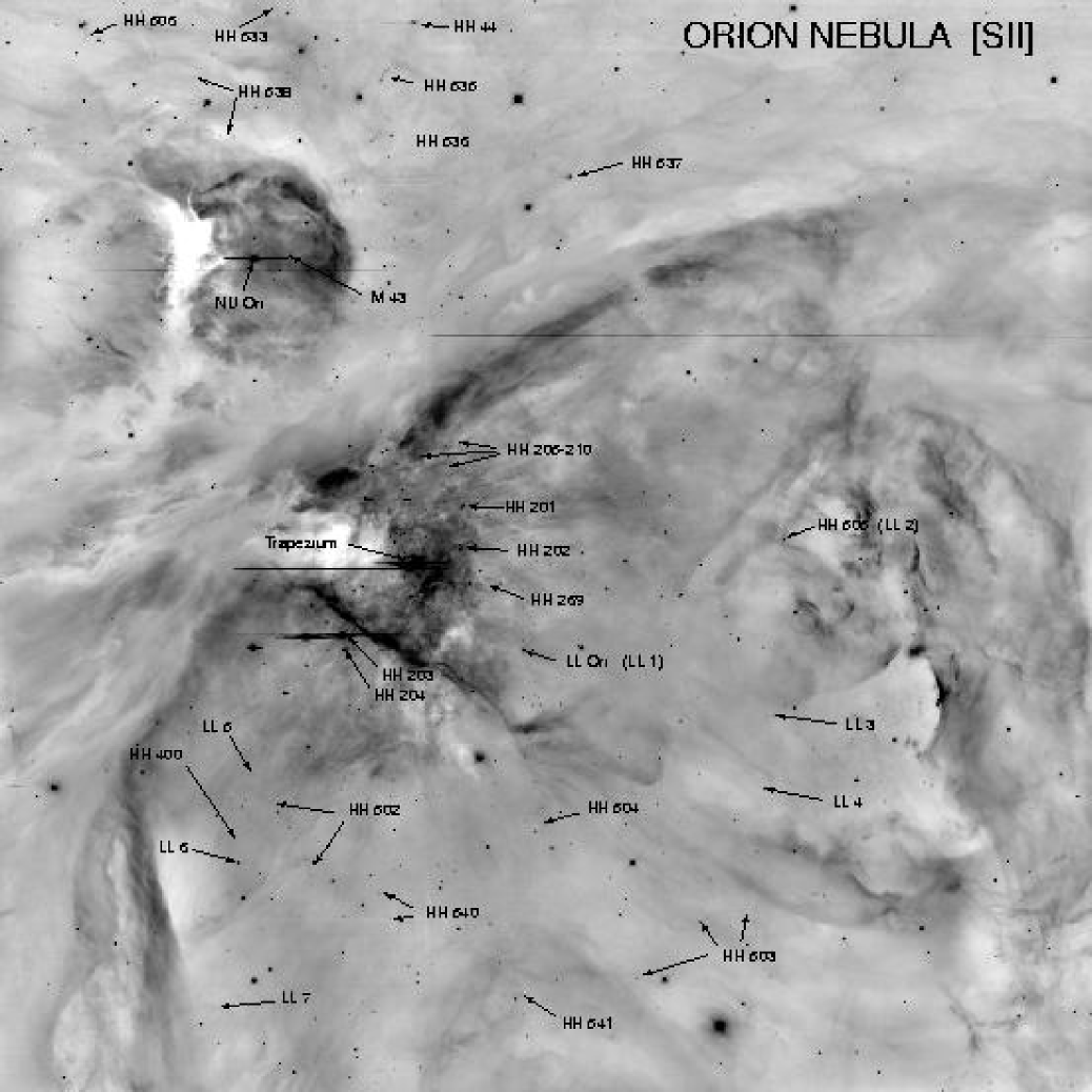
The Orion Nebula (Figure 1) is the nearest region of active high mass star formation. Located at a distance of about 470 pc, the nebula contains the Trapezium Cluster of O and early B stars and over 700 low mass stars within a region less than a few parsecs in diameter (e.g. McCaughrean & Stauffer 1994). The most luminous member, Orionis C (O6pe) is responsible for ionizing the Hii region. The ten parsec long dense filament of molecular gas at the northern end of the Orion A cloud which spawned the Orion Nebula is associated with at least 2,000 YSOs, the majority of which are less than 1 million years old (Hillenbrand 1997; Hillenbrand & Hartmann 1998). Bally, O’Dell, & McCaughrean (2000a) report the discovery of 24 compact irradiated microjets emerging from the ‘proplyds’ (an acronym for PROto PLanetarY Disk) in the nebular core.
Figures 2–6 show [Sii] and H images of the irradiated jets embedded in the outskirts of the Orion Nebula. Four irradiated jets lie in the southern and western parts of the Nebula. The appearance of these jets is likely to be dominated by the Lyman continuum (LyC or EUV) radiation field of the Trapezium stars. One jet lies towards the northeast well beyond the projected boundary of the nebula where it is likely to be only exposed to softer far ultraviolet (FUV) radiation.
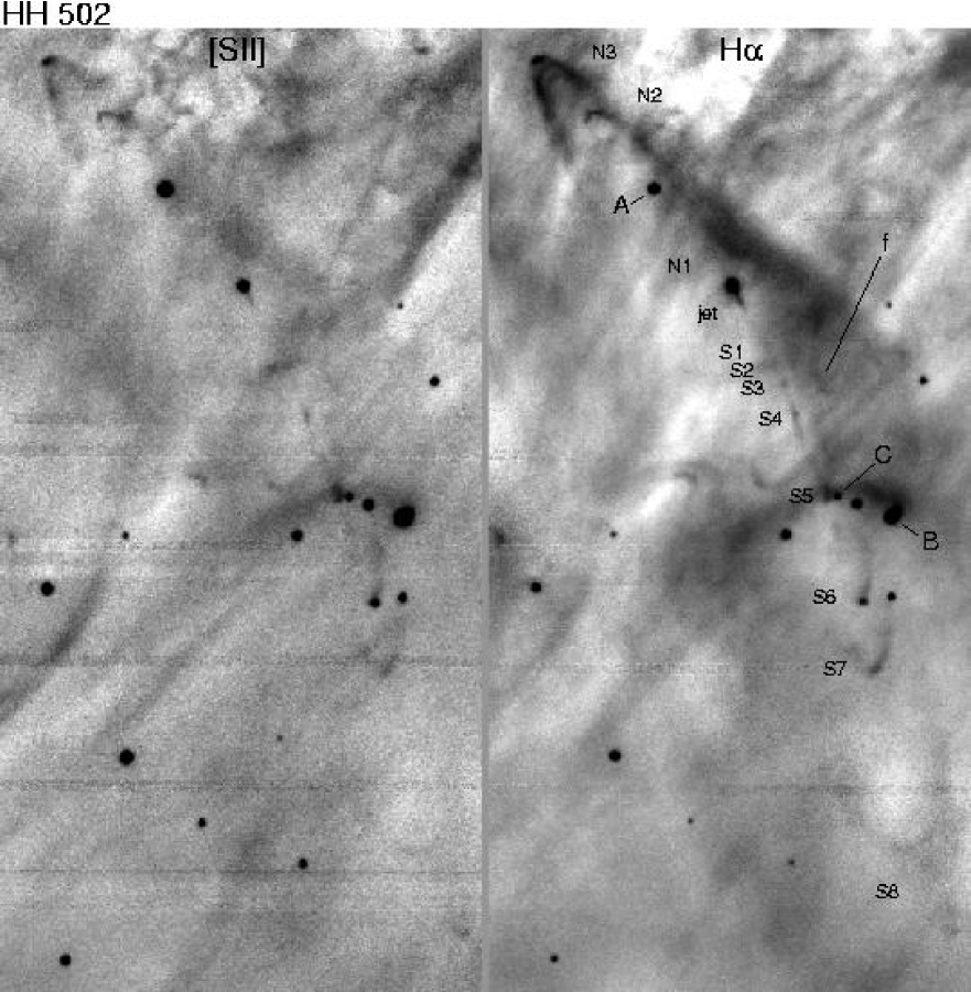
HH 502: This outflow (Figure 2) consists of a knotty 60″ long jet, extending south towards at least three bow shocks of progressively larger size and lower surface brightness that lie up to 150″ from the source. Although the counterjet is more than three times fainter, there are two relatively high surface brightness bow shocks on the north side of this outflow. Overall, the jet and the chain of bow shocks bend away from the Orion Nebula core.
The outflow originates from a 17-th magnitude H emission line star located 2.8′ east and 6.2′ south of the Trapezium ( Orionis C). The stellar H emission has an equivalent width (EW) of about 60Å and can be traced to about 700 km s-1 on either side of the nebular H emission, indicating that the source of the HH 502 jet is a classical T Tauri star. Strong forbidden [Oi] emission in the 6300 and 6363Å lines is seen from the star with EW([Oi]) 10Å in each line. This emission is predominantly redshifted by about 30 km s-1 from the nebular [Oi] emission. However, faint [Oi] line wings can be traced up to 75 km s-1 from the nebular line on top of the stellar continuum. In addition to this spatially unresolved component, the [Oi] emission also exhibits a spatially extended redshifted ( 50 km s-1) feature which in the spectra can be faintly traced for about 20″ south of the source along the direction of the jet visible in the H image (Figure 1).
The main jet from this star extends to the south at PA = 208o and is much brighter in H than in [Sii] (Table 2A, 3). Although the jet fades considerably about 5″ south of the source, it can be traced for nearly an arc minute to the south as a series of about seven knots and faint interconnecting emission. Remarkably, the jet remains unresolved in the transverse direction (width 1″) for up to 40″ from the source! The jet bends to the south by about 5° roughly 25″ south of the source. The position angles of various features in the HH 502 outflow with respect to the central star, and the deflection from the nominal launch direction of the jet are listed in Table 2A.
At least three H bow shocks are seen at intervals of about 45″ along the jet axis south of the source. Knots of [Sii] emission are found at the tips of the bows. Two H dominated bows are seen towards the opposite side of the source in the counterflow direction at PA = 40o. The three bow shocks south of the source and the two lying north of the source do not lie in a straight line, but on a curve that indicates C-shaped symmetry about the source.
Three RC Spectrograph long-slit orientations and placements were used to observe HH 502. The first slit (PA = 22° or 202°) is centered on the source star and passes near the core of the first compact bow shock (S6, located 50″ from the source) and the wings of the next bow shock (S7, located about 10″ downstream). Except within 5″ of the source, this slit orientation misses most of the curved jet which emerges towards the southwest. The second slit, (PA = 40o) is also centered on the source star and was chosen to pass through the apices of the two bow shocks lying to the northeast of the source (N2 and N3). This slit included the light of the star superimposed on the northern lobe of HH 502 (star A) and star B in Figure 1. Finally, the third slit (PA = 7o) is centered on a faint star (star C) in the southwest lobe of the HH 502 flow and passes through the brightest knots at the apices of the bow shocks S6 and S7 as well as the eastern side of S8 located 30″ downstream from S7.
The results of the spectroscopic observations of HH 502 show that: (1) The brighter southern jet is redshifted by +50 km s-1 with respect to the Orion Nebula with wings extending to about +70 km s-1. The jet kinematics is most apparent in the [Nii] lines since the H line is overwhelmed by the strong background produced by the Orion Nebula. However, unlike the H emission, the [Nii] emission is brighter towards the northern counter jet than towards the main jet that extends south of the source. Faint [Sii] emission is also visible within several arc seconds of the source on both sides. (2) The flow from the young star exhibits kinematic asymmetry with the fainter northern lobe being blueshifted by about 100 km s-1 with wings extending to about 130 km s-1. The jet and counter jet are more easily seen in [Nii] than in H due to the better contrast against the nebular background. As the [Nii] lines, the [Sii] emission also shows this kinematic asymmetry. (3) The blueshifted northern bow shocks N2 and N3 have Doppler shifts of 130 km s-1 and 70 km s-1 respectively. (4) Doppler shifts of only two of the southern bow shocks were measured. Both S6 and S7 have radial velocities of about +25 km s-1 with respect to the Orion Nebula lines. (5) All four stars which fell on the various slit orientations show evidence of youth. Star A has strong H emission and lithium 6707 in absorption. Star B, though lacking stellar H emission, exhibits a very deep lithium absorption line, and star C exhibits very strong H emission and weak lithium absorption. The source of HH 502 does not exhibit a measurable lithium absorption feature. Thus, all of these stars are likely members of the extended Trapezium cluster. (6) Finally, slit 2 reveals a 75 km s-1 feature, f, visible in H and [Nii] about 30″ southwest of the driving source of HH 502 which is not associated with the HH 502 outflow system. The H image shows a faint bow shaped emission region here.
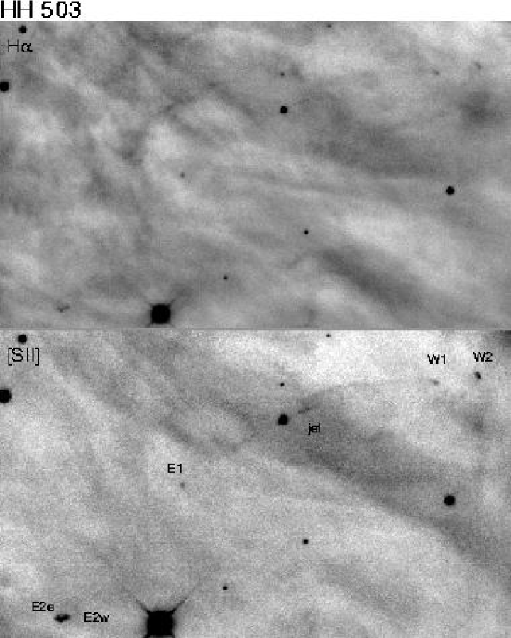
HH 503: The second most prominent irradiated jet in the outskirts of the Orion Nebula is HH 503 (Figure 3), located 9.8′ west and 2.2′ south of HH 502 (6.9′ W, 8.4′ S of Orionis C). Unlike most other irradiated jets in Hii regions, this flow has a relatively large [Sii] to H brightness ratio and is therefore seen with greater contrast against the background in the [Sii] image.
The optical bipolar outflow emerges from an H emission line star with strong lithium absorption. This star also exhibits forbidden [Oi] emission. Although a bipolar jet is visible on both sides of the star in both H and [Sii], it is highly asymmetric in brightness, with the portion of the jet extending to northwest (PA = 285°) from the star being at least four times brighter than the counterjet. The jet can be traced to a compact [Sii] dominated bow shock, HH 503 W1, about 65″ from the source star. The wings of this bow shock are highly asymmetric, with the northern side that faces the core of the Orion Nebula being much brighter and larger than the other side. The north rim of this bow can be traced for 50″ back nearly to the source star. The southern rim of this shock disappears within a few arc seconds of the tip of the bow. The extended north wing lies about 5″ north and its curvature closely follows the bent body of the jet. A second and brighter bow shock (HH 503 W2) lies about 18″ farther west. Unlike HH 503 W1, this object does not exhibit extended wings and is only about 4″ in size. The counter jet can be faintly traced towards the southeast where it terminates in a compact bow shock (HH 503 E1) about 45″ from the source. Knot E1 is the only component in this flow which has a large H to [Sii] brightness ratio (13.0) that is consistent with full photo-ionization. All of the other features in this flow have ratios ranging from 2 to 4 (Table 3). About 70″ further along the curving outflow axis lies the brightest HH objects in this flow, the double knot HH 503 E2. This structure looks like a fragmenting bow shock that is bright in both [Sii] and H. Overall, HH 503 is a highly collimated jet system with multiple bow shocks whose outflow axis appears to be bent by about 40o. Thus, the jet and the associated chain of bow shocks exhibit bending away from the core of the Orion Nebula (C-shaped symmetry).
Spectra were obtained with three different RC Spectrograph long slit positions and orientations. The slit was oriented at PA = 113o for the first two spectra. The first spectrum was centered on the driving source and the slit includes some of the brightest portions of the jet extending to the west. The second spectrum was obtained with the same slit orientation but displaced 9.8″ south so that HH 503 W1 and E1 both fell on the slit. The third spectrum, obtained at PA = 120°, includes the brighter bow shocks HH 503 W2 and E2.
This bent outflow appears to be redshifted towards the northwest and blueshifted towards the southeast based on the kinematics of knots W2 and E1. However, neither the jet nor knot W1 were detected in the spectra, presumably because of the faintness of these features. Knot W2 has a redshifted velocity of about +25 km s-1 while knot E1 is blueshifted at 25 km s-1 with faint H line wings extending to about 100 km s-1 with respect to the Orion Nebula. This wing emission suggests that the shocks in E1 have speeds of at least 50 km s-1 (Hartigan et al. 1994). Although it lies on the nominally blueshifted side of the HH 503 flow, the large and bright double bow shock E2 is redshifted, with a mean Doppler shift of about +25 km s-1 with faint emission extending up to +75 km s-1. Therefore, it is possible that E2 is not part of the HH 503 system. However, if it is, then the flow must be bent not only in the plane of the sky, but also along the line of sight. Furthermore, the four bright compact bow shocks that delineate the bent body of this bipolar flow cannot be moving ballistically from the source. Instead, the emitting material must itself have undergone a large deflection from the initial outflow launch direction both in the plane of the sky and along the line of sight. The spectra also demonstrate that the three HH objects in this flow (HH 503 E2, W1, and W2) are most prominent in the 6300Å [Oi] and in the [Sii] lines, and barely detected in H, indicating that these HH objects have large neutral components.
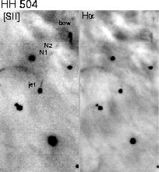
HH 504: This object (Figure 4), located 3.2′ W and 6′ S of Orionis C, consists of a 10″ long [Sii] filament extending from near a bright star towards position angle = 345o. A chain of compact [Sii] dominated knots and a compact partial bow shock lie about 30″ to the north. A peculiar feature of this jet is that the jet axis seems to miss the bright star by about 0.5″, perhaps because it originates from a fainter companion. The brightest [Sii] emission is displaced from the star towards the core of the Orion Nebula by about 1″. This jet appears to be unipolar. Several faint filaments of [Sii] emission lie about 30″ northeast of the source. Is is not clear if these features are associated with the outflow system or are unrelated objects.
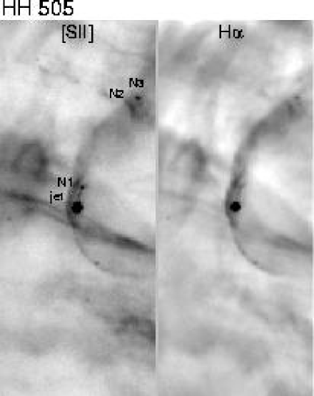
HH 505: Located 8.9′ west and 0.7′ north of Orionis C, this one-sided jet (Figure 5), most visible in the [Sii] image extends from a star at PA = 345° and terminates in a bright knot of [Sii] emission about 15″ away. A crescent shaped H bright rim wraps around the star and its unipolar jet on the side of the system facing the Orion Nebula core. The intensity distribution indicates that this feature may trace the limb brightened skin of a bubble that wraps around the star. The curvature of this arc of H emission is most pronounced near the star, which is also where the arc reaches its peak surface brightness. The H arc is similar to other predominantly H bright crescents which appear to wrap around dozens of young stars in the outskirts of the Orion Nebula (the LL Ori objects; see below).
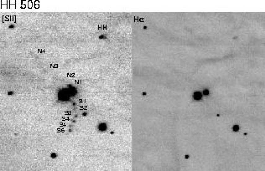
HH 506: A 4″ long jet, located 7.7′ east and 13.0′ north of Orionis C (Figure 6), emerges from a bright star at PA = 30o towards the north. The star is centered on a clumpy 60″ long curved filament of [Sii] emission that bends towards the east on both sides of the star. The southern portion of this chain contains 8 distinct compact ( 1″ diameter) knots of [Sii] emission. The northern part consists of a faint filament of emission. HH 506 is located northeast of the Orion Nebula about 10′ east of the OMC2/3 molecular ridge and is therefore outside the projected edge of the photo-ionized portion of the Orion Nebula.
This portion of the Orion region contains many extended filaments of [Sii] and H emission, and numerous HH objects. For example, a bright 10″ diameter HH complex lies about 50″ to the northwest of the HH 506 source. A fainter HH object lies 70″ away along the same direction. These objects do not appear to be connected to the HH 506 jet.
3.2 Wind-Wind Collision Fronts
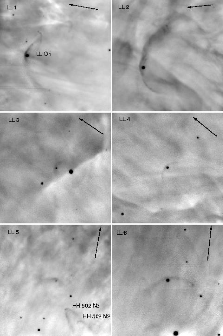
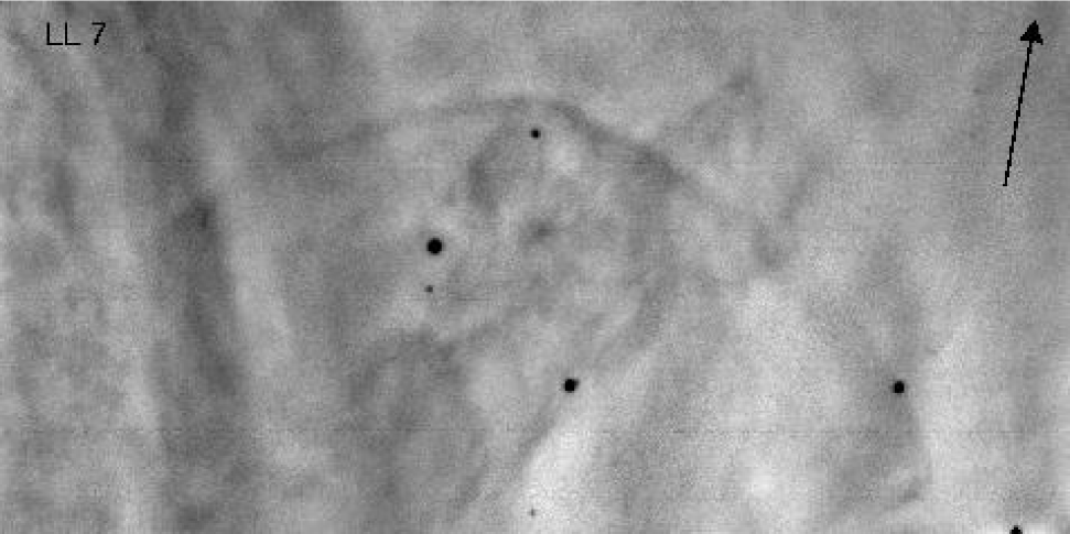
All jets in the outer portions of the Orion nebula which exhibit C-shaped symmetry bend away from the nebular core, indicating the presence of a wind or a force which can bend the jets and their cocoons. Evidence for a pervasive outflow of material from the inner nebula is provided by stars that are surrounded by bow shaped emission line features pointing towards the Trapezium cluster. The bows are symmetric about a line connecting the associated star to the Trapezium stars and range in size from about 20″ to several arc minutes. The prototype feature is associated with the star LL Ori located 1.9′ west and 2.7′ south of Orionis C (Gull & Sofia 1979; Bally et al. 2000a). The minimum projected separation between the associated star and the closest point to the arc (usually on a line connecting the star to the Trapezium) ranges from about 3″ to about 20″. These [Sii] and H bows appear to trace shock fronts at the interface between a wide angle wind emerging from the associated young star and a large scale outflow from the core of the Orion Nebula. Bally et al. (2000a) present Hubble Space Telescope observations of ten wind-wind collision fronts within the inner 4′ core region of the Orion Nebula. Bally et al. provide a detailed discussion of the mechanisms responsible for these features. The wide-field MOSAIC images reveal additional similar objects in the outer portions of the nebula. The LL Ori type wind-wind collision fronts found on these images are listed in Table 5 and shown in Figures 14 and 15.
3.3 Irradiated Jets in NGC 1333
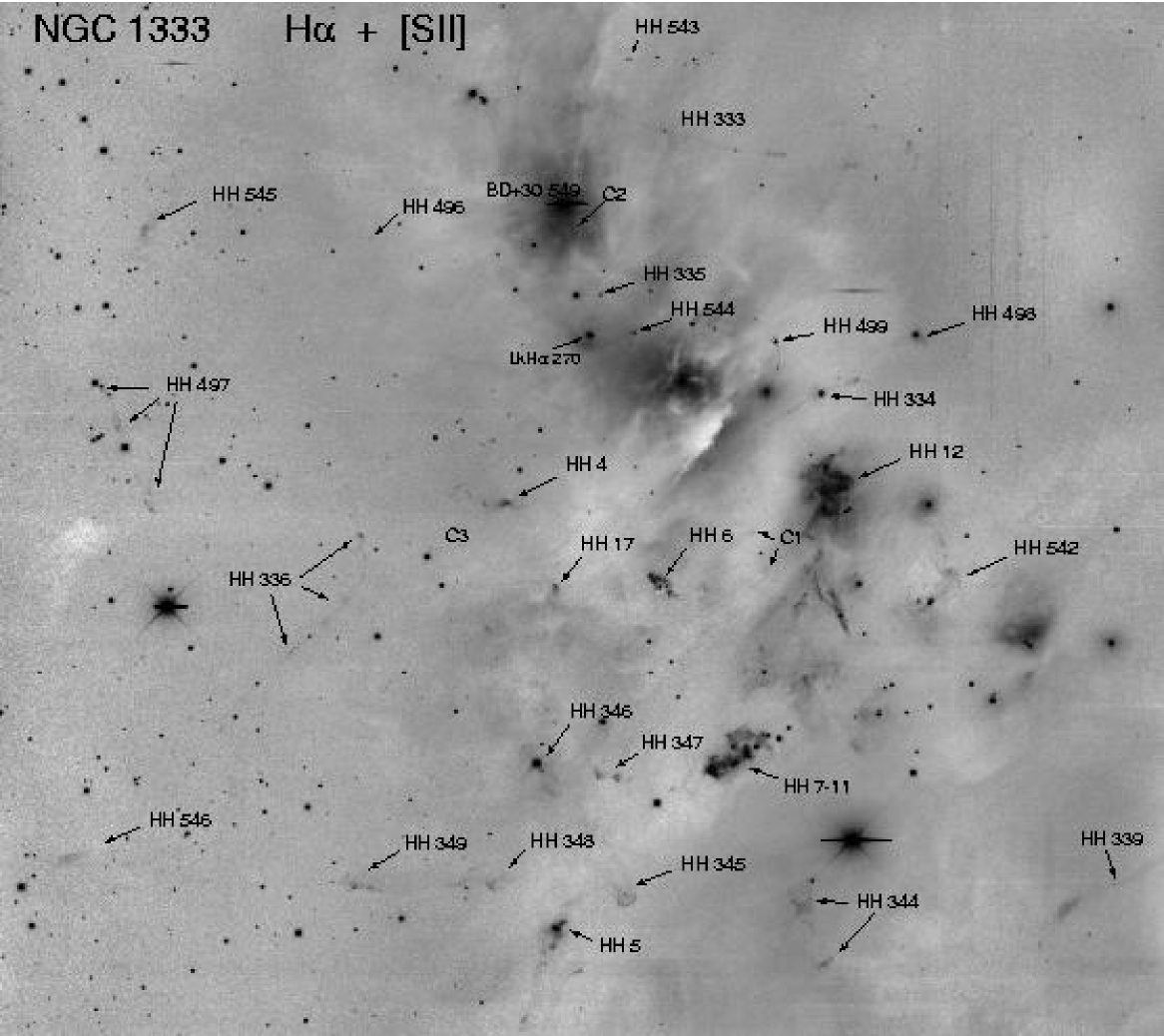
NGC 1333 (Figure 7) is the most active current site of star formation within the Perseus molecular cloud complex located at a distance of about 220 to 350 pc (Herbig & Jones 1983; Cĕrnis 1990). We adopt 220 pc for the distance to NGC 1333. Though the designation NGC 1333 strictly applies to a reflection nebula located at the northern end of a dense molecular cloud core, it is generally applied to the whole active site of star formation that has spawned at least 150 stars within the last 2 million years (e.g. Lada, Alves, & Lada 1996), and we use it to designate this entire star forming region. There is a remarkable concentration of highly collimated stellar jets in the immediate vicinity (within 5′ radius) of the NGC 1333 reflection nebula. All of these jets appear to be powered by visible stars with very small amounts of visual extinction. The locations of objects discussed below are given with respect to LkH 270 in the middle of the NGC 1333 reflection nebula. This star is located 0.45′ west and 2.2′ south of the B9 star BD+30°549, the brightest star in NGC 1333. HH 334 through 336 were discovered by Bally, Devine, & Reipurth (1996). The objects HH 497 through 499 are new.
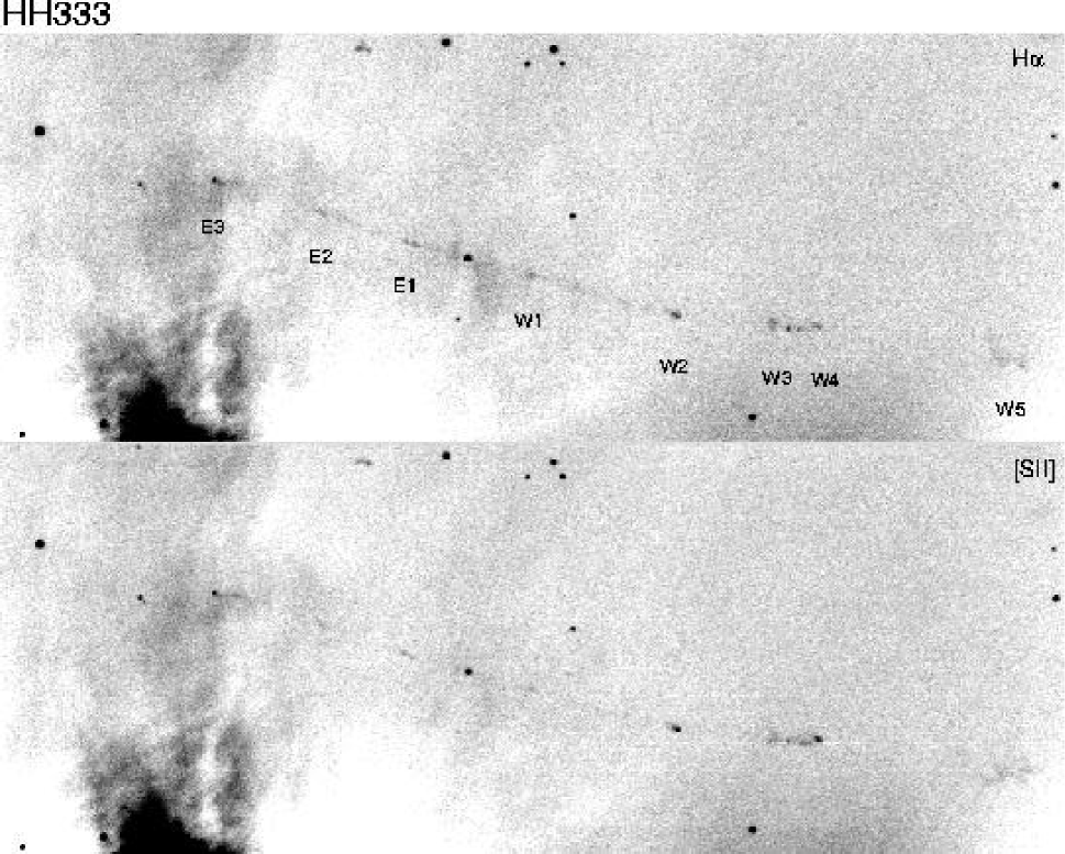
HH 333: A highly collimated jet emerges from an 18-th magnitude star 1.3′ west and 3.4′ north of LkH 270 at PA = 254° (Figure 8). The relatively bright [Sii] doublet towards the star implies an electron density at the base of the jet of cm-3. A faint H reflection nebulosity can be traced for up to 30″ from the source, especially on its southwestern side. The jet beam can be traced continuously on both sides of the central star for a total length of at least 3.5′ end-to-end. The jet remains remarkably straight and highly collimated within 70″ of the source (between knots E3 and W2). This section of HH 333 contains three nearly equally spaced knots on the east side (E1 – E3), and two knots on the west side (W1, W2) of the source. The knot pairs E1, W1 and E3, W2 are equidistant from the source; E2 does not appear to have an associated feature on the western side of the jet. The electron densities in knots E3 and W2 are 100 cm-3 and 160 cm-3, respectively.
Although the jet beam is unresolved, the knots E3 and W2 are about 2″ in diameter, implying that the jet remains confined to an opening angle less than 1.6°. Knots E1 through E3 are redshifted by about +50 km s-1, while W1 and W2 are blueshifted by about 50 km s-1. While the redshifted portion of the flow ends at knot E3, there are several additional diffuse bow shocks further along the jet axis towards the west. The beam appears to bend north at knots W3 and W4, and the fragmented bow shocks W5 and W6 continue in a further bending of the beam towards the north.
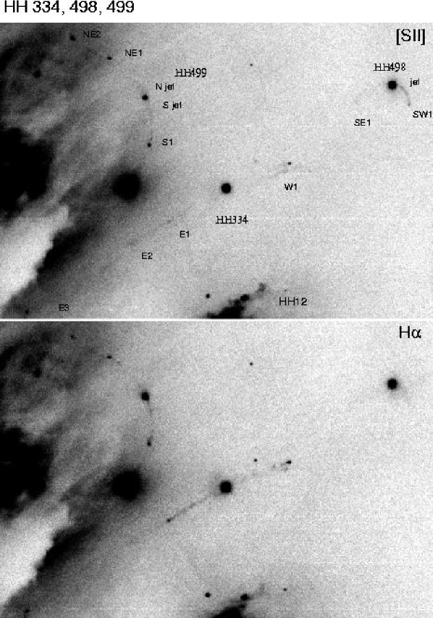
HH 334: This bipolar jet appears to originate from a bright H emission line star with EW(H) = 140Å located 3.9′ west and 1.0′ south of LkH 270 and north of the bright HH object HH 12 (Figure 9). The jet is knotty, and towards the west extends from the star at position angle PA = 290°, terminating in a bright H emission line knot, HH 334 W1. Several arc seconds to the south of this knot and of the main body of the jet, there is a parallel strand of [Sii] emission. The eastern portion of the HH 334 jet emerges from the star at PA = 120°, which deviates by about 10° from the orientation of the western jet. The eastern jet is H bright until it reaches the first knot E1, which is placed symmetrically with respect to W1 about the suspected source star. Beyond E1, the jet becomes a [Sii] bright filament that appears to terminate in a complex of knots about 1′ to the southeast of the source star.
The spectra show that both W1 and E1 are low velocity features with Doppler shifts of only +25 km s-1 for knot W1 and 25 km s-1 for knot E1. However, faint H emission can be traced to about +50 km s-1 in knot W1 and the line appears to be at least 50 km s-1 wide at low levels. Knot W1 is also quite bright in [Nii] and faintly visible in [Oi].
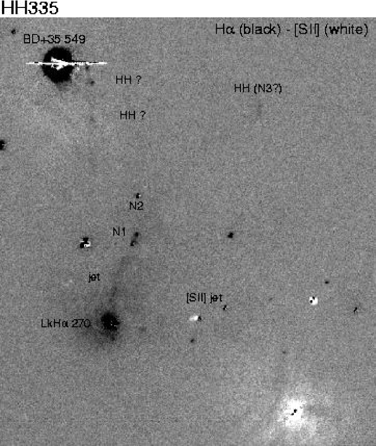
HH 335: HH 335 (Figure 10) is a monopolar bent jet which is nearly 1′ long and which is deeply embedded in the bright reflection nebula surrounding the star LkH 270 in NGC 1333. Therefore, it is best seen in the continuum subtracted images. The jet contains several knots along its length and gets progressively fainter with increasing distance from the apparent source. At its base, the jet is aligned with the axis of symmetry of the reflection nebula and is propagating nearly due north. However, the jet bends westward in a graceful arc by about 25° at its northern end.
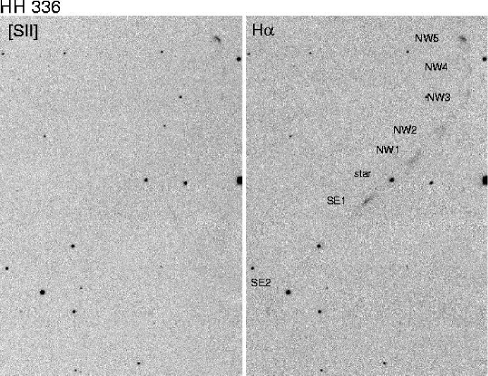
HH 336: This is a remarkable bipolar jet located symmetrically about an H emission line star to the east of the main NGC 1333 cloud core 4.7′ east and 5.1′ south of LkH 270 (Figure 11). The jet consists of several distinct segments separated by emission free gaps that emerges from the star at PA = 135° or 315°. The northwestern jet segments appear to be more diffuse and extended orthogonal to the jet axis with the second segment resembling a bow shock. The first southeastern jet segment is narrower and brighter than the corresponding northwestern segment. However, the area-integrated fluxes of the first jet segments are about the same. About 1′ from the source, the jet exhibits an abrupt bend towards PA = 10° in the northwest region and towards PA = 190° in the southeast region of the jet. The portion of the jet beyond the northwest bend is relatively brighter in [Sii]. The spectra show no measurable Doppler shifts, in either H or [Sii], although the line widths in H are about 70 km s-1. The H, [Nii], and [Sii] lines do show a slight velocity gradient across the source star with a roughly 20 km s-1 blueshift to the north and a comparable redshift to the south. These results imply that the jet lies very close to the plane of the sky with the northern beam pointed slightly towards us.
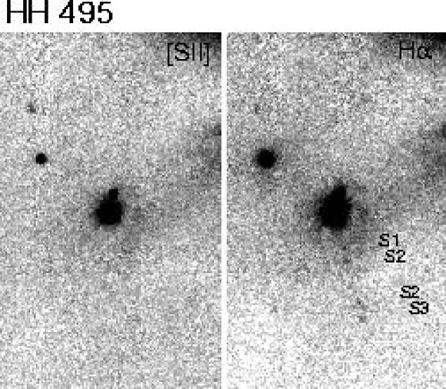
HH 495: This faint jet, located several arc minutes west of HH 7-11 and HH 12, consists of 4 faint H knots extending south from a faint star (Figure 12).
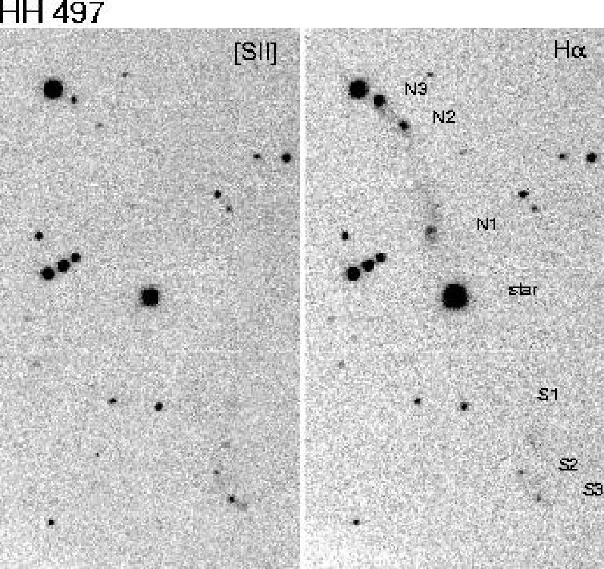
HH 497: This S-shaped flow (Figure 12) is centered on a bright star 3.2′ east and 3.1′ north of HH 366 at the eastern edge of NGC 1333. The southern side of the flow curves west and is bright in [Sii] while the northern side curves east and is bright in H (Figure 13).
HH 498: A curved filament of [Sii] emission emerges from a bright optical star about 5.5′ due west of LkH 270 (Figure 9). A very faint counter jet is also seen. If this feature is indeed a bent jet, it is the most extreme case found so far. The bending angle is 40° on the bright side of the jet and about 35° of the faint side. The southern portion of the jet fell in the slit used to observe HH 334. The radial velocity of the gas here is about +30 to +50 km s-1.
HH 499: This remarkable bent jet originates from an H emission line star (EW[H] = 138Å) located 3.1′ west and 0.1′ south of LkH 270, about 2.5′ north of HH 12 (Figure 9). A nearly continuous, but bent filament of H emission emerges from both sides of the star and ends in a knot of emission (HH 499 S1) 30″ south of the star. The filament is about twice as bright on the southern side of the star as on the north side. On the north side of the star, the filament bends towards a knot located 35″ northeast of the star (HH 499 NE1) and can be traced faintly to a second knot, NE2, located another 25″ away. The projected bending angle of the jet as measured from the star and original jet orientation is about 20°.
The spectra show that the southern (brighter) side of this jet is redshifted by about 50 km s-1 with faint wings extending up to +100 km s-1. The fainter counter jet is hard to see in the spectra, but appears to have a velocity of about 75 to 100 km s-1 with faint wings extending up to 125 km s-1. Both knots S1 and NE1 have predominantly redshifted emission with velocities ranging from +25 to +50 km s-1.
4 Discussion
It has become increasingly well documented that most stars are born in very high density and clustered environments. Both the Orion Nebula and NGC 1333 contain a few relatively massive stars which flood their environment with ultraviolet radiation. The Trapezium cluster contains at least six stars with spectral types earlier than O9.5 which produce a Lyman continuum ( 912Å) luminosity of about L(LyC) = photons s-1. The NGC 1333 reflection nebula is illuminated by several late B type stars with the most massive member, BD+30° 549, classified as B9. Unlike the Orion Nebula, there is no Hii region in this star forming region. However, there is an intense soft UV radiation field (912Å 2000Å) that can radiatively heat surrounding gas.
In externally irradiated outflow systems, the young stars powering outflows are frequently directly visible without significant obscuration. Either these stars are older than the usual sources of HH flows, or the surrounding cloud core has been prematurely eroded, possibly by the action of the external radiation field.
4.1 Exposing the Sources; Photo-Evaporation of Cloud Cores and Envelopes
In a star forming environment containing O and early B type stars, Lyman continuum radiation will ionize cloud surfaces and raise the temperature, pressure, and sound speed in the photon dominated layer. Mass loss occurs from the cloud if the sound speed in this layer exceeds the gravitational escape speed. The Lyman continuum flux incident on a cloud surface is , where is the Lyman continuum luminosity and is the distance of the cloud from the illuminating source. For a spherical cloud supporting a steady state outflow through a D-type ionization front at a radius the electron density at the base of the ionized flow is roughly where is the recombination coefficient. This formula assumes that the outflowing plasma has spherical divergence, a roughly constant outflow speed, and that the ionizing radiation field is absorbed in a shielding layer with a thickness comparable to the cloud radius. It is assumed that mass loss occurs from the illuminated hemisphere only. Since the flow leaves the ionization front at about the sound speed , the mass loss rate of freshly ionized plasma from the cloud surface is where is the mean molecular weight, mH is the mass of hydrogen, is the ionization front radius, and is a number of order unity which depends on the exact geometry and velocity profile of the accelerating flow (= 1/3 for a constant velocity spherical flow). Thus,
However, even in the absence of ionizing radiation, the soft UV between = 912Å and about 2000Å will heat the cloud surface layers. At the base of the irradiated region, the heated layer can reach temperatures of 100 to over K, where the speed of sound is about 1 to 3 km s-1 (cf. Hollenbach & Tielens 1997, 1999; Johnstone, Hollenbach, & Bally 1998). Therefore, soft-UV irradiated gas can expand from the heated surface so long as the local gravitational escape speed is less than the speed of sound, or where (the so-called gravitational radius cf. Hollenbach et al. 1994; G is Newton’s gravitational constant and is the total mass inside radius ). For a star plus circumstellar environment with a combined mass M (in Solar units), photo-erosion is likely to occur at distances larger than about 1779 M AU from the central star where the sound speed at the irradiated surface, , is in units of km s-1. Therefore, any residual envelope that may be left over from the formation of a low mass star will be dissipated if UV radiation raises the sound speed at the cloud surface to more than the gravitational escape speed.
The time-scale for the evaporation of the residual envelope can be estimated by assuming that this soft UV radiation is absorbed within a layer with a column density of cm-2, the penetration depth of this radiation (cf. Hollenbach & Tielens 1997). In the approximation that this flow diverges spherically, the base of the heated layer attains a density where is the cloud radius. If the actual gas density at radius is less than , the photon dominated region will advance into the cloud supersonically until a region with a density greater than is encountered. However, in this higher density environment, the PDR heated front will advance sub-sonically; outside the transition from shielded to irradiated gas, a roughly steady state outflow is established. In this scenario, the early transient stage is analogous to R-type ionization fronts while the later quasi-steady state is analogous to D-type ionization fronts. If the gas density at the cloud surface is initially larger than , the heating front will advance into the cloud sub-sonically. Once steady-state flow is established, the density at the base of the flow will be given by . The mass loss rate is given by so for typical parameters,
When ionizing radiation is present, the softer UV penetrates about a distance corresponding to into the cloud beyond the ionization front. Thus a PDR flow is established and may push the ionization front to a somewhat larger radius determined by the conditions of photoionization equilibrium as shown by Johnstone et al. (1998),
The approximate survival time-scale for an envelope surrounding a young star is given by
where is the total envelope mass and is the mean column density through this envelope. For typical core parameters ( = = 0.1 pc; = = 3 km s-1; = = 1022 cm-2), M⊙ yr-1, and years.
Cloud cores and envelopes can often be represented by power-law radial density profiles of the form . It can be shown that for mass loss controlled predominantly by the PDR, the cloud radius evolves with time according to
where and and is the initial mass of the power-law envelope inside radius . As an example, for a power-law index of , and an initial envelope mass of 1 M⊙ inside a radius of 0.1 pc, the envelope is completely destroyed in years for a PDR sound speed of 3 km s-1. A uniform density cloud () with these parameters evaporates completely in years. Thus, envelope evaporation is rapid and insensitive to the details of the cloud structure.
For mass loss controlled predominantly by Lyman continuum radiation,
where and is the distance from the source of ionization. For the parameters used above, complete envelope ionization is somewhat slower, taking about years for the uniform density case.
While the dissipating envelopes surrounding young stars in NGC 1333 are expected to remain predominantly neutral, within the Orion Nebula and its photo-ionized environment, the expanding envelopes will pass though an ionization front to form bright expanding condensations within the body of the Hii region. In the Orion Nebula proplyds, mass loss is sustained by the continued photo-evaporation of dense circumstellar disks at mass loss rates of about M⊙ yr-1 (Johnstone, Hollenbach, & Bally 1998). Since these disks are much smaller than the cloud cores considered above (100 AU vs. 0.1 pc), their mass loss rates are correspondingly much lower. The heating, expansion, and removal of lower density material will decrease the extinction and render visible the immediate circumstellar environment, including the young stars, their jets, and winds.
Dissociation, heating, and photo-evaporation by the soft UV radiation fields of nearby massive O, B, and even early A stars may play a major role in destroying the envelopes from which young stars accrete, thereby bringing further stellar growth to a halt. Since irradiated jets appear to be associated with naked young stars, their presence may signal one method by which Nature regulates the final masses of stars, namely the termination of accretion by external photo-evaporation. Furthermore, the photo-evaporative flows may play a fundamental role in the origins of turbulent motions inside molecular clouds (Bally et al. 2000a).
4.2 The Utility of Irradiated Jets
The launching of a high velocity wind or jet requires a reservoir of mass in the circumstellar environment to fuel the outflow. Most likely, this reservoir is in the form of a compact high density circumstellar disk surrounding the star. The sources of the irradiated jets must be in an evolutionary state where they have lost their envelopes (since the stars suffer low extinction) but still retain a substantial disk (since they power an outflow).
When such an outflow or jet is irradiated from the outside, the radiation field can dramatically improve the visibility of the moving fluid both in and far from the shock zone. Therefore, as noted by Reipurth et al. (1998), Herbig-Haro flows embedded within Hii regions provide a unique opportunity to determine completely the physical parameters of an outflow. Ionizing radiation in such an environment can partially or fully ionize all or most outflow components. In this situation, shock waves are not required to render the gas visible. Raga et al. (2000) present a more complete discussion of the propagation of ionization fronts into externally irradiated cylindrical jets.
Even when Lyman continuum radiation is not present, the softer UV radiation can enhance the visibility of the outflow. Photo-electric heating resulting from the interaction of the soft UV radiation field with grains in the medium produce extended regions that are bright in the optical forbidden lines such as [Sii].
4.3 Photo-Ionization of Irradiated Jets
Assume that the jet is launched with a steady ejection velocity, and prior to being irradiated can be characterized by a constant sound speed along its length, . These assumptions imply that the jet, if permitted by the ambient medium, will spread orthogonal to its direction of propagation at the Mach angle, so that the radius of the jet, , as a function of distance from the source, , increases as . If the mass loss rate into this lobe of the jet is given by , the mean density along the jet decreases as
Now consider a source of Lyman continuum radiation illuminating this jet so that the angle between the jet outflow axis and the direction to the illuminating star is given by an angle . If the jet points away from the ionizing source, it will initially be shadowed by the circumstellar disk. Once the jet emerges from this shadow the incident flux of Lyman continuum radiation is given by
where is the total opacity of the medium between the source of Lyman continuum radiation which is assumed to be at a distance from the portion of the jet under consideration.
Under most conditions, an R-type front will propagate rapidly into the side of the jet facing the illuminating star. However, Raga et al. (2000) show that under some conditions the front can also start out as a D-type front. If the jet has a sufficiently low density, it will become fully ionized by the incident radiation field. On the other hand, for a sufficiently high density jet, recombinations in the photo-ionized layer will slow the advance of the R-type front, eventually converting it into a D-type front. However, the gradual divergence of the jet guarantees that even in this latter case, as the distance from the jet source increases, an ever increasing portion of the jet will become ionized until the whole jet is fully ionized. In either case the degree of penetration of the ionizing radiation depends on the azimuthal angle about the jet axis. Penetration is greatest on the side of the jet facing the ionizing source, and least on the side facing away from the source. Back-side ionization is produced by the diffuse radiation field present in the Hii region and is therefore sensitive to the detailed spatial and density structure of the Hii region.
Ionization will raise the plasma temperature of the jet to about 6,000 to 10,000 K for normal (Solar) abundances. Because the sound speed in the neutral shielded portion of the jet is likely to be less than the sound speed in the ionized plasma, photo-ionization will likely increase the divergence (Mach) angle of the jet. In the ionized region, the transverse expansion orthogonal to the jet axis will occur at about a velocity of , the sound speed in the photo-ionized medium.
The incident Lyman continuum radiation is completely consumed by recombining ions and electrons in a layer of plasma with a thickness where is the electron density at the ionization front. If at the point where the jet emerges into the irradiated zone, , then the jet is in the low density limit and it will become fully ionized as the R-type front races through the thickness of the jet. If , the jet is in the high density limit and full ionization will be regulated by the divergence of the jet at the Mach angle.
For a dense jet, setting leads to a an estimate of the maximum distance from the source of the jet at which a neutral core can exist, . Beyond this distance, the jet will be fully ionized. Therefore,
This assumes that the radiation field is symmetric about the jet axis and that the core is ionized at the same rate in all directions. In general, the radiation field will be much stronger on one side of the jet and the shadowed side will become ionized more slowly. Highly asymmetric ionization can increase by about a factor of 2. For symmetric illumination, , = 200 km s-1, = 10 km s-1, = 3 pc, = M⊙, and 0.5, we find cm and the density of the jet at is . This corresponds to about 4000 AU or 0.02 pc, which is short compared to most HH jets.
Most Herbig-Haro flows are episodic. The shock waves associated with internal working surfaces, formed where faster ejecta overtake slower moving material, make portions of the jet visible. The four irradiated jets investigated by Reipurth et al. (1998) in the Orionis region exhibit relatively strong [Oi] and [Sii] emission (compared to H) close to the source where the jet is either shielded from external ultraviolet radiation or still retains a neutral core. This forbidden line emission originates in compact knots which likely trace internal working surfaces within the body of the jet. The brightest Orionis jet, HH 444, is associated with several nested bow shocks located more than 1 arc minute from the source. These features provide evidence that irradiated jets are also likely to be powered by time variable mass loss.
The episodic mass loss produces jets with density variations along their lengths. Furthermore, internal working surfaces and complex shock structures will form where faster ejecta overtakes slower ejecta supersonically. Internal working surfaces can produce line emission in the shielded portion of the jet. When low excitation shocks dominate excitation, the resulting emission will be dominated by the forbidden emission lines of neutral and low ionization states of common species like [Oi], [Sii], and [Nii]. As such a jet emerges into the external radiation field, the outer layer of the outflow will become ionized and the interior will be heated by the FUV radiation field. Thus, the jet skin will develop an Hii region spectrum while the shielded jet interior will exhibit enhanced forbidden line emission due to the heating by the FUV radiation. However, divergence of the flow insures that eventually, the entire jet becomes photoionized and will therefore produce an Hii region spectrum. Internal working surfaces within the jet will alter the density distribution. High density regions may be self-shielded and may retain mostly neutral cores for a much longer time than the lower density regions. Thus, episodic behavior and variations in the jet ejection velocity will generate clumps and complex structure in the irradiated portion of the jet. However, external ionization of these structures will render all moving fluid elements visible on deep images.
4.4 Asymmetries in Irradiated Jets
The four irradiated jets discovered by Reipurth et al. (1998) in the Orionis sub-group of the Orion OB association are predominantly one sided. The brightest portions of these outflows point away from the hot star. Preliminary spectroscopic evidence (cf. Bally et al. 2000b) indicates that for the jets near Ori, the brighter jet beams often have lower speeds than fainter counter jets. Therefore, the apparent asymmetry in jet intensity may be a consequence of an underlying kinematic asymmetry, possibly produced by the radiation field. The radiation field may preferentially decrease the density of matter on the irradiated side of a disk more than on the shadowed side. As an otherwise symmetric jet (both beams have the same mass loss rates and speeds) propagates through such an asymmetric medium, it may suffer more mass loading on the denser shadowed side than on the less dense irradiated side. This is especially true if mass loading primarily effects the skin of the jet, as it is the skin that is first ionized. Such mass loading could decelerate the jet motion through the shadowed side more than on the irradiated side.
Bally et al. (2000a) discuss over 20 irradiated microjets embedded within the core of the Orion Nebula which were discovered on deep high resolution Hubble Space Telescope images. The majority of these jets are also asymmetric with a slight tendency for the brighter beam to face the dominant source of the UV radiation. Hirth et al. (1997) found that many microjets produced by T-Tauri stars appear to be one sided; some show a kinematic asymmetry with one beam having a larger velocity.
All five outflows reported here in the outskirts of the Orion Nebula, HH 502 – 506, are also asymmetric. Although both HH 502 and 503 contain bow shocks on either side of the source, indicating that mass loss is bipolar, the jets in both of these sources are more prominent on the side of the source facing away from the source of Lyman continuum radiation. Though jets are visible on the opposite side of the source that faces into the radiation field, they tend to be much fainter and shorter.
As discussed by Reipurth et al. (1998), extinction can be ruled out as an explanation for the asymmetry of the Orionis jets. Similar arguments can be used to rule out extinction as the explanation for the asymmetries of the jets located in the Orion Nebula. The nebular background is sufficiently bright so that any extended absorbing cloud would be seen in silhouette. Furthermore, in the two jets where bow shocks are seen on both sides of the central source, these shocks have similar surface brightness, indicating that there is little difference in extinction on the two sides of the source.
The preliminary evidence suggests that the Orion jets exposed to Lyman continuum radiation are often one sided. On the other hand, the irradiated jets in NGC 1333, which are exposed to weaker and softer UV radiation fields, tend to exhibit bipolar symmetry.
4.5 The Origins of Jet/Counterjet Brightness Asymmetry in Irradiated Outflows
In this section, two models of bipolar jets which can produce the observed asymmetries in irradiated jets are discussed. It is assumed that the jet is intrinsically bipolar with the same mass loss rate, , into each beam. However, the velocity with which each beam moves away from the source, , is assumed to be different for each beam. As discussed above, different amounts of mass loading in each beam may produce such kinematic asymmetry.
In the first model, case A, the opening angles of the lobes of the bipolar jet are assumed to be the same. Lobes of a bipolar jet may expand into cones having the same opening angle if jet spreading is dominated by external processes such as a high pressure external medium or one that contains a strong magnetic field. In kinematically asymmetric bipolar jets with a constant beam opening angle the slower beam is brighter. In the second model, case B, the speed at which jet material spreads orthogonal to its bulk motion is assumed to be constant. Therefore, the opening angle of the jet is inversely proportional to the jet speed. This situation is likely to prevail if the transverse expansion of the jet is determined by internal processes such as heating by a radiation field so that each beam expands at the sound speed into a Mach cone. Alternatively, if the amplitudes of the velocity variations producing internal shocks are the same in each beam, splashing of jet material orthogonal to the jet axis may occur at a fixed velocity. In kinematically asymmetric bipolar jets with a constant transverse spreading, the faster beam is brighter.
Other, more complex models, which will not be discussed here in detail, are also possible. For example, if the kinematic asymmetry is generated at the source rather than by mass loading, the faster outflow lobe might also have time-variability with a larger velocity amplitude. This would produce stronger shocks, and denser shocked material, which would result in a brighter jet beam.
Case A: Bipolar Jets With a Constant Opening Angle
Consider a bipolar jet in which both lobes have the same opening angle, . Furthermore, assume that the mass loss rates into each beam are identical, and that the beams have different velocities. Therefore, at a given distance from the source , the jet radii, will be the same. However, the continuity equation implies that if the mass loss rates, , into each beam are the same, the density of matter in the jet, , will be higher in the slower beam than the corresponding density at the same distance from the source in the faster beam.
The surface brightness of an emission line scales as the emission measure, , where is the path length of the observer’s line-of-sight through the emission region. Therefore, for a fully ionized bipolar jet which has the same opening angle in each beam, the faster beam will appear fainter by a factor . In general,
When the contrast between the Hii region and the jet is low, the fainter jet can altogether vanish from view.
Case B: Bipolar Jets With Constant Transverse Spread
On the other hand, if the jet lateral spreading occurs at a constant transverse velocity, , each beam of the jet will exhibit a similar density and emission measure at a comparable dynamical age as opposed to at a comparable distance from the source. Because the opening angle is given by , the faster beam will have a narrower opening angle and higher density at a given distance from the source. Using this definition of in the formula above, the emission measure is found to scale as
Thus, for the case where the opening angle is defined by a constant transverse velocity, the faster beam will exhibit the greater surface brightness at a given distance, a prediction opposite to that of a constant opening angle jet.
In summary, if external processes dominate jet expansion, and the opening angles of each lobe are the same, then at a given distance from the source, each beam will have the same transverse extent (Case A). The slower beam will then be denser and brighter. Alternatively, if internal processes such as splashing from internal working surfaces or heating by a radiation field dominate the transverse spreading of the jet, each lobe is likely to expand at the same transverse velocity (Case B). When the jet speeds are not the same, the slower beam will exhibit a wider opening angle. Therefore, at a given distance from the source, the faster beam will be narrower, denser, and brighter. High dispersion spectroscopy and imaging will be able to distinguish between these different scenarios and probe the generality and origins of kinematic asymmetry.
4.6 Jet Density Estimation for Irradiated Jets
The H surface brightness can be used to estimate the emission measure, EM, of a jet from the relationship where is in units of (Spitzer 1978). If the extent of the jet along the line-of-sight is assumed to be the same as the projected width of a feature, the emission measure can be used to estimate the electron density of the plasma within the jet from the relation where is the path length through the emission feature. These quantities are tabulated in Table 3 along with the surface brightness of the [Sii] emission from the same features and the H to [Sii] surface brightness ratio for a selected set of points in the major detected features of each flow. The listed values correspond to the peak surface brightness in each region, and therefore yield upper bounds on the line intensities and derived electron densities.
If the jet is fully ionized by the external radiation field the derived plasma density is the jet density, which can be combined with measurements of the jet velocity to estimate the mass loss rates into each beam, the momentum, and energy fluxes. The flow momentum and energy can be estimated from the density, the flow cross-section, and the fluid velocity. For a cylindrical flow with radius , density , and velocity , the mass loss rate in the jet, or equivalently the rate at which mass flows through a given stationary surface, is given by . In terms of this quantity, the flux of momentum and kinetic energy are and . Thus, for a jet speed of in units of 100 km s-1, a jet density in units of , and a jet radius in units of 115 AU (which corresponds to our seeing deconvolved resolution limit in Orion), the jet has a mass loss rate M, a momentum transfer rate of M, and a mechanical luminosity of L⊙. Table 4 summarizes the mechanical parameters of the photo-ionized portions of the flows in the Orion Nebula.
The extent to which the jet is ionized can be estimated by comparing the observed emission measure to that of a self-shielded cylinder of neutral gas. If the jet contains a shielded neutral core with a radius , and is located at a distance from a source of Lyman continuum radiation with luminosity , then photo-ionization equilibrium in the shielding layer implies that
where is a factor of order unity which takes into account the relative orientation of the jet, the line of sight to the illuminating star, and the geometric divergence of the expanding plasma. Thus, the emission measure is given by
where photons per second is the Lyman continuum luminosity of the Trapezium, and is in parsecs. The inner portion of the HH 502 and 503 jets and some of the brighter knots in the HH 502 bow shocks are only a factor of 4 – 10 lower than this maximal emission measure. Thus, these portions of the flow are likely to be only partially ionized with a shielding layer that protects a neutral core from the Lyman continuum radiation. Thus, the mass loss estimates and other parameters listed in Table 5 may well be lower limits.
On the other hand, finite angular resolution may result in an overestimate of the jet mass loss rate. Near their sources, the Orion Nebula jets are essentially unresolved in width. Thus, the jet width used in the estimation of mass loss rates is assumed to be at the seeing-deconvolved resolution limit of about 0.5″, corresponding to a jet radius of 115 AU. If the jet radius is actually smaller, the estimated electron density in the ionized region increases as , and the resulting jet mass loss rate declines as . Thus, higher angular resolution measurements of both the jet ionization structure and its width, and a combination of proper motion measurements and more precise radial velocity determinations are needed to better constrain the jet parameters and to take full advantage of the ionized nature of these outflows.
4.7 Why Are Irradiated Jets Highly Collimated?
HH 502 in Orion (Figure 2) and HH 333 in Perseus (Figure 8) are the longest jets discussed here. And they are both extremely collimated. The beams of these jets remain less than two arc seconds in diameter at distances larger than 40″ (for HH 502) and 120″ (for HH 333) from their respective sources. Thus, these jets remain collimated to within a few degrees or less. Such a high degree of collimation is even more surprising in the light of the low radial velocities measured for these jets.
In an externally photo-ionized jet such as HH 502 or HH 503, the sound speed in the jet interior should be about 10 km s-1. If the intrinsic jet speed is assumed to be 100 km s-1, then the Mach angle is predicted to be about 6°, and the jet opening angle should be about 12°, many times larger than the apparent opening angles of HH 502 or HH 503. There are three possible reasons why these jets may appear so collimated.
First, these jets may lie nearly in the plane of the sky, in which case their true velocities may be many times the observed radial velocity. However, to produce a less than 3° opening angle, the speed of the HH 502 or HH 503 jets would have to exceed 300 km s-1.
Second, it is possible that the jet is so dense that only a thin surface layer becomes ionized throughout its visible length. Thus, the jet density estimates based on the emission measure may be strict lower limits. In this scenario, the jet interior may remain sufficiently shielded and cold so that the Mach angle remains very small and the jet does not spread. However, to explain the fading or disappearance of the beam, the beam must come to an end at some distance from the source. A time-variable outflow would produce segments of ejecta separated by relatively empty gaps. Perhaps the apparent ends of these jets correspond to the beginning of the gaps produced by lower mass loss rates in the past. The bow shocks seen downstream of the apparent ends of jets such as HH 333 and HH 502 may trace the debris piled up by earlier high mass loss rate episodes that were followed by relative inactivity. This explanation is most likely to apply to the highly collimated irradiated jets in the Orion Nebula.
Third, there may be an invisible confining medium that prevents free expansion. Such a medium may consist of a dense but invisible gas, or a magnetic field. However, a dense confining medium in the Orion Nebula’s interior would be ionized and visible. So if confinement is invoked for Orion’s irradiated jets, then a magnetic field of sufficient strength must be present. However, in NGC 1333, a dense medium could remain invisible. But, its total dust content must not be sufficient to hide the jet. Additional observations are needed to decide which model is the best explanation for the high degree of collimation of the irradiated jets.
4.8 Origin of the C-Shaped Symmetry of Jets in H II Regions
Two distinct types of C-shape symmetry are observed in Orion and NGC 1333. All of the bent jets embedded within the Orion nebula bend away from the nebular core. On the other hand, the bent jets in the core of NGC 1333 tend to bend toward the cluster core.
There are three forces which can in principle deflect a jet propagating through the ionized interior of the Orion Nebula; ram pressure of the champagne flow of plasma from the nebular interior (), radiation pressure (), and the rocket effect of the jet shielding layer pushing on the jet neutral core ().
Evidence for a general, widespread outflow from the core of the Orion Nebula has been provided by high dispersion spectroscopy (O’Dell 1994; Wen & O’Dell 1993; O’Dell et al. 1993) and by the presence of stationary bow shocks formed where T Tauri star winds impact this outflow (Bally et al. 2000a). Though highly uncertain, the mass flux from the Orion Nebula core has been estimated to be in the range = to M⊙ yr-1 with a speed of order 20 km s-1. Bally et al. (2000a) interpreted the so-called LL Orionis wind-wind collision fronts in terms of a collision between wide-angle T Tauri stellar winds and the champagne flow from the Nebula. Table 5 lists additional wind-wind collision fronts located in the vicinity of the irradiated jets which provide evidence for such a bulk outflow of plasma from the Nebula. Although stellar winds from the hot Trapezium stars could also play a role, the product of the champagne flow is likely to exceed that of the massive star winds by more than an order of magnitude in the outer nebula. The effect of the champagne flow ram pressure is identical to the case of a jet propagating in a cross wind (cf. Raga et al. 1995).
The champagne flow ram pressure can be estimated from the mean density of the nebula near the bent jets, and its average flow velocity of slightly more than the sound speed in ionized gas. Thus, dynes cm-2 where is the plasma density in units of and is a factor of order unity. Radiation pressure is given by dynes cm-2 where is the luminosity in units of L⊙, is the opacity of the medium to incident radiation (most likely much less than 1), and is the distance from the light source in parsecs. Finally, for jets above the critical density, an ionized layer forms on the illuminated side of the jet. Its expansion pushes on the neutral jet core, deflecting it away from the light source by means of the rocket effect. The resulting pressure is given by where is the observed plasma density in the ionized portion of the jet (cf. Table 3). Typically, the jet surface layer is much more than an order of magnitude denser than the Hii region density in the vicinity of the jet. If this were not the case, the jet would not be visible against the background nebula since the path length through the jet is usually smaller than the path length through the nebula by more than three orders of magnitude. Once the jet becomes fully ionized (due to spreading at the internal Mach angle), the rocket effect disappears since the fully ionized jet plasma will expand symmetrically about its axis. The rocket effect is most effective in bending the jet when about half of the beam is ionized and the amount of bending expected is roughly which is just the Mach angle for a fully ionized jet. For the parameters appropriate for HH 502 to 505, . And the rocket effect is likely to dominate other external forces which can act directly on the jet beam.
However, it is possible that deflection of the jet cocoon also plays a role in bending these outflows away from the nebular core. The densest parts of these cocoons are traced by the various bow shocks associated with the Orion Nebula irradiated jets. However, these features are likely to be fully ionized and optically thin to incident radiation. Therefore, the only force capable of deflecting them is the ram pressure of the expanding nebula. Although capable of deflecting the cocoon walls downstream, the cocoon interior is shielded from this force. Such deflection of the cocoon may be responsible for making the upstream side of the HH 503 W1 bow shock be so close to the HH 503 jet. It also may be responsible for the LL Orionis type bow shock surrounding HH 505. However, if this was the only force acting on the system, the jet should propagate from the source without deflection until it impacts the deflected cocoon wall. But, our images of HH 502 and 503 show that the jets themselves are deflected. If the cocoon interior were sufficiently magnetized, it is possible that Alfvén waves in the cocoon interior could transmit the pressure applied on the cocoon walls to the jet, causing it to bend. However, it is more likely that the above mentioned rocket effect deflects the jet while the ram pressure of the champagne flow deflects the jet cocoon and the associated bow shocks. The observed deflection angles of both the jets and the jet cavity walls can be used to confront these theoretical ideas. As shown in Table 2A, the observed jet bending angles are of order 10°.
The true bending angle of a jet may be quite different from the observed bending angle due to the projection of the outflow onto the plane of the sky. Consider a bent outflow from a source assumed to lie at the origin of a Cartesian coordinate system. Assume that one beam of the outflow propagates in the direction. This jet and its counterjet define a plane in which the jet bending angle can be defined as the angle between a vector directed along the axis (along the expected direction of the counterjet in the absence of bending) and the counter-jet. The y-axis of the coordinate system is assumed to lie in the plane of the curved jet. The projection of the outflow onto the plane of the sky is described by two rotation angles, and , about the and axes, respectively. (In general, an additional rotation about the line-of-sight is also needed to align the jet or counter-jet with a specific orientation on the sky, but this rotation does not effect the projected jet deflection angle.) In terms of these two angles, the observed (projected) deflection angle, is given by
For example, if = 30° and = 60° the true bending angle is nearly a factor of two smaller than the observed (projected) bending angle. However, the inclination angles are unknown for the jets discussed here.
Cantó & Raga (1995) discuss the deflection of a jet by a supersonic side wind. In this model, the ambient medium interacts directly with the jet rather than a surrounding cocoon formed by sideways splashing of material colliding in internal working surfaces. The jet deflection angle, , is defined as the angle between the launch orientation and a line tangent to the jet at some point. For an isothermal jet with sound speed , this angle is given by
where and are the densities of the ambient moving medium and the jet, and are the velocities of the ambient medium and the jet (assumed to be initially perpendicular), is the distance from the jet source of the point where the jet bending is being measured, is the radius of the jet at that point, and is the Mach number of the jet. Given an observed deflection angle, this formula can be solved for , the relative motion between the jet source and the medium. For small angles, = 2 so that for typical inclination angles, the observed deflection angles (Table 5) can be directly used in the above formula. For km s-1, °, = 1/30,
Since the Orion jets are visible against the nebular background, they must be much denser than the surrounding medium. For cm-3 (Table 3) and cm-3 (a reasonable guess for the outskirts of the Orion Nebula), km s-1.
This velocity is about what is expected for either deflection of the jet by the rocket effect, or by the ram pressure of nebular champagne flow. If the ambient medium is interacting with the jet cocoon rather than the jet itself (as may be the case for HH 502 and 503), the density above should be that of the cocoon, which may be comparable to the ambient medium. In this case a considerably lower velocity side wind can deflect the flow. Thus, the C-shaped symmetry of the Orion Nebula irradiated jets may be produced by the combined action of the rocket effect acting on the ionized skins of the jets, and the ram pressure of the nebular champagne flow acting on the outer walls of the cavities created by the jets (the jet cocoons).
4.9 Origin of the C-Shaped Symmetry in Dense Clusters
There are two important differences between the jets embedded within NGC 1333 and those in the Orion Nebula. First, all bent jets in the Orion Nebula appear to lie at large projected distances from the cluster core. Most lie several parsecs from the Trapezium cluster, well beyond its dynamical influence. At this distance, the time scales for crossing the cluster at the expected stellar velocities are much longer than the ages of the observed HH flow components. In contrast, all of the bent jets in the NGC 1333 region lie within the projected boundaries of the embedded cluster. Second, the bent jets within the Orion Nebula are exposed to outward oriented forces such as the rocket effect and the low Mach number outflow of plasma from the nebula core. In contrast, there is no rocket effect or outflow of plasma from the NGC 1333 core since there is no H II region. The jets in NGC 1333 are only irradiated by non-ionizing soft-UV photons. This difference eliminates the bending mechanisms proposed for the irradiated jets in the Orion Nebula. Furthermore, it makes it conceivable that the bent jets in NGC 1333 result from recent dynamical interactions in the rich cluster of 150 stars packed into a region smaller than 1 pc in diameter.
C-shaped outflows can be produced when either the medium moves past the source of a bipolar jet, or the source moves through the medium. In the Orion Nebula, the former explanation plus the outward push of the rocket effect on the jet skin can explain the jet bending. However, the bipolar flows HH 334, HH 499, and HH 498 near NGC 1333 bend towards the core of the star cluster. For intrinsic bending angles comparable to the observed values, HH 334 requires a transverse velocity of about km s-1. However, HH 499 and HH 498 require transverse motions of km s-1 and km s-1, respectively. It is likely that HH 498 and 499 are seen nearly end-on so that projection effects greatly exaggerate the bending angle. Even so, these velocities are likely to exceed the gravitational escape speed from the parent cloud (a few km s-1) and cannot be produced by infalling gas. An alternative and more plausible scenario is that these three jet sources have been recently expelled from the cluster center by dynamical interactions such as the re-arrangement of non-hierarchal triple systems (cf. Sterzik & Durisen 1995; Reipurth et al. 1999 and references therein). For a 10 km s-1 stellar motion through the medium, the time since ejection from an interaction 0.3 parsec away (about the distance from the cluster core) is about 30,000 years. For an ensemble of 150 stars, three such interactions over the 30,000 years is required to produce the three C-shaped symmetric jets.
5 Conclusions
We report the discovery of five irradiated jets in the outskirts of the Orion Nebula (HH 502 through 506). Four of these jets are at least partially photo-ionized by the Lyman continuum radiation field of the Trapezium stars. All five jets exhibit C-shaped symmetry with jets and jet cocoons that bend away from the core of the Orion Nebula. All five jets are intrinsically asymmetric with one beam typically at least three times brighter than the counter jet. However, all jets do show evidence for being bipolar on larger scales.
New observations of nine soft-UV irradiated jets are presented, including five new discoveries (HH 495 – 499), near the reflection nebula NGC 1333 in Perseus. These flows are irradiated by the non-ionizing UV radiation field of B stars in the NGC 1333 cluster. They differ from most HH flows and jets in that their driving sources are visible at visual wavelengths and that both beams are plainly seen with relatively low obscuration. As is the case for the irradiated jets exposed to Lyman continuum radiation, the circumstellar envelopes of these young stars have been eroded, presumably by the soft UV radiation field.
A model of soft-UV induced cloud core and protostellar envelope erosion is presented. Apparently even non-ionizing radiation fields can expose the forming young stars and render their jets easily visible. Dissociation, heating, and photo-evaporation by soft UV may play a major role in destroying the envelopes from which young stars accrete, thereby bringing further stellar growth to a halt. Irradiated jets are associated with naked young stars. Their presence may signal one method by which Nature regulates the final masses of stars, namely the termination of accretion by external photo-evaporation caused by massive O, B, and even early A stars. The photo-evaporative flows may even play a fundamental role in the origins of turbulent motions inside molecular clouds.
A model for jet photo-ionization by Lyman continuum radiation is presented. Conical jets spreading with a finite opening angle become fully photo-ionized at some distance from the source. We discuss several mechanisms which can explain the observed asymmetries of the irradiated jets. Such asymmetries are likely to be produced by dissimilar mass loading of the jet and counter jet which can produce a kinematic asymmetry. The resulting velocity difference between the jet and counter jet can make either the fast beam brighter at a given distance from the source (if both beams spread at the same velocity orthogonal to the jet axis and thus have unequal opening angles) or can result in the slower beam being brighter (if the beams have the same opening angles).
The physical mechanisms that can bend jets are discussed. In the Orion Nebula, C-shaped bending is likely to be a result of the rocket effect acting on the skin of the jet while it is only partially ionized. However, the jet cocoons may also be deflected by the ram pressure of the champagne flow from the core of the nebula. If magnetized, the cocoons may also contribute to jet deflection.
Three of the NGC 1333 jets exhibit C-shaped symmetry with bending towards the cluster core. We argue that these stars may have been recently expelled from the cluster core by dynamical interactions and are now moving through the surrounding medium at about 10 km s-1.
Six new LL Orionis type wind-wind collision fronts are reported in the outskirts of the Orion Nebula.
6 Appendix 1: New Herbig-Haro Objects in Orion and NGC 1333
In addition to the irradiated jets, our imaging survey has revealed additional Hebrbig-Haro objects which were identified as emission line features with compact structure. Many, but not all, are most conspicuous in the [Sii] images. The HH numbers and positions of the objects are listed in Table 6 and a short description of each object is given below.
HH 547: A very bright [Sii] bow shock facing towards the west and located about 10′ west of the NGC 1333 cloud core. A faint envelope of emission can be traced back towards the east for about an arc minute on the south side of the bow.
HH 542: A complex of [Sii] knots and filaments that emerge from a reflection nebula located about half an arc minute to the southeast of the HH objects. The reflection nebula has an axis of symmetry at about PA = 315° and points towards the HH 542 complex.
HH C1: A pair of bow shaped H features located symmetrically on either side of an H emission line star. The bows face away from this star. A line drawn through the tips of the bows has PA = 10°. This is possibly an HH object.
HH 543: A small [Sii] knot located just north of the HH 333 jet. There is a hint of elongation along an east–west axis.
HH 544: A bright 5″ long [Sii] jet emerging towards PA = 100° from a faint star embedded within the NGC 1333 reflection nebula. Two knots are resolved with the knot closest to the star being the brightest.
HH C2: A chain of H knots at PA = 10° in the NGC 1333 reflection nebula. The chain is located directly west of the bright star BD+30 549 and is embedded in its bright reflection nebulosity. This is possibly an HH object.
HH C3: A faint 10″ long H filament emerging from a star at PA = 350°. This feature may be a very faint irradiated jet. There is a hint of a very faint counterjet. There is an additional very faint H filament located about 1′ south of HH C3 along the expected location of the couterjet. This feature also has an orientation of PA = 350°. This is possibly an HH object.
HH 496: A compact [Sii] knot and a faint filament connecting it to a star about 30″ to the northwest.
HH 545: A large and diffuse [Sii] bright bow shock facing east that is located about 7′ east of BD+30 549. The shock is about 30″ in diameter, has a sharp eastern edge, and a diffuse western side.
HH 546: A large but faint east-facing bow shock due east of HH 348 and 349 (Bally et al. 1996a). The shock can be traced for about 1′ in the east-west direction and has a sharp northern edge. This structure appears to be a continuation of the outflow traced by HH348/349. HH348, 349, and 546 may be powered by the deeply embedded infrared source IRAS 4B (Blake et al. 1995) which lies along the axis of symmetry of these HH objects.
HH 384: A 30″ long filament at PA = 100° in the OMC2 region. This object was discovered in the study of Yu et al. (1997) and Reipurth et al. (1998).
HH 532: A compact [Sii] bright HH object located about 30″ northwest of HH 506 several arc minutes north of M 43 and east of OMC2. The orientation and location of this bow shaped HH object suggests that it is unrelated to the nearby HH 506 irradiated jet.
HH 533: A 30″ long [Sii] filament oriented towards PA = 20° located in the OMC2 region. The morphology may be indicative of a jet.
HH 535: A bright 30″ long chain of compact bow shocks apparently propagating towards PA = 330° from OMC2. This collimated outflow appears to be aimed at HH 44 located several arc minutes to the northwest, and may represent either the driving jet, or a portion of the flow which excites that HH object.
HH 536: A cluster of faint [Sii] knots and arcs about 1′ northwest of a compact reflection nebula whose axis of symmetry points towards HH 536. If this association is correct, then this flow lies parallel to but slightly south and west of the HH 535/44 flow.
HH 537: This is the brightest new HH object in the survey fields, and one of the brightest HH objects in the sky. Lying at the northern periphery of the M 42 Hii region, this HH object has been missed because of the glare of the Orion Nebula. This bright bow shock appears to be propagating towards PA = 235° from the vicinity of OMC2 which is located about 7′ towards the northeast (projected distance of about 1 pc). HH 537 consists of a bright apex with a fainter and clumpy bow whose southern wing can be traced back for at least 1′.
HH 538: A bright but compact bow shock located a few arc minutes north of M 43. The morphology, which consists of a bright knot surrounded by several fainter clumps in the wings of a bow shock suggests that this flow is propagating towards the southwest.
HH 539: A faint emission line knot located about 1′ northeast of HH 538.
HH 540: A pair of bright bow shocks located south of the bright bar in the Orion Nebula. The shocks are separated north-south by about 40″. The flow appears to be propagating from an unknown source at PA = 200° towards the south.
HH 541: A [Sii] bright filament embedded within a complex filamentary nebula near the southern periphery of M 42 several arc minutes south of the HH 504 irradiated jet.
References
Bally, J., & Devine, D. 1994, ApJ, 428, L65
Bally, J., Devine, D., Fesen, R., & Lane, A. P. 1995, ApJ, 454, 345
Bally, J., Devine, D., & Reipurth, B. 1996a, ApJ, 473, 49.
Bally, J., Morse, J., & Reipurth, B. 1996b in Science with Hubble Space Telescope - II eds. P. Benvenuti, F. D. Macchetto, & E. J. Schreier, (STScI, Baltimore), p. 491
Bally, J., O’Dell, C. R., & McCaughrean, M. J. 2000, AJ (in press)
Bally, J., et al. 2000b, (in preparation).
Blake, G. A., Sandell, G., van Dishoeck, E. F. 1995, ApJ, 441, 689
Devine, D., Bally, J., Reipurth, B., & Heathcote, S. 1997, AJ, 114, 2095
Cantó, J. & Raga, A. C. 1995, MNRAS, 277, 1120
Cĕrnis, K. 1990, Ap&SS, 166, 315
Chernin, L. & Masson, C. R., Pino, E. G. D., & Benz, W. 1994, ApJ, 426, 204
Cernicharo, J., et al. 1998, Science, 282, 462
Gull, T. R., & Sofia, S. 1979, ApJ, 230, 782
Hartigan, P., Morse, J. A. & Raymond, J. 1994, ApJ, 436, 125
Herbig, G. H., & Jones, B. F. 1983, AJ, 88, 1040
Hillenbrand, L. A. 1997, AJ, 113, 1733
Hillenbrand, L. A. & Hartmann, L. W. 1998, ApJ, 492, 540
Hirth, G. A., Mundt, R., Solf, J. 1997, A&AS, 126, 437
Hollenbach, D. & Tielens, A. G. G. M. 1997, ARAA, 35, 179
Hollenbach, D. & Tielens, A. G. G. M. 1999, Rev.Mod.Phys. 71, 173
Hollenbach, D., Johnstone,, D., Lizano, S. & Shu, F. H. 1994, ApJ, 428, 654
Johnstone,, D., Hollenbach, D., & Bally, J. 1998, ApJ, 499, 758
Lada, C. J., Alves, J., & Lada, E. A. 1996, AJ, 111, 1964
Masson, C. R., & Chernin, L. M. 1993, ApJ, 414, 230
McCaughrean, M. J. & Stauffer, J. R. 1994, AJ, 108, 1382
O’Dell, C. R. 1994, Ap&SS, 216, 267
O’Dell, C. R., Valk, J. H., Wen, Z. & Meyer, D. M. 1993, ApJ, 403, 678
Wen, Z. & O’Dell, C. R. 1993, ApJ, 409, 262
Raga, A., López-Martín, L., Binette, L., Loṕez, J. A., Cantó, J., Arthur, A. J., Mellema, G.,
Steffen, W., & Ferruit, P. 2000, MNRAS, 314, 681.
Raga, A, & Cantó, J. 1989, PASP, 111, 1964
Raga, A., & Cabrit, S. 1993, A&A, 278, 267
Reipurth, B. 1999, A General Catalogue of Herbig-Haro Objects, 2. Edition, published electronically at http://casa.colorado.edu/hhcat
Reipurth, B., Bally, J., & Devine, D. 1997, AJ, 114, 2708
Reipurth, B., Bally, J., Fesen, R., & Devine, D. 1998, Nature, 396, 343
Reipurth, B., Yu, K. C., Rodríguez, L. F., Heathcote, S., & Bally, J. 1999, A&A, 352, L83
Sterzik, M. F., & Durisen, R. H., 1995, AA, 304, L9
Yu, K. C., Bally, J., & Devine, D. 1997, ApJL, 485, 45
| Table 1: Journal of Spectroscopic Observations | ||||
| Object | HH | Date | PA | Comments |
| (°) | ||||
| NGC 1333 | 333 | 1/11/96 | 74 | 3 500s |
| NGC 1333 | 334 | 12/27/98 | 115.7 | 3 600s |
| NGC 1333 | 336 | 1/11/96 | 135 | 3 1000s |
| NGC 1333 | 499 s1 | 12/27/98 | 25 | 3 600s star+jet |
| NGC 1333 | 499 s2 | 12/27/98 | 25 | 3 600s knots NE1 and S1 |
| M42 | 502 s1 | 12/27/98 | 22 | 2 100s |
| M42 | 502 s2 | 12/27/98 | 40 | 2 100s |
| M42 | 502 s3 | 12/27/98 | 7 | 3 600s |
| M42 | 503 s1 | 12/29/98 | 113 | 3 900s star + jet |
| M42 | 503 s2 | 12/29/98 | 113 | 3 900s 9.8″ S of s1 |
| M42 | 503 s3 | 12/29/98 | 120 | 3 900s 26.4″ S of s1. |
| Table 2a: Irradiated Jets in M42 | ||||
| Feature | Location | PA | Comments | |
| (°) | (°) | |||
| HH502 S8 | 5 35 25.1, -5 31 39 | 196 | 12 | |
| HH502 S7 | 5 35 26.0, -5 30 54 | 200 | 8 | |
| HH502 S6 | 5 35 26.1, -5 30 39 | 202 | 6 | |
| HH502 S5 | 5 35 26.6, -5 30 17 | 203 | 5 | |
| HH502 S4 | 5 35 27.0, -5 30 04 | 204 | 4 | |
| HH502 S3 | 5 35 27.1, -5 29 59 | 206 | 2 | |
| HH502 S2 | 5 35 27.2, -5 29 53 | 206 | 2 | |
| HH502 S1 | 5 35 27.5, -5 29 45 | 207 | 1 | |
| HH502 jet | 5 35 27.9, -5 29 35 | 208 | – | |
| HH502 star | 5 35 28.0, -5 29 32 | – | ||
| HH502 N1 | 5 35 28.1, -5 29 28 | 27 | – | |
| HH502 N2 | 5 35 30.1, -5 28 55 | 39 | 12 | |
| HH502 N3 | 5 35 30.8, -5 28 43 | 41 | 14 | |
| HH502 N3 wing | 5 35 30.7, -5 28 50 | - | – | |
| HH 503 W2 | 5 34 43.6, -5 31 28 | 283 | 9 | |
| HH 503 W1 | 5 34 44.8, -5 31 32 | 284 | 8 | |
| HH 503 jet | 5 34 48.4, -5 31 43 | 296 | - | |
| HH 503 star | 5 34 48.9, -5 31 46 | C | ||
| HH 503 E1 | 5 34 51.6, -5 32 13 | 123 | 8 | |
| HH 503 E2w | 5 34 54.8, -5 33 06 | 133 | 18 | |
| HH 503 E2e | 5 34 55.0, -5 33 07 | 133 | 18 | |
| HH 504 star | 5 35 03.6, -5 29 27 | C | ||
| HH 504 jet | 5 35 03.5, -5 29 22 | 340 | 0 | |
| HH 504 N1 | 5 35 03.0, -5 29 00 | 340 | 0 | |
| HH 504 N2 | 5 35 02.8, -5 28 55 | 337 | 3 | |
| HH 504 bow | 5 35 02.2, -5 28 47 | 330 | 10 | |
| HH 505 star | 5 34 40.9, -5 22 43 | C | ||
| HH 505 jet | 5 34 40.8, -5 22 39 | 342 | 0 | |
| HH 505 N1 | 5 34 40.8, -5 22 35 | 341 | 1 | |
| HH 505 N2 | 5 34 39.6, -5 22 07 | 330 | 12 | |
| HH 505 N3 | 5 34 39.4, -5 22 04 | 330 | 12 | |
| HH 506 S6 | 5 35 47.5, -5 10 54 | 175 | 15 | |
| HH 506 S5 | 5 35 47.5, -5 10 51 | 177 | 13 | |
| HH 506 S4 | 5 35 47.4, -5 10 48 | 3 | 7 | |
| HH 506 S3 | 5 35 47.3, -5 10 44 | 9 | 1 | |
| HH 506 S2 | 5 35 47.3, -5 10 40 | 10 | 0 | |
| HH 506 S1 | 5 35 47.4, -5 10 37 | 10 | 0 | |
| Table 2a Continued | ||||
| Feature | Location | PA | Comments | |
| (°) | (°) | |||
| HH 506 star | 5 35 47.4, -5 10 29 | 10 | 0 | |
| HH 506 N1 | 5 35 47.6, -5 10 25 | 10 | 0 | |
| HH 506 N2 | 5 35 47.8, -5 10 21 | 10 | 0 | |
| HH 506 N3 | 5 35 48.6, -5 10 16 | 10 | 0 | |
| HH 506 N4 | 5 35 49.0, -5 10 07 | 10 | 0 | |
Notes: 1]. C refers to C-shaped symmetry. S refers to S-shaped symmetry. 2] is the difference between the position angle of the jet near the source and the position angle of a line connecting the listed feature to the source.
| Table 2b: Irradiated Jets in NGC 1333 | ||||
| Feature | Location | PA | Comments | |
| (°) | (°) | |||
| HH 333 W6 | 3 28 52.6, 31 25 56 | 268 | 15 | diffuse |
| HH 333 W5 | 3 28 57.3, 31 25 35 | 260 | 7 | diffuse |
| HH 333 W4 | 3 29 02.4, 31 25 46 | 259 | 6 | chain |
| HH 333 W3 | 3 29 03.6, 31 25 46 | 258 | 5 | compact |
| HH 333 W2 | 3 29 06.2, 31 25 50 | 254 | 1 | compact |
| HH 333 W1 | 3 29 10.9, 31 26 03 | 253 | 0 | compact |
| HH 333 star | 3 29 11.7, 31 26 10 | 73 | – | S |
| HH 333 E1 | 3 29 13.4, 31 26 15 | 73 | 0 | compact |
| HH 333 E2 | 3 29 15.6, 31 26 25 | 73 | 0 | compact |
| HH 333 E3 | 3 29 18.5, 31 26 37 | 73 | 0 | small bow |
| HH 334 W1 | 3 28 56.7, 31 22 01 | 292 | 3 | double knot |
| HH 334 star | 3 28 59.5, 31 21 47 | 115 | – | C |
| HH 334 E1 | 3 29 02.1, 31 21 28 | 120 | 5 | compact |
| HH 334 E2 | 3 29 08.6, 31 20 34 | 120 | 5 | double knot |
| HH 335 N3 | 3 29 11.9, 31 24 33 | 327 | 21 | very faint |
| HH 335 N2 | 3 29 15.9, 31 23 47 | 342 | 6 | faint knot |
| HH 335 N1 | 3 29 16.7, 31 23 30 | 345 | 3 | bright knot |
| HH 335 jet | 3 29 17.6, 31 22 59 | 348 | – | jet |
| HH 335 star | 3 29 17.8, 31 22 46 | – | – | C(?) Bent jet in refl. neb. |
| HH 336 NW5 | 3 29 35.6, 31 19 25 | 335 | 21 | bow |
| HH 336 NW4 | 3 29 35.2, 31 19 02 | 326 | 12 | |
| HH 336 NW3 | 3 29 35.3, 31 18 45 | 320 | 6 | |
| HH 336 NW2 | 3 29 36.8, 31 18 20 | 316 | 2 | bow |
| HH 336 NW1 | 3 29 38.5, 31 17 57 | 314 | 0 | diffuse |
| HH 336 star | 3 29 39.6, 31 17 44 | 314 | – | S |
| HH 336 SE1 | 3 29 41.0, 31 17 29 | 134 | 0 | |
| HH 336 SE2 | 3 29 46.6, 31 16 10 | 138 | 4 | faint [Sii] |
| HH 495 star | 3 28 46.3, 31 16 38 | – | – | one-sided |
| HH 495 S1 | 3 28 46.0, 31 16 28 | 10 | 0 | one-sided |
| HH 495 S2 | 3 28 45.9, 31 16 24 | 10 | 0 | one-sided |
| HH 495 S3 | 3 28 45.7, 31 16 11 | 10 | 0 | one-sided |
| HH 495 S4 | 3 28 45.6, 31 16 07 | 10 | 0 | one-sided |
| HH 497 S3 | 3 29 51.7, 31 19 49 | 195 | 5 | |
| HH 497 S2 | 3 29 52.1, 31 19 51 | 193 | 3 | |
| HH 497 S1 | 3 29 53.0, 31 20 21 | 190 | 0 | |
| HH 497 star | 3 29 54.0, 31 20 54 | – | – | S |
| HH 497 N1 | 3 29 54.5, 31 21 13 | 13 | 0 | |
| HH 497 N2 | 3 29 55.2, 31 21 47 | 13 | 0 | |
| HH 497 N3 | 3 29 55.9, 31 21 54 | 20 | 7 | |
| Table 2b Continued | ||||
| Feature | Location | PA | Comments | |
| (°) | (°) | |||
| HH 498 SW1 | 3 28 51.4, 31 22 34 | 220 | 40 | |
| HH 498 jet | 3 28 51.7, 31 22 44 | 260 | – | C |
| HH 498 star | 3 28 52.2, 31 22 45 | – | – | C |
| HH 498 SE1 | 3 28 53.7, 31 22 36 | 115 | 35 | |
| HH 499 S1 | 3 29 02.9, 31 22 12 | 185 | 24 | |
| HH 499 S jet | 3 29 02.9, 31 22 34 | 209 | – | C |
| HH 499 star | 3 29 03.1, 31 22 38 | – | – | C |
| HH 499 N jet | 3 29 03.3, 31 22 43 | 29 | – | C |
| HH 499 NE1 | 3 29 04.7, 31 23 01 | 43 | 14 | |
| HH 499 NE2 | 3 29 06.4, 31 23 12 | 50 | 21 | |
Notes: 1]. C refers to C-shaped symmetry. S refers to S-shaped symmetry. 2] The angle is the deflection angle. It is the absolute value of the difference between the position angle of the jet near the star and the position angle of a line drawn from the star through the feature in question.
| Table 3: Outflow Properties | ||||||
| Feature | I(H)1 | EM | L | I([Sii])1 | I(H)/I([Sii]) | |
| () | () | (pc) | () | () | ||
| HH502 N3 wing | 12.3 | 6055 | 4.48 | 1163 | 8.3 | 14.8 |
| N3 | 17.5 | 8570 | 2.24 | 1956 | 15.5 | 11.3 |
| N2 | 8.6 | 4192 | 2.24 | 1368 | 6.0 | 14.3 |
| N1 | 0.95 | 466 | 2.24 | 456 | 2.4 | 4.0 |
| jet | 8.2 | 4005 | 1.12 | 1891 | 3.6 | 23.0 |
| S1 | 3.8 | 1863 | 1.12 | 1290 | 2.4 | 15.0 |
| S2 | 3.4 | 1640 | 1.78 | 960 | 2.4 | 13.0 |
| S3 | 3.8 | 1863 | 2.24 | 912 | 3.6 | 10.6 |
| jet segment | 0.95 | 466 | 1.78 | 512 | 2.4 | 3.0 |
| S5 | 9.5 | 4658 | 2.24 | 1442 | 12.0 | 8.0 |
| S6 | 13.1 | 6428 | 2.24 | 1694 | 31.1 | 4.2 |
| S7 | 5.5 | 2702 | 3.35 | 898 | 2.4 | 23.0 |
| s8 | 0.95 | 466 | 4.47 | 323 | 1.2 | 10.0 |
| HH503 W2 | 2.2 | 1053 | 2.24 | 686 | 8.4 | 2.6 |
| W1 | 1.96 | 959 | 1.57 | 782 | 4.8 | 4.1 |
| jet | 0.95 | 466 | 1.12 | 645 | 4.8 | 2.1 |
| E1 | 3.24 | 1584 | 1.12 | 1189 | 2.4 | 13.0 |
| E2w | 3.24 | 1584 | 1.12 | 1189 | 15.5 | 2.1 |
| E2e | 4.19 | 2049 | 1.12 | 1353 | 24.0 | 1.7 |
| HH504 jet | 1.33 | 652 | 1.57 | 644 | 4.8 | 2.8 |
| bow | 3.81 | 1863 | 1.57 | 1089 | 14.4 | 2.7 |
| HH505 jet | 3.81 | 1863 | 1.12 | 1290 | 8.3 | 4.7 |
| N1 | 9.52 | 4658 | 1.12 | 2039 | 41.9 | 2.3 |
| bow | 15.24 | 7452 | 8.96 | 912 | 26.3 | 5.8 |
| N2 | 17.15 | 8384 | 3.36 | 1580 | 17.9 | 9.5 |
| N3 | 15.81 | 7732 | 1.57 | 2219 | 41.9 | 3.8 |
| HH506 S1 | 0.95 | 466 | 1.57 | 545 | 6.0 | 1.3 |
| S2 | - | - | - | - | 2.4 | - |
| S3 | - | - | - | - | 3.6 | - |
| S4 | - | - | - | - | 4.8 | - |
| S5 | - | - | - | - | 2.4 | - |
| S6 | - | - | - | - | 3.6 | - |
| N1(jet) | - | - | - | - | 7.2 | - |
| N2 | - | - | - | - | 1.2 | - |
| N3 | - | - | - | - | 1.2 | - |
| N4 | - | - | - | - | 1.2 | - |
Notes: (1). Units are . (2). The calibration has been bootstrapped from HST images of the Orion Nebula. The surface brightness is computed from the KPNO 4 meter reduced images from the following relationships: I(H) = . The emission measure then is given by . Therefore, the electron density is given by .
| Table 4: Mechanical Parameters of the Ionized Jets | ||||||
|---|---|---|---|---|---|---|
| Flow | ||||||
| (AU) | (km s-1) | () | () | () | () | |
| HH502 | 115 | 100 | 1891 | |||
| HH503 | 115 | 100 | 645 | |||
| HH504 | 115 | 100 | 1891 | |||
| HH505 | 115 | 100 | 1891 | |||
Notes: 1]. The jet radius is an upper bound since the beams are not resolved. The velocity is assumed to be 100 km s-1. The computation of the mass loss parameters assumes that the jet beam is fully ionized. If it is not, these parameters only apply to the ionized parts, and are then lower bounds.
| Table 5: LL Orionis Type Bow Shocks in M42 | |||
| Feature | Location | PA | Comments |
| (°) | |||
| LL1 | 5 35 05.6, -5 25 20 | 75 | LL Ori, W of M42 core |
| LL2 | 5 34 40.8, -5 22 43 | 90 | HH 505 |
| LL3 | 5 34 40.8, -5 26 39 | 75 | |
| LL4 | 5 34 42.7, -5 28 38 | 45 | |
| LL5 | 5 35 31.5, -5 28 16 | 340 | in HH 400 |
| LL6 | 5 35 32.9, -5 30 21 | 5 | in HH 400 |
| LL7 | 5 35 35.1, -5 33 49 | 345 | S of Bar |
| Table 6: New Herbig-Haro Objects in NGC 1333 and M42 | ||
| Name | Location | Comments |
| HH 547 | 3 27 54.5, 31 09 36.9 | Very bright [Sii] bow facing west |
| HH 542 | 3 28 49.5, 31 18 47.5 | Amorphous flow at PA = 315° |
| HH C1 | 3 29 04.3, 31 19 06.4 | Bipolar H flow from star at PA = 10° |
| HH 543 | 3 29 14.7, 31 27 21.9 | Knot north of HH 333 |
| HH 544 | 3 29 14.3, 31 22 47.4 | Compact [Sii] jet in N 1333 |
| HH C2 | 3 29 18.5, 31 24 46.8 | Chain of H knots at PA=10 near BD+30 549 |
| HH C3 | 3 29 30.5, 31 19 04.1 | Candidate H jet at PA = 350° from star |
| 3 29 33.4, 31 16 59.2 | H filament (counter jet to C3 ?) | |
| HH 496 | 3 29 34.7, 31 24 22.3 | [Sii] knot east of BD+30 549 |
| HH 545 | 3 29 52.4, 31 24 31.4 | Large east facing [Sii] bow |
| HH 546 | 3 29 58.4, 31 13 59.9 | Large east facing [Sii] bow |
| HH 537 | 5 35 01.3, -5 14 07.1 | Very bright bow, N rim of M 42 |
| HH 541 | 5 35 06.0, -5 33 30.2 | Bright knots south of HH 504 |
| HH 536 | 5 35 18.4, -5 12 45.6 | Faint [Sii] knots, arcs |
| HH 540A | 5 35 19.5, -5 31 06.3 | Bow shock west of HH 502 |
| HH 540B | 5 35 18.4, -5 31 42.7 | Second bow shock west of HH 502 |
| HH 535 | 5 35 19.0, -5 11 40.4 | Jet driving HH 44? |
| HH 384 | 5 35 25.9, -5 09 23.1 | E-W chain of [Sii] knots |
| HH 533 | 5 35 29.5, -5 10 01.7 | Faint [Sii] jet? |
| HH 538 | 5 35 33.3, -5 13 09.5 | Bow N of M 43 |
| HH 539 | 5 35 37.0, -5 11 43.8 | Faint knot NE of HH 538 |
| HH 532 | 5 35 46.1, -5 09 53.6 | NW of HH 506 |