Imaging performance of the XMM-Newton X-ray telecopes
Abstract
The in-orbit imaging performance of the three X-ray telescopes on board of the X-ray astronomy observatory XMM-Newton is presented and compared with the performance measured on ground at the MPE PANTER test facility. The comparison shows an excellent agreement between the on ground and in-orbit performance.
Keywords: XMM-Newton, X-ray telescopes, X-ray optics testing, X-ray straylight
1 INTRODUCTION
On December 10 1999 the XMM spacecraft was placed in a 48h Earth orbit by the first commercial ARIANE V launcher. XMM, or X-ray Multi-Mirror Mission, is the second cornerstone of the Horizon 2000 science program of the European Space Agency ESA. XMM was designed as a facility class X-ray astronomy observatory to study cosmic X-ray sources spectroscopically with the highest collecting area feasible in the 0.1 - 10 keV band. Over the full band moderate spectral resolving power between 1 and 60 is required and medium resolving power of 250 was aimed for in the 0.1 - 3 keV band. The high throughput is primarily achieved by a set of 3 imaging, highly nested Wolter type I telescopes. The imaging performance of each of the grazing incidence mirror systems was originally set to be better than 30 arcsec for the half energy width (HEW) of the point spread function (PSF) with a goal of 10 arcsec. In a first attempt the scientific requirements have been put together at a workshop held at Lyngby, Denmark, in June 19851. A detailed analysis of the types of telescopes with which these requirements could be achieved was carried out by the ESA established Telescope Working Group, which also arrived at a first telescope design2,3. Because of launcher volume constraints which became apparent shortly after the publication of the Telescope Working Report the baseline design was slightly modified in March 19874. Since then the design was not changed any more and the actual telescopes and their mirrors, now being in orbit, are of that design. Over ten years in time the design was put into reality, the telescopes were built in industry including Carl Zeiss, Oberkochen in Germany, Kayser-Threde, Munich in Germany and Media Lario, Bosisio Parini in Italy. The development and building of the mirror shells up to the flight mirror modules was accompanied by X-ray tests in the 130 m long X-ray test facility PANTER of the Max-Planck-Institut für extaterrestrische Physik5. The qualification of the mirror modules was performed in EUV light at the Focal-X facility of the Centre Spatial de Liège in Belgium.
After a short description of the telescope design and its critera followed by an outline of the manufacturing process of the mirrors the in-orbit imaging performance of each of the three X-ray telescopes is presented and discussed and confronted with the full X-ray beam calibration measurements taken at the PANTER.
2 OPTICS DESIGN
The design of the optics was driven by the requirement of obtaining the highest possible effective collecting area over a wide band of energies up to 10 keV and more with particular emphasis on the region around 7 keV, in which the K lines of the astrophysically important iron appear. Thus, the mirror system has to utilize a very shallow grazing angle of about half a degree in order to provide sufficient reflectivity at high energies. Both, Wolter type and Kirkpatrick-Baez type telescopes can in principle be considered for the optics. The Kirkpatrick-Baez system has however a focal ratio, defined by the ratio of the focal length over the diameter of the optics, which is two times greater than that for a corresponding Wolter type I system. Taking the same focal length a Wolter type I system can therefore make efficient use of a mirror system at the same grazing angle which is a factor of two wider and an increase in collecting area by a factor of four. This factor of four is slightly reduced to a factor of since the Kirkpatrick-Baez system builds rectangular whereas the Wolter system has circular mirrors. Because of this major advantage the Telescope Working Group baselined the Wolter type I system for XMM.
In grazing incidence optics the effective area is generally increased by nesting a number of mirrors and thus filling the front aperture as far as possible. The nesting efficiency is determined by the mirror shell thickness and, in case of very low grazing angles for high energy optics, by the minimum radial mirror separation which is required for integration and alignment. In soft X-ray telescopes of moderate grazing angles the separation is of less importance since adjacent shells are ususally comfortably separated anyway to prevent blocking of on-axis rays.
The thinner the mirror shells are and the narrower the shells are spaced the larger is the collecting area. In the past very thin aluminum foils shaped to double cones have been used, for instance for the BBXRT telescopes, the telescopes on ASCA and ASTRO-E. Due to the usage of foils and the very narrow foil placement this type of telescope has the potential of achieving maximal collecting area. There are, however, two major drawbacks which are inherent to foil telescopes. Firstly, the mirror sections are bent into cones, which produce an extended image even for on-axis point-like sources, leaving significantly less tolerances for mirror surface irregularities and mirror mounting. Secondly, foils have been reported to have intrinsic mid-frequency irregularities which limit the angular resolution to something like one arcmin and more. Because of these disadvantages foil telescopes were considered by the Telescope Working Group not to meet the XMM resolution requirements.
Thin-walled mirrors have also been produced by replication techniques and electroforming. Electroformed mirrors have been built up mostly in solid nickel, which, however, suffer from too much mass, and they were therefore initially discarded by the Telescope Working Group. Development work on the mirrors started by producing carbon fibre reinforced plastics (CFRP) mirrors by epoxy replication from master mandrels polished to X-ray imaging quality. Advantages of this approach are mirrors of high stiffness with thin walls, implying low mass, and low thermal expansion. Disadvantages are the non-amorphous structure of the CFRP implying the development of unacceptable surface structure (print-through) and sensitivity to humidity (out-gassing or even ”breathing”) thereby changing the surface with environment.
At the time of development start CFRP mirror carriers could be made as thin as 0.5 mm for the smallest diameter shells, which is the thickness baselined for the optics design calculations. The shell thickness is assumed to increase approximately linear with shell diameter to guarantee sufficient stiffness. A minimum radial shell separation of 1 mm was considered to be feasible to handle the integration of the shells in a package. Both the paraboloid section and the hyperboloid section were replicated as a single piece from a single mandrel, which limits the axial length of the total mirror to 60 cm. The length is shared evenly by the paraboloid and the hyperboloid. Although longer mirrors would have provided a larger collecting area they were discarded because they were suspected to be very difficult to be removed from the mandrel. The production of paraboloid and hyperboloid in one piece avoids the problems created by the additional tasks of aligning and mounting if paraboloid and hyperboloid are separate. Given the length constraints imposed by the launcher the focal length was fixed at 7.5 m. The optimum design, which fulfils the collecting area constraints, was found by ray tracing. Gold was considered as baseline for the mirror surface coating; attempts to produce replicated mirrors with an iridium coating, which would have provided somewhat better high energy response, failed because the adhesive forces of iridium on the mandrel surface turned out to be too strong so that patches of the iridum layer tended to stick on the mandrel. The parameters of the optimum design are shown in Table 1. The mirror diameter of the outermost shell is 700 mm. At low energies 2 keV the area could have been increased by adding larger shells. In contrast, the area at 7 keV increases up a mirror diameter of 650 mm but drops for larger diameter shells. Adding more shells to the inner region would increase the higher energy response but at rather low efficiency, which means that the area per shell is significantly less than the area averaged over all shells. The optimum telescope design is therefore defined by a maximum diameter mirror shell of 700 mm and 58 mirror shells in total. It is optimal because it has a 7 keV response which is only marginally lower than maximal. On top it has very good low energy response.
| Focal length | 7500 mm |
| Outer mirror radius | 350.0 mm |
| Inner mirror radius | 153.1 mm |
| Axial mirror length (par. + hyp.) | 600 mm |
| Outer mirror wall thickness | 1.07 mm |
| Inner mirror wall thickness | 0.47 mm |
| Minimum nesting distance | 1 mm |
| Reflective surface material | gold |
| Number of mirrors per telescope | 58 |
| Mirror surface per telescope | 51.4 m2 |
| Number of telescopes | 3 |
After several years of study, development, building and X-ray testing of CFRP mirrors the angular resolution requirement of 30 arcsec could not be met. Mirrors of 1 arcmin were produced several times but their susceptibility to humidity appeared to be an unsurmountable problem. Inspired by the progress which was made in the production of good electroformed nickel shells in the context of the SAX and JET-X programs, it was decided in 1991/92 by the ESA XMM Project Team in consultation with the XMM Telescope Advisory Group to terminate the CFRP activities and to build the XMM mirrors from electroformed nickel. The original telescope design was kept except that the mirror shells were reduced in wall thickness by about 25% to save mass as much as possible (Table 1 shows the mirror wall thicknesses for the nickel mirrors). Because of the high mass involved with nickel made mirror shells the number of X-ray telescopes was definitely limited to three. The high mass also contributed to the discussion of switching launchers from ARIANE IV to ARIANE V.
The production of nickel shells involves three steps. As for any replication a master mandrel of negative shape is produced for each of the 58 mirror shells. The mandrel is of solid aluminum covered with a thin layer of Kanigen, which is ground and polished to the precise negative shape of the required mirror. The mandrel surface is measured by metrology means, including profilometers of various trace lengths and interferometers. Ray tracing of the metrology data reveals that the XMM mandrels have an angular resolution of 5 arcsec HEW and an rms surface microroughness of 0.5 nm. The mandrels are coated with a gold layer about 200 nm thick. Each mandrel is put in an electrolytical bath in which a nickel layer is being built upon the gold surface until the required thickness has been reached. By cooling the nickel shell separates from the mandrel, whereby the gold surface sticks to the electroproduced nickel shell because of the higher adhesion forces. After separation the nickel shells are exclusively supported by 16 strings threaded through 16 tiny holes which are equally spaced around the circumference of the mirror closely below the rim of the paraboloid. After inspection of the surface and measurement of a couple of meridional profiles each mirror is mounted to a spider like support structure by glueing the parabola mirror into small grooves in each of the 16 arms of the spider. This is done with the mirror oriented vertically and under optical control. The spider support structure at the paraboloid front is the only support structure for the entire mirror module. There is no counterpart at the aft of the hyperboloids; they are not constrained or supported mechanically at all. Further details about the production of the XMM telescopes are given in Ref. 6.
From an X-ray optical point of view the telescope is complemented by an X-ray baffle, which does not eliminate but significantly reduces X-ray straylight from sources outside the field of view. Sources outside the field of view can reach the sensitive area of the focal plane detectors by single reflection from the rear end of the hyperbola. Less highly nested telescopes like those on the Einstein, ROSAT and Chandra observatories employ radial vanes with one set inside and one set in front of each mirror to eliminate singly reflected rays. For XMM an external multi-stage baffle has been conceived7, which basically consists of a set of concentric cylinders, one for each mirror shell, placed in front of the mirror system. Each ring has an annular width slightly smaller than the corresponding mirror wall thickness and a cylindrical height characteristic for each mirror by which the singly reflected rays are blocked. The implementation of such a system would have eliminated the straylight completely. But because of the mechanical complexity together with the limited space available the design was simplified to two parallel annular plane sieve plates of equal thickness. Each plate consists of 58 rings and 16 radial struts. The plates are mounted co-axial to and co-aligned with the front aperture cross section of the 58 mirror shells. The off-set of the two sieve plates from the front of the mirror system is 385 mm and 439 mm, respectively8. The efficiency of the sieve plate system has been ray traced and demonstrated to reduce the straylight level by a factor of 5 to 10 depending on the position in the focal plane.
A complete overview of the telescope with all its subsystems including the mirror door, the entrance optical baffle, the electron deflector and additional support structure is given in Ref. 6.
3 X-RAY CALIBRATION ON GROUND
During Phase C/D of the XMM program five X-ray mirror modules have been built three of which have been selected for flight, i.e. FM2, FM3 and FM4. FM1 and FM5 have been kept as spares, numbering of the modules is in chronological order of production. X-ray testing and final X-ray calibration including measurement of the PSF both on-axis and off-axis for a few energies between 0.28 keV and 8.05 keV and the effective area as well as the vignetting function for a series of energies covering the range from 0.28 up to 17 keV has been performed in MPE’s PANTER test facility between April 1997 (FM1) and July 1998 (FM4). FM5 was tested in 1999 but it has not been completed to the extent to serve as flight spare, whereas FM1 actually is fully functional for flight. MPE’s PANTER originally built for the development and calibration of the ROSAT X-ray telescope was modified and partially rebuilt in 1992/93 to cope with the size of the XMM telescopes and quality assurance requirements. In simple terms, the facility consists of a 130 m long vacuum pipe of 1 m diameter. At the one end a micro-focus characteristic X-ray line source is installed and the use of various anti-cathode materials provides the required coverage of the energy band. The bremsstrahlung component can be used as a continuum source as well. The X-ray source has a diameter of about 1 mm. At the other end a huge cylindrical vacuum tank 12 m long and 3.5 m in diameter houses the X-ray telescope to be tested. The typical distance between source and mirror module midplane, i.e. the paraboloid hyperboloid intersection, is about 124 m. With a focal length of 7.5 m the image of the X-ray source is produced at a distance of 7.97 m measured from the mirror module midplane. Given these distances the angular size of the X-ray source is about 1 arcsec, which means that structures of the mirror surface finer than this cannot be resolved.
Here we report about the measurements with the entire aperture of the mirror module illuminated, implying a beam divergence between 8.5 arcmin and 19.5 arcmin full width between the innermost and outermost mirror shells. The divergence of the illuminating beam implies that the rays reflected off the frontal one third of the parabolas are not reflected from the hyperbolas. Therefore the surface of this section of the parabolas is not imaged and does not contribute to the PSF. Furthermore the corresponding reflection loci on parabola and hyperbola differ from those for parallel beam illumination. Images have been recorded with both a position sensitive proportional counter (PSPC) which is a copy of the PSPCs flown on-board of ROSAT9 and an X-ray CCD provided by the X-ray astronomy group of the University of Leicester in the UK. Whereas the PSPC is well suited to measure effective area and the wings of the telescope point spread function the CCD with it significantly better spatial resolution has been used to assess the details of the PSF out to angular distances of about 125 arcsec limited by the linear size of the CCD. The PSPC has a larger field of view and the PSF can be traced out to angular distances of about 1000 arcsec. The comparision of the CCD and the PSPC encircled energy functions show that the CCD images out to 125 arcsec contain 97% of the total flux at 1.5 keV and 93% at 8.05 keV, respectively. The results have been reported in Ref. 10,11,12 and a summary is given in Ref. 6.
4 THE POINT SPREAD FUNCTION IN ORBIT
On January 19 2000 the X-ray telescope FM2 saw ”First Light” of the X-ray sky13 followed by FM3 and FM4 two days later. Two different X-ray cameras are used to record the X-ray images. In the focal plane of FM2 a novel type of X-ray CCD based on pn-technology is used (FM2/pn)14 whereas FM3 and FM4 each are equipped with a more conventional CCD based on MOS-technology (FM3/MOS1 and FM4/MOS2). Unlike FM2, FM3 and FM4 each carry a reflection grating spectrometer (RGS)15 by which about half of the X-ray beam is diverted from MOS1 and MOS2. At a press conference on February 9 2000 the ”First Light” results were presented and the new name of the mission XMM-Newton was announced. After ”First Light” the imaging performance of the three telescopes was of immediate interest and additional observations were made during the commissioning phase of XMM-Newton until March 8. Sources studied include the sources of the ”First Light Field” to the Large Magellanic Cloud and the point sources EXO 0748-67, LMC X-3, PSR 0540-69 and PKS 0558-504. A first analysis shows that the observations, except for LMC X-3 at high energies, taken in full frame mode of the CCDs, i.e. the entire field of view is read out from the CCD at once, are not useful for the assessment of the PSF because the data suffer from ”pile-up”13,14, i.e. there is more than one count per pixel per read-out frame, which happens predominantly in the center of the image with the intensity underestimated there. In ”small window mode” the observational field is reduced and the CCD read-out time is shorter such that the effect of ”pile-up” is reduced accordingly. For this mode the PSF analyis could be done for the last two sources mentioned above. But the radial extent of the PSF is limited accordingly. The PSFs taken on ground can therefore only be compared with the in-orbit results out to the angular distance imposed by the ”small window” size. The wings of the PSFs are not accessible with these early measurements. Likewise, the encircled energy functions, i.e. the radially integrated PSFs, have been normalized to the value measured on ground at the angular distance corresponding to the ”small window” size.
A major difference between the conditions on ground and in orbit is the type of detector used in the focal plane, in particular its pixel size. The CCD used on ground had a pixel size of 27 m equivalent to 0.65 arcsec. The CCDs used in orbit have a pixel size of 40 m for the MOSs and 150 m for the pn, which relates to 1.1 arcsec and 4.1 arcsec, respectively. In particular the pn-CCD pixel size appears too large to resolve the core of the PSF.
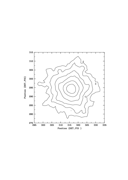
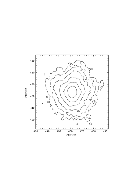
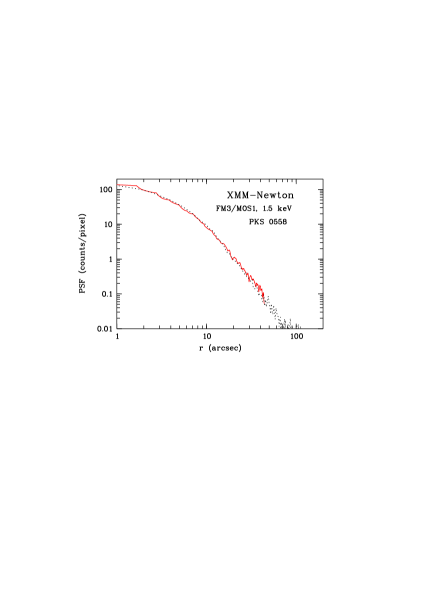
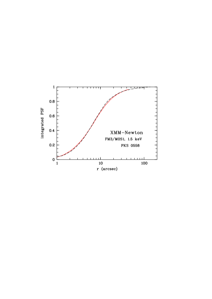
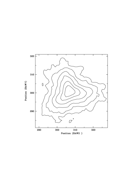
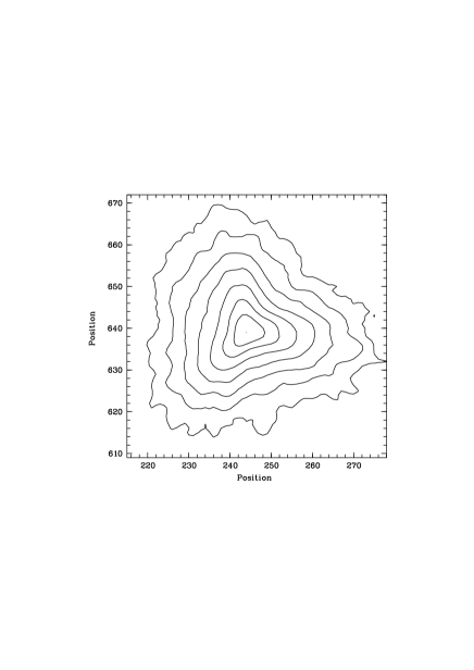
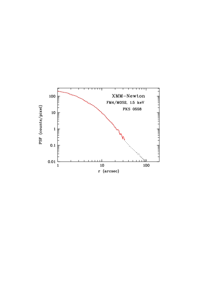
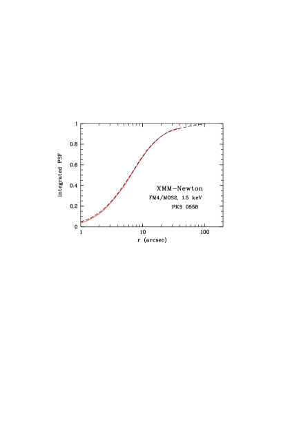
The in-orbit imaging performance of the telescopes is presented in terms of contour lines, describing the surface brightness across the image (Figure 1), the PSF and the encircled energy function (Figure 2) for FM3/MOS1 at 1.5 keV. Figure 3 and Figure 4 show the corresponding data for FM4/MOS2 at 1.5 keV as well. The in-orbit results are compared with the equivalent set of data measured at PANTER. The agreement between on ground and in-orbit measurements is striking. It is noted that the contour line plots have been produced using a smoothing algorithm including the adjacent three pixels in either direction, which tends to increase the width of the core of the PSF. For the determination of the FWHM of the PSF the unsmoothed contours have been used giving the FWHM values listed in Table 2. Figure 5 shows the encircled energy function for FM2/pn at 1.5 keV for the source PSR 0540-69 and the encircled energy function for LMC X-3 for an energy band of (8 ) keV. The corresponding ground calibration measurements are not shown but the results are identical within very small excursions with the in-orbit performance. Because of the comparatively large pixel size of the pn-CCD details of the core of the PSF are not accessible in orbit and the FWHM of the PSF of FM2 cannot be determined. The PSF of FM2 is undersampled by the pn-CCD.
 |
 |
 |
 |
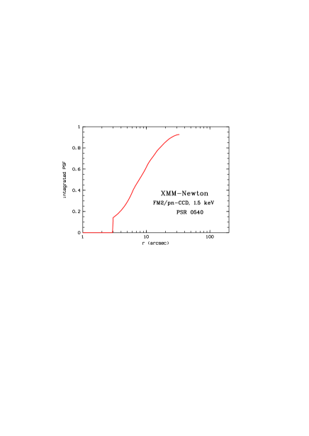 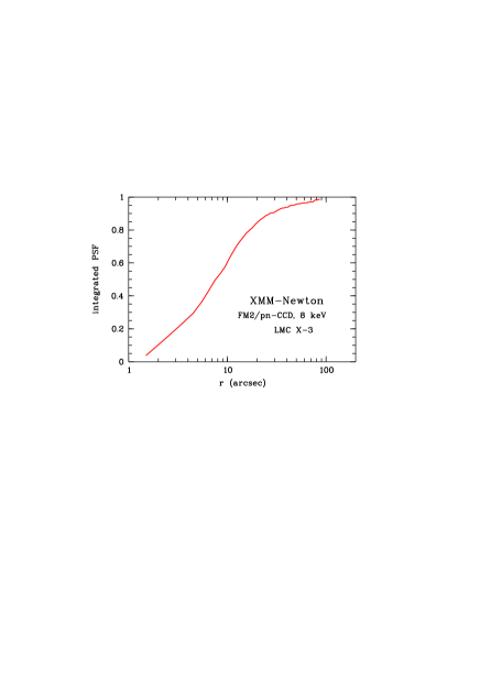 |
Table 2 summarizes the results in terms of characteristic numbers like FHMW and HEW (half energy width of the encircled energy function).
| 1.5 keV | 1.5 keV | 1.5 keV | 1.5 keV | 8 keV | 8 keV | 8 keV | 8 keV | ||
|---|---|---|---|---|---|---|---|---|---|
| orbit | ground | orbit | ground | orbit | ground | orbit | ground | ||
| telescope | FWHM | FWHM | HEW | HEW | FWHM | FWHM | HEW | HEW | |
| (”) | (”) | (”) | (”) | (”) | (”) | (”) | (”) | ||
| FM2/pn | 12.5 | 6.6 | 15.2 | 15.1 | 12.5 | 6.6 | 15.0 | 14.8 | |
| FM3/MOS1 | 4.3 | 6.0 | 13.8 | 13.6 | - | 5.1 | - | 12.5 | |
| FM4/MOS2 | 4.4 | 4.5 | 13.0 | 12.8 | - | 4.2 | - | 12.2 |
5 CONCLUSIONS
Providing that the PSFs of the three X-ray telescopes on board of XMM-Newton have not developed significantly bright wings outside of about 1 arcmin radius from ground to early orbit the following conclusions can be drawn.
-
•
From the contour lines and the FWHM of the PSFs and the agreement with the ground calibration measurements it follows that all three focal plane cameras are in focus.
-
•
The PSFs in orbit are basically identical with those measured on ground; the core of FM2 cannot be resolved in orbit because of the large pn-CCD pixel size.
-
•
The encircled energy functions of FM2, FM3 and FM4 measured in orbit at 1.5 keV agree with those measured on ground, at least out to an angular radius of about 40 arcsec. At 8 keV the FM2 shows the same encircled energy function in orbit as measured on ground.
Beyond this direct comparison further conclusions can be drawn which are related to the mechanical integrity of the telescopes and the X-ray calibration test set-up.
-
•
The X-ray telescopes have not changed their shape during storage on ground or by launch loads.
-
•
The focal plane instrumentation was correctly installed at the required position and no significant movement occurred during launch.
-
•
The mounting and fixture of the mirrors in just one spider support structure at the parabolas’ front is sufficient to maintain the mirrors’ performance.
-
•
Effects of gravity which would potentially distort the mirrors during horizontal X-ray testing in the MPE PANTER test facility are not apparent concluded from the comparison of the ground measurements with the in-orbit results of the PSF.
-
•
The divergence of the X-ray beam in the PANTER test geometry does not limit the assessment of the PSF. Interestingly the non-illumination of the first third of the parabolas’ sections does not change the PSF of the XMM-Newton telescopes. This means that the angular distortions along the meridian lines of the parabola mirrors imposed by the mounting at their front ends are not significantly larger than along the remainder of the meridian lines towards the hyperbolas’ exits.
ACKNOWLEDGMENTS
The provision of the pn-CCD and MOS-CCD in orbit data of XMM-Newton by the EPIC team led by the Principal Investigator Martin Turner of the Leicester University, UK is acknowledged.
REFERENCES
-
1.
”A Cosmic X-ray Spectroscopy Mission”, Proc. of a Workshop held in Lyngby, Denmark on 24-26 June 1985, Proc. ESA SP-239, 1985.
-
2.
B. Aschenbach, O. Citterio, J.M. Ellwood, P. Jensen, P. de Korte, A. Peacock and R. Willingale, ”The High-Throughput X-ray Spectroscopy Mission”, Report of the Telescope Working Group, Proc. ESA SP-1084, 1987.
-
3.
B. Aschenbach and Heinrich Bräuninger, ” Grazing Incidence Telescopes for ESA’s X-ray astronomy mission XMM”, in X-ray Instrumentation in Astronomy II, L. Golub, ed., Proc. SPIE 982, pp. 10-15, 1988.
-
4.
B. Aschenbach, ”Re-Design of the XMM Optics”, Techn. Note XMM/O/MPE, 1987.
-
5.
B. Aschenbach, H. Bräuninger, K.-H. Stephan and Joachim Trümper, ”X-ray test facilities at Max-Planck-Institut Garching”, in Space Optics - Imaging X-ray Optics Workshop, M. Weisskopf, ed., Proc. SPIE 184, pp. 234-238, 1979.
-
6.
D. de Chambure, R. Lainè, K. van Katwijk, A. Valenzuela, G. Grisoni et al., ”Lessons learnt from the development of the XMM optics”, Intern. Symposium on the Optical Design and Production, Berlin 1999, EUROPTO Series 1999, in press.
-
7.
B. Aschenbach, ”Design of an X-Ray Baffle-System”, Techn. Note XMM-TS-FMP004, 1996.
-
8.
D. de Chambure, R. Lainè, K. van Katwijk, W. Rühe, D. Schink et al., ”The X-ray Baffle of the XMM telescope: Development and Results”, Intern. Symposium on the Optical Design and Production, Berlin 1999, EUROPTO Series 1999, paper no. 3737-53, in press.
-
9.
E. Pfeffermann, U.G. Briel, H. Hippmann, G. Kettenring, G. Metzner et al., ”The focal plane instrumentation of the ROSAT telescope”, Proc. SPIE 733, pp. 519-532, 1986.
-
10.
R. Egger, B. Aschenbach, H. Bräuninger, W. Burkert, T. Döhring and A. Oppitz, ”X-ray calibration of the mirror module FM2 at PANTER test facility - test results”, Techn. Note XMM-TS-PA063/970829, 1997.
-
11.
R. Egger, B. Aschenbach, H. Bräuninger, W. Burkert, T. Döhring and A. Oppitz, ”X-ray calibration of the mirror module FM3 at PANTER test facility - test results”, Techn. Note XMM-TS-PA070/980115, 1998.
-
12.
R. Egger, B. Aschenbach, H. Bräuninger, W. Burkert, K. Molthagen and A. Oppitz, ”X-ray calibration of the mirror module FM4 at PANTER test facility - test results”, Techn. Note XMM-TS-PA077/980723, 1998.
-
13.
U.G. Briel, B. Aschenbach, M. Balasini, H. Bräuninger, W. Burkert, K. Dennerl et al., ”The in-orbit Performance of the EPIC-PN CCD-Camera on Bord of XMM-Newton”, in X-ray Optics, Instruments and Missions, J. Trümper and B. Aschenbach, eds., Proc. SPIE this volume, 2000.
-
14.
L. Strüder, N. Meidinger, E. Pfefferman, R. Hartmann, H. Bräuninger et al., ”X-ray pn-CCDs on the XMM-Newton Observatory”, in X-ray Optics, Instruments and Missions, J. Trümper and B. Aschenbach, eds., Proc. SPIE this volume, 2000.
-
15.
J.W. den Herder, A.J. den Boggende, G. Branduardi-Raymont, A.C. Brinkman, J. Cottam et al., ”Description and performance of the reflection grating spectrometer on board of XMM-Newton”, in X-ray Optics, Instruments and Missions, J. Trümper and B. Aschenbach, eds., Proc. SPIE this volume, 2000.